Abstract
To improve the life of the meshing pair in single screw compressor (SSC), several meshing pair profiles (MPP) were proposed for raising the lubrication properties. Therefore, it is necessary to evaluate the lubrication performance of the MPPs. In this paper, an evaluation method based on micro deflecting motion trajectory (MDMT) is proposed and the theoretical model to realize MDMT is established. The model mainly contains a geometric model, a thermodynamics model, a hydrodynamic lubrication model and corresponding algorithm. With the presented method, three kinds of MPP including single straight line type (SSLT), single column type (SCT) and multi column type (MCT) have been analyzed. Obtained results show that compared to the SSLT and SCT, the MCT generates the greatest peak value of the water film pressure. The total torque applied on the gate-rotor generated by the water films decreases with the increment of the discharge pressure and increases with the machine size. The water film stiffness firstly decreases and then increases with the micro deflecting angle increasing. The water film stiffness at trailing side is always larger than that at leading side. As the discharge pressure increases, the MDMT curves approach the leading flank, and the lubrication properties get worse. With the machine size increasing, the MDMT curves move towards the trailing side and the lubrication performance is improved. Comparing to the other two MPPs, the MCT can achieve floating mesh without contact in relatively larger machines and comparably lower discharge pressure.
1. Introduction
Single screw compressors (SSCs) are widely applied in air compression, refrigeration, petroleum and petrochemical industries due to advantages such as high efficiency, excellent mechanical balance and compact structure. A SSC is mainly constituted of a screw, a pair of gate-rotors and a casing, as shown in Figure 1. A screw and a gate-rotor are named a meshing pair. The gas is compressed in the working chamber formed by the screw groove, gate-rotor tooth and the inner wall of the casing. The working principle is shown in Figure 2. The inlet gas (blue) fills the working chamber as the tooth closes the screw groove. With further rotation, the working chamber shrinks and the gas is compressed (pink). As the working chamber connects the discharge orifice on the casing, the compressed gas (red) is discharged. Liquid is injected into working chambers of SSCs to cool the gas, lubricate the meshing pair and seal the gaps.
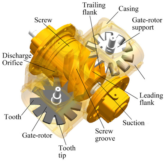
Figure 1.
Typical structure of a single screw compressor (SSC).
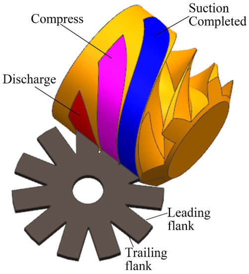
Figure 2.
Working principle of the SSC.
A main drawback of the SSC is the deterioration of its discharge capacity. A lot of SSCs sold in the market showed a sharp decrease of discharge capacity for more than 10% after one or two years of initial running, due to the abrasion of the gate-rotor and the enlargement of the meshing pair clearance even under liquid injection [1]. A lot of worn gate-rotors were collected [2] and one of them is shown in Figure 3.
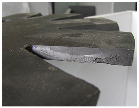
Figure 3.
A worn gate-rotor.
A volume of research has been conducted on improving working life of the SSCs. Structure improvement such as floating gate-rotor was proposed to increase the flexibility of the gate-rotor and reduce wear [3]. The introduction of the wear-resistant material PEEK to the gate-rotor and the improvement of the machining precision raised the stability of SSCs to some extent [2]. However, these efforts have been proved to have limited contribution. Several researchers have suggested that meshing pair profile (MPP) is the key factor of the abrasion problems [4]. Zimmern proposed the original MPPs including single straight line type (SSLT) and single column type (SCT) [5]. The SSLT is shown in Figure 4a; the meshing surface is only a straight line. Therefore, the meshing area approaches zero and the meshing surface curvature along the rotating axis of the gate-rotor is infinite, which cause quick abrasion according to the tribology principle [6]. As shown in Figure 4b, the meshing line of SCT is not fixed and can slide onto the triangular column surface. Feng developed a multi straight lines type (MSLT) MPP, which makes the meshing line switch between all the straight lines [7], as shown in Figure 4c. Generally speaking, the increase of the straight line number will bring better dry friction resistance performance. Combining the advantage of the SCT and the MSLT, a multi-column type (MCT) MPP was proposed [8], as shown in Figure 4d. The contact area is maximized and the curvature is minimized. This study proposed the concept of the MCT and its basic design method, without further properties investigations. Li designed a test rig with eccentric wheel to study the wear resistance property of different MPPs [9]. The range of the enveloping angle, contact stress and relative velocity were accorded with the real condition of SSCs. After 20 h running, the wear loss of sample teeth with different profiles was tested by three coordinate measuring machines. The measurement results show that MCT profile has the best wear resistance and the SSLT profile has the worst performance. Wang proposed a theoretical method to predict the wear characteristics of the MPPs by calculating friction angle and Hertz contact stress [10].
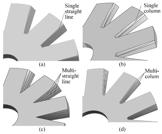
Figure 4.
Four kinds of meshing pair profiles (MPPs): (a) single straight line type (SSLT) (b) single column type (SCT) (c) multi straight lines type (MSLT) (d) multi column type (MCT).
Along with the development of MPPs, much research has been devoted to the lubrication characteristics. The lubrication characteristics are even more important than the wear resistance since the gate-rotor tooth will never contact with the screw thread flank if the lubrication is well formed between the meshing pair. Reference [11] discussed the possibility of hydrodynamic lubrication in the clearance between the screw groove flank and the gate-rotor tooth flank, pointing out that the necessary conditions for hydrodynamic film including wedges, sufficient sliding velocity and liquid flow from big inlet to small outlet are available. Heidrich suggested that for the water flooded SSCs, the tribology property may get worse because of low viscosity of water and an acceptable working life may not available [12]. Jin calculated the oil film thickness under a certain load by Martin equation and verified the existence of the oil film between the meshing pair by an experiment utilizing the electrical insulation of the oil [13]. Post and Zwaans researched the hydrodynamic properties in SSCs, calculating the oil film pressure distribution by finite difference method and comparing the hydrodynamic lubricating characteristics of SSLT and SCT [14,15]. Sun investigated the oil film force at both sides of the tooth and indicated that the oil film force on leading flank is always smaller than on trailing flank [16]. This numerical result accords with the actual phenomenon that the gate-rotor was always worn seriously on the leading flank [17]. Wu studied the Couette-Poiseuille flow in two-dimensional asymmetric gaps and gave the approximate solution of the pressure distribution, which could serve as a reference for investigating the pressure distribution in meshing pair gaps [18]. Huang optimized the SCT MPP and developed an oil flooded prototype [19]; nevertheless, this study only concentrated on one MPP and no comparison study was conducted. Li designed a modeling experiment to simulate the motion of the meshing pair with water lubrication and verified that water in the gap can establish hydrodynamic lubrication and tested the water film force [2], but this experiment ignored the Poiseuille effect and the characteristic of synchronous meshing of the three teeth was not taken into consideration. Further, the hydrodynamic lubrication properties of the SSLT and MCT profiles in water flooded SSCs were compared. The numerical results show that the MCT profile generates greater water film pressure and thrust than SSLT profile [20]. However, this work did not propose a comprehensive and intuitive method to evaluate the lubrication properties of the MPPs. In addition, the influences of the working condition and the machine size were not investigated.
The wear resistance performance of the MPP under dry friction, boundary or mixed lubrication can be judged by testing the wear loss of gate-rotors or calculating the Hertz contact stress. However, how does one evaluate the fluid film lubrication properties of the MPPs? For one gap between the friction pair such as a journal bearing, the lubrication properties can be well described by the liquid film pressure, thrust or thickness. Nevertheless, there are two gaps at leading and trailing sides of the tooth (See Figure 5). The liquid film pressure, thrust or thickness of one gap cannot represent the tooth lubrication properties. Actually, there are always three teeth of the gate-rotor meshing with the screw at the same time (See Figure 2) and six gaps are generated. Therefore, it is more complex for evaluating the MPPs’ lubrication properties.
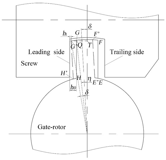
Figure 5.
The schematic drawing of the micro deflecting motion.
It can be inferred that the gate-rotor will rotate slightly in the screw grooves if the liquid in the six gaps applies a resultant torque on the gate-rotor and the gate-rotor will deflect on the axis of the gate-rotor. Taking one of the teeth to study, it deflects about the gate-rotor axis slightly from EFGH to E’F’G’H’ (See Figure 5). Consequently, a geometric parameter named micro deflecting angle δ is proposed to describe the micro deflecting motion. By calculating the micro deflecting angle δ of every moment in a period, the micro deflecting motion trajectory (MDMT) of the gate-rotor is available. The MDMT of the gate-rotor is similar to the journal bearing center track to some extent. For problems such as deflection trajectory or center track, some scholars have conducted relative research. Jiang and Pi established a model of the tool tip ellipse trajectory deflection control, measured it and analyzed the relation between tool tip ellipse trajectory deflection and the cutting quality [21]. Xie defined a new concept of instantaneous whirling speed of axis orbit and studied its new perspective for the vibration analysis of cracked rotors [22]. To bore elliptical hole, Liang and Lu applied Gauss pseudospectral method to obtain the relation between load capacity and servo system, then made the shaft center orbit quickly get close to the designed elliptical hole [23]. To improve the stability of the journal bearing in twin-screw compressors, Wang presented a homogeneous two-phase flow model to calculate bearing axis orbit and analyzed the impact from evaporating temperature and different built-in volume ratio [24]. By analyzing the MDMT, the working state of the gate-rotor and the tribology information can be obtained. The lubrication characteristics of the MPPs in SSCs can be evaluated by the MDMT comprehensively.
In this paper, a mathematical model of the MDMT is established. Based on the model, numerical calculations have been carried out to evaluate the lubrication performance of different MPPs in machines with different sizes or under different working conditions.
2. Mathematical Modeling
2.1. Geometric Model
2.1.1. Basic Geometric Parameters
The main geometric parameters are shown in Figure 6. As the gap width of leading side equals to that of the trailing side (the gate-rotor is drawn by solid line), δ is set zero. If the gate-rotor deflects anticlockwise in the screw groove (indicated by dashed line), δ is set positive. On the contrary, δ is set negative.
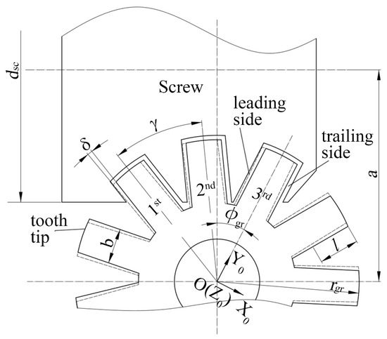
Figure 6.
The basic geometric parameters of the meshing pair.
2.1.2. MPP
For a SSC, the MPP refers to the shape of the tooth flank and the screw groove flank meshing with it. Coordinate system X0Y0Z0 is fixed on the gate-rotor (See Figure 6). Taking the leading flank as an example, the tooth flank profile can always be expressed as a function in coordinate system X0Y0Z0:
where x is the coordinate value of the tooth flank profile in OX0 direction; the subscript “a” refers to the leading flank; l is the tooth length parameter. The MPPs of SSLT, SCT and MCT are deduced in the previous references [16,19,20].
2.1.3. The Meshing Pair Gap Shape Function
During the meshing process, the variation range of the screw thread elevation angle α equals to that of the tooth flank elevation angle β (See Figure 7). Meanwhile, the screw thread length is far longer than the tooth thickness. Therefore, the curvature of the screw thread flank is far smaller than that of the tooth flank and the screw thread flank can be considered as a straight line in the range of tooth thickness th, as shown in Figure 7.
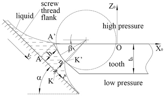
Figure 7.
The cross section of the meshing pair.
Since the screw thread elevation angle α varies along both the radial and the axial direction of the screw, the screw thread of leading flank can be expressed as:
where
where the subscript “K” refers to the contact point K on the screw thread.
The gap between the screw thread flank and the tooth flank can be described by a gap thickness funtion h and is given by:
It is noteworthy that the gap shape not only varies along with the gate-rotor rotating angle φgr but also varies along with the tooth length parameter l. Therefore, the gap is changing and twisted. Compared to the clearance of journal bearing, the gap between the meshing pair is much more complicated.
2.2. Thermodynamics Model of the SSCs
Since the fluid flow in the meshing pair gap is partly driven by the differential pressure between the working chamber and the casing cavity, it is necessary to calculate the thermodynamic process of the compressor. The pressure of the casing cavity approximates to the atmospheric pressure. In order to calculate the working chamber pressure and temperature, a thermodynamics model is adopted to simulating the working process of the SSC.
According to the thermodynamics principle of the variable mass system, the basic equations for simulating the working process of air compressors are given as follows [25]:
where P is the gas pressure in the working chamber; k is the specific heat ratio; Rg is the gas constant; Vc is the gas volume in the compression chamber; mi is the leakage mass of the gas flow into the chamber; Q is the heat transfer capacity between the gas and the liquid; v is the specific volume of the gas; Ti is the temperature of the gas leaking into the working chamber; T is the temperature of the gas in the working chamber and can be calculated by:
Several unknown relations are included in the basic equations, such as heat transfer and leakage items. The calculation methods for these items and the whole basic equations are given in references [26,27,28,29,30,31,32]. The basic equations and the items of heat transfer and leakage constitute the thermodynamics model.
The compression process described by Equations (5) and (6) is neither an adiabatic process nor an isothermal process but a polytropic process. Although a lot of water is injected, the isothermal compression process cannot be achieved because of the high rotation speed and short time for heat transfer. The polytropic process index is much closer to the adiabatic process [25].
2.3. Lubrication Model
2.3.1. The Favorable Conditions to Form Hydrodynamic Lubrication
1) Wedge
There is a wedge in the meshing pair, which is surrounded by the dashed lines in the clearance (the quadrilateral AKK’A’), as shown in Figure 7. Since the wedge is a part of the gap, its included angle varies along with φgr and l. Moreover, due to the meshing point sliding on the tooth flank during the meshing process, the wedge length changes except SSLT.
2) Relative velocity between the two meshing surfaces
The liquid is not only a Poiseuille flow but also a Couette flow because the relative move of the meshing pair. The relative velocity vr between gate-rotor and screw is given by:
where vgr is the velocity of the of the gate-rotor tooth at the meshing point ‘K’; vsc is the velocity of the of the screw at the meshing point K. ωgr and ωsc are the angular velocity of the gate-rotor and the screw, respectively; rgr,K and rsc,K are the radii from the meshing point K to the gate-rotor axis and screw axis, respectively.
3) Flow direction
The liquid flows from the high pressure side to the low pressure side. The bigger opening of the wedge is exactly located at the high pressure side. Therefore, the inlet is bigger than the outlet of the wedge.
4) The wedge is filled with liquid
In general, the liquid injection quantity is very huge in SSCs. For example, the injection flow in a SSC with discharge capacity of 6 m3·min−1 is about 60 L·min−1. Under the effect of differential pressure and relative velocity, a large amount of liquid is brought to the inlet of the wedge. Since the wedge width is only dozens of micrometers, the liquid accumulated at the inlet can hardly be drained out through the clearance. The gas is almost impossible to cross the clearance.
Furthermore, references [33,34,35] study the leakage characteristics of SSCs. During calculation of the leakage properties of the gap between the tooth flank and screw thread flank, the flow in the clearance is supposed to be single phase of liquid. The simulating volume efficiencies are consistent with the experimental data. Therefore, the deduction that the wedge is filled with liquid is reasonable.
5) The hydrophilicity of the material
For the water lubricated friction pair, the hydrophilicity of the material is beneficial for the formation of the hydrodynamic water film [36]. In most water flooded SSCs sold in the market, screws are made of tin bronze and gate-rotors are made of PEEK. A metallic oxide film which is polar always emerged on the surface of copper alloy [37]. Therefore, the screw surface can be viewed as hydrophilic. The PEEK material has a wetting angle range of 20–83°, which is smaller than 90°. Therefore, it should be classified to hydrophilic material [38].
In this paper, an observational experimental has been conducted to verify whether the materials are hydrophilic. Several drops of deionized water with different size were dropped to the surfaces of the screw and the gate-rotor, as shown in Figure 8. It can be seen that the wetting angle of the droplet on the bronze surface is slightly larger than that on the PEEK surface. However, the maximum wetting angle on the screw is still smaller than 60°, which proves that the meshing pair surfaces have better hydrophilicity and are helpful to establish hydrodynamic lubrication.
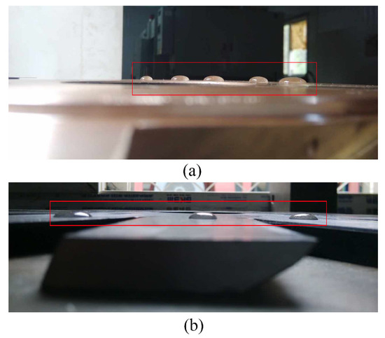
Figure 8.
The hydrophilicity of the materials: (a) the screw surface (b) the gate-rotor surface.
2.3.2. Pressure Distribution in the Liquid Film
To calculate the pressure distribution, a coordinate system Knτz is established (See Figure 7). K is the meshing point on the screw groove flank. Axis n is vertical to the screw groove flank. Axis τ is along the screw groove flank. Axis z is along the tooth length direction. Knτz is a moving system since the coordinate origin K and the directions of axes n, τ, z vary along the meshing process. The velocity U of the liquid flowing through the gap is composed of 3 components u, v, w. Velocities u, v, w are along the directions of n, τ, z respectively.
Usually, the Reynolds equation is used to solve the hydrodynamic lubrication problems. The inertia term is ignored during the derivation process of this equation. However, the inertia term cannot be always neglected, even in laminar flow [39]. Especially for the water flooded SSC, the inertia term must be considered since the water viscosity is very small. Therefore, the Reynolds equation is not applicable for this problem. The liquid film pressure model is deduced based on the N-S equations for Newtonian fluid:
where ρ is the liquid density; t is the time; p is the liquid film pressure; μ is the dynamic viscosity; λ is the second viscosity coefficient; S is the stress tensor; f is the body force. To obtain the governing equation, several assumptions are made and Equation (8) is simplified accordingly [20]:
1) The flow is viewed steady state under a certain gate-rotor rotating angle φgr. Hence, the item ∂/∂t is neglected. Since water is incompressible, divergence of velocity equals 0. Because liquid injection amount is very large and the heat transfer time is very short, the temperature rise of liquid is small (in a 6 m3·min−1 prototype, the tested temperature rise often does not exceed 10K) and coefficients λ and μ are viewed as constants. Body force f, such as gravity, is ignored. Then, Equation (8) is simplified to the following equation:
2) Since water film thickness is usually only dozens of microns, the velocity component u along the liquid film thickness direction n is ignored and the gradient ∂2/∂z2 and ∂2/∂τ2 along the other two directions are neglected. Further, the differential equation is integrated in liquid film thickness direction and Equation (9) is deduced to:
The integral continuous equation is given by:
Equations (10) and (11) are the governing equations of the liquid flow in the meshing pair clearance. However, solving the governing equations is still very difficult because of the inclusion of the nonlinear inertia item and the complex gap shape h. To simplify this problem, the tooth flank is divided to many infinitesimals. The infinitesimal width is dl, as shown in Figure 9. In infinitesimal dl, ∂p/∂z is far smaller than ∂p/∂τ. Therefore, the tooth flank and the screw groove flank in the width dl can be viewed as an infinite-width thrust bearing. Accordingly, the whole flank is composed of many infinite-width thrust bearings in a row.
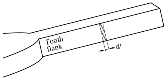
Figure 9.
The infinitesimal of the tooth flank.
By introducing the mass mean velocity vm, Launder and Leschziner linearized the inertial item of the equations which is similar to the governing equations and deduced the pressure distribution [39]:
where
The boundary conditions are given as follows:
The analytic solution of the water film pressure distribution can be deduced by integrating Equation (12):
where
where
In conclusion, in the infinitesimal dl, the water film pressure distributes in one dimension along τ direction. Since the sliding velocity and the clearance shape in every infinitesimal are different, it is necessary to calculate pressure distribution in each infinitesimal to obtain the quasi-two-dimensional pressure information of the whole tooth flank.
2.3.3. The Micro Deflecting Motion Driven by the Liquid Film Force
Supposing δ = 0 at initial time, liquid film force at leading side of the ith tooth generates a torque Ta,i which rotates the gate-rotor clockwise. At trailing side, the liquid film torque Tb,i rotates the gate-rotor anticlockwise. The liquid film torque applied on one tooth flank can be calculated by:
where lm is the length of the tooth flank meshing in the screw; tt is the tooth thickness; b is the tooth width; lt is the whole tooth length; l is the tooth length parameter.
Supposing only the ith tooth meshes with the screw, the gate-rotor will deflect anticlockwise under the condition that Ta,i is smaller than Tb,i. Further, the gap at leading side decreases and Ta,i increases. Meanwhile, the gap at trailing side increases and Tb,i decreases until Ta,i and Tb,i get balanced.
However, if the increased Ta,i still cannot balance the decreased Tb,i, the gap at leading side will decrease until the first pair of micro convex bodies contact at tooth tip. The state turns to mixed lubrication and the contacting force Fn starts to act. In case Tb,i cannot even be balanced by Ta,i and the torque generated by Fn, the gap at leading side will further decrease and the liquid film thickness reduces to several molecular layer. The state comes to boundary lubrication and Ta,i is finally balanced by the contact force.
Both in mixed and boundary lubrication conditions, abrasion occurs on the working surfaces. However, this paper does not discuss on wear characteristics under mixed or boundary states but focuses on the ability to keep full fluid film lubrication of the MPP. Therefore, when the full fluid film lubrication state turns to mixed lubrication, the fluid film is viewed to be broken and the clearance of the tooth tip ht at this moment is defined as the minimum allowable clearance hmin.
To determine the hmin value, the dividing criteria of lubrication state should be introduced first. The lubrication state can be defined by film thickness ratio λ. When the mating surfaces are under boundary lubrication condition with preponderant contact on the roughness of contacting surfaces, λ < 1; when the mating surfaces are under mixed lubrication, 1 ≤ λ < 3; when the mating surfaces are under fluid film lubrication, λ ≥ 3 [40]. Therefore, to ensure full fluid film lubrication, the λ value shoud be 3 and hmin which is given by [40,41]:
where σ is the composite surface roughness and is expressed as:
where Rq1 and Rq2 are the root mean square deviation of roughness of the tooth flank and the screw groove flank respectively. The σ value under different Rq1 and Rq2 are calculated and listed in Table 1.

Table 1.
The composite surface roughness σ.
Different processing method will lead to different Rq1, Rq2 and σ. In our lab, the tooth flank is ground by a grinding wheel and Rq1 can reach 1.6 μm, the screw groove flank is milled by a milling cutter and Rq2 can reach 3.2 μm. Therefore, σ = 3.578 μm and hmin equals to 10.7 μm.
The clearance of the tooth tip ht change with the variation of the deflecting angle δ. Their relationship is deduced as follows (see Figure 5 and Figure 6):
where h0 is the gap width as δ = 0 (See Figure 5); η is the half angle of the tooth width (See Figure 5).
δlim is the maximum allowed micro deflecting angle. As the tooth tip ht clearance at leading side or trailing side reaches hmin, δ equals +δlim or −δlim respectively. δlim can be deduced by Equation (21):
2.3.4. The Lubrication Properties with Multi Teeth Coupled
Equation (18) and the following two paragraphs mainly describe the micro deflecting motion of the gate-rotor driven by one tooth, however, there are often three teeth meshing with the screw at the same time, as shown in Figure 6. For the first tooth, the meshing length at trailing side is longer than that at leading side. It may make the gate-rotor to rotate in a clockwise direction. To the third tooth, the opposite is the case. The meshing length at each flank of the second tooth is relatively close. Therefore, the direction of the micro deflecting motion needs to be determined by the total circumferential torque Tt.
Total torque Tt is the algebraic sum of the liquid film torques of the six gaps and the friction torque TF caused by bearings and seals. Tt can be decomposed into resultant water film torque of leading side Ta, resultant water film torque of trailing side Tb and the friction torque TF. Ta and TF are set positive since they drive the gate-rotor to rotate clockwise and Tb is set negative.
Supposing the rolling bearings and mechanical seals are employed in the gate-rotor shaft, friction torque TF can be expressed by:
where TFR,j is the friction torque of the jth rolling bearing and is given by [42]:
where μR is the friction factor of the rolling bearing; Fa and Fr are the axial and radial load of the bearings respectively and are deduced in the reference [43] and TFM,k is the friction torque of the kth mechanical seal and is given by [42]:
where f is friction factor of the seal end faces; dm is the average diameter of the seal end face; b is the width of the seal end face; pc is the specific pressure of the seal end face; vs. is the average speed of the seal end face.
2.3.5. The Algorithm of Micro Deflecting Motion Trajectory
Ta+ Tf and Tb are each other’s load. The mechanism of the micro deflecting motion of the gate-rotor with multi teeth coupled is similar to that of the single tooth elaborated in Equation (18) and the following two paragraphs.
δbal is balanced micro deflecting angle when Tt is 0. As the δbal under every φgr is worked out, the micro deflecting motion trajectory is achieved. If Tt cannot get balanced even |δ| equals or exceeds |δlim| under a certain φgr, the iteration will be terminated and jumped to the next step of φgr+Δφgr. δlim or −δlim is assigned to δbal under this certain φgr to represent wear occurrence.
The calculation flowchart of the micro deflecting motion trajectory is shown in Figure 10.
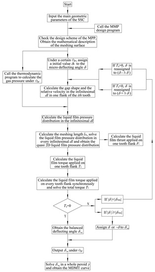
Figure 10.
The calculation flowchart of the micro deflecting motion trajectory.
3. Results and Discussion
In this section, the lubrication performance of different MPPs in machines with different sizes or under different working conditions is presented. Since the MSLT is a transitional MPP and has not been developed for industrial applications, the SSLT, SCT and MCT are set as the study objects. Machines of three discharge capacities are designed and listed in Table 2.
Table 2.
Parameters of the prototype.
3.1. Pressure Distribution of Different MPPs
In the 6 m3·min−1 SSC, the water film pressure distributions at leading flank under rated discharge pressure were calculated under δ = 0° and φgr = 14.9°. Under this gate-rotor rotating angle, the property that the instantaneous meshing line cross different columns of MCT can be well demonstrated and the pressure of the compression chamber is 325300Pa. As shown in Figure 11, the calculating data are plotted to a 3D surface for every MPP. The 3D surface is projected to the Y0OZ0 plane and a 2D pressure distribution of the tooth flank is available.
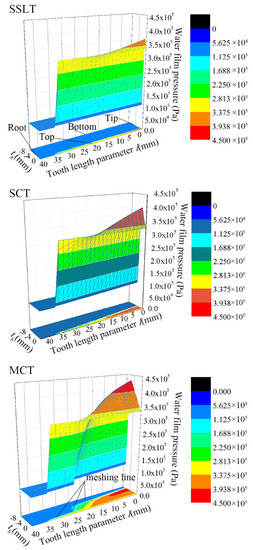
Figure 11.
The pressure distribution of the water film.
For SSLT, the peak value of the water film pressure is 332300Pa and emerges at tooth tip. Although the relative velocity gets its minimum at tooth tip, the included angle of the wedge reaches its maximum at the same location. Along with the increases of l, the hydrodynamic effect declines gradually until it vanishes at l = 22.3mm. As l > 36.1 mm, the tooth is out of the screw and there is no liquid film. Since the meshing line is constant, the water film in the 2D plane is a thin and long rectangle. Due to its weak hydrodynamic effect and small action area, the thrust force to the leading flank is small.
For SCT, the peak value is 362000Pa and also emerges at tooth tip. The acting area of the water film presents a triangle in the 2D plane since the meshing point varies from bottom to top of the tooth in the tooth thickness direction (th) along with the increment of l. Compared to the SSLT, the hydrodynamic effect is much stronger and the acting area is bigger.
For MCT, the peak value is 431102Pa and still emerges at tooth tip. As l < 25.8mm, the meshing line is on the column near bottom of the tooth and the action area is very wide. As l > 25.8mm, the meshing line is on the column near top of the tooth and the action area is narrow. Under this φgr, the MCT has the strongest hydrodynamic effect and the biggest action area among the 3 MPPs.
It can be found that the hydrodynamic effect declines from tooth tip to tooth root for all types of MPP. It is mainly because both the contraction ratio of the wedge and the relative velocity decrease continuously with the increment of l.
3.2. Lubrication Performance under Different Discharge Pressure
The lubrication performance for different MPPs adopted in the 6 m3·min−1 SSC under discharge pressure of 0.8 MPa, 1.2 MPa and 1.6 MPa (absolute pressure) is investigated in this section.
3.2.1. Total Torque Tt in a Whole Period
The included angle between two adjacent teeth is γ. Calculating the lubrication properties, the calculation period is not 2π but γ, since the gate-rotor coincides to itself after a rotation angle of γ. In this calculation, δ is set 0 throughout. The calculation result is shown in Figure 12.
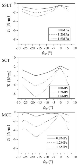
Figure 12.
The total torque of a whole period under different discharge pressures.
Total torque Tt is negative in the whole period, which shows that water films at trailing sides are more powerful than those at leading sides without deflecting (δ = 0). That Tt is negative also implies that the water film at leading side will bear the load of |Tt|. The smaller value of Tt means |Tt| is bigger and more difficult to bear by the leading side films.
It is easily found that Tt decreases with the discharge pressure raising for any definite MPP. This proves that Tb grows faster than Ta and the load |Tt| for the leading side films raises with the discharge pressure increment. Taking MCT as an example, the peak of |Tt| increases by 494.52% from 0.8MPa to 1.6 MPa.
It can also be found that under any discharge pressure, the SCT has the minimum Tt. The SSLT has the maximum of Tt under 1.6 MPa and 1.2MPa and the MCT has the maximum of Tt under 0.8MPa. Under the discharge pressure of 1.6MPa, Tt of SSLT varies from −2.905 N·m to −0.477 N·m, Tt of SCT varies from −8.526 N·m to −2.258 N·m, Tt of MCT varies from −5.506 N·m to −0.531 N·m. The SSLT has the minimum load |Tt| and the SCT has the maximum load |Tt|. However, SSLT cannot be regarded as the best profile since it is still related to the water film stiffness.
In addition, all the Tt curves in Figure 12 are negative. This can be explained by the fact that although there are three teeth meshing with the screw, the contributions of different tooth to Tt is not the same. The first tooth (See Figure 6) is the dominant one due to the high gas pressure applied on it. In the first tooth, the meshing line at trailing side is longer than that at leading side. Therefore, the water film torque generated at trailing side of the first tooth is the maximum one as δ = 0. This is also the basic reason why all the Tt curves are negative.
3.2.2. Water Film Stiffness
Total torque Tt is calculated in the range of −δlim to δlim under the gate-rotor rotating angle φgr0 when one of the teeth just closes the screw groove. The numerical results are shown in Figure 13.
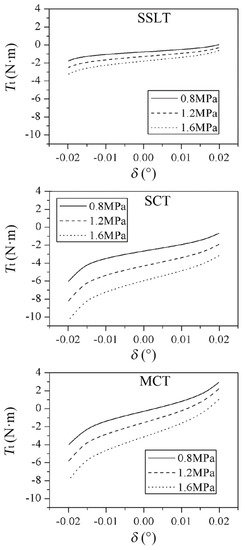
Figure 13.
The total torque at various deflecting angles under different discharge pressures.
Tt increases with the increase of δ, because the water films at leading side get thinner and generate bigger torque Ta while the films at trailing side become thicker and generate less |Tb|. As δ approaches δlim = 0.02°, Tt rises rapidly to prevent contact at leading side. When δ approaches −δlim = −0.02°, Tt falls rapidly to prevent contact at trailing side. If Tt > 0 under δlim and Tt < 0 under under −δlim, the gate-rotor is viewed to have self-regulating capability.
It can be seen that the variation ranges of Tt under the discharge pressure 0.8MPa are −1.773~0.028N·m, −6.03~−0.681N·m and −3.997~3.136N·m for SSLT, SCT and MCT, respectively. Only SCT cannot get a positive value even when δ equals δlim, which means wear occurs in the SCT meshing pair.
When the discharge pressure increases to 1.2MPa and 1.6MPa, all the Tt curves drop and only the MCT keeps the Tt positive under δlim, which represents that the MCT may have the best self-regulating ability under φgr0.
By derivation the Tt curves in Figure 13, the curves of the water film stiffness S are obtained as shown in Figure 14. The stiffness of the water film in the meshing pair can be understood as follows: the water film in the infinitesimal dl can be seen as a micro spring, the micro springs at different tooth length l in a tooth flank constitute a spring combination. All the spring combinations at different tooth flanks form a spring system. The water film stiffness can be regarded as the stiffness of the spring system.
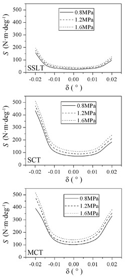
Figure 14.
The water film stiffness under different discharge pressure.
It can be observed that the water film stiffness firstly decreases and then increases as δ increases (See Figure 14). In the range of -0.01–0.01°, the water film stiffness almost remains a constant (Figure 13). The water film stiffness S at δ = −δlim (trailing side) is often larger than that at δ = +δlim (leading side).
The water film stiffness rises when discharge pressure increases. Taking MCT as an example, the S values under δ = −δlim are 391.01 N·m·deg−1, 477.57 N·m·deg−1 and 515.09 N·m·deg−1 under 0.8 MPa, 1.2 MPa and 1.6 MPa.
Since contact often occurs at leading side, the water film stiffness at +δlim is very important, which represents ability of resistance to wear. It is found that the MCT has much higher water film stiffness at +δlim when compared to the SSLT or SCT. Under discharge pressure of 0.8 MPa, the S values under δ = +δlim are 157.69 N·m·deg−1, 391.00 N·m·deg−1 and 433 N·m·deg−1 for SSLT, SCT and MCT, respectively.
The results shown in Figure 13 and Figure 14 are only under a certain gate-rotor rotating angle φgr0; nevertheless, the evaluation of the MPP needs to be proceed in a whole period. In addition, calculations for loads and water film stiffness are indirect for hydrodynamic properties evaluation. Therefore, the MDMT evaluation method is proposed for this purpose.
The gate-rotor tooth or the three teeth together can be viewed as a combined double slider. It can bear load in both directions and can even be unloaded. The gaps value is coupled with the load generated by water films and they are influenced by each other.
3.2.3. MDMT Calculation Results
The calculation results of MDMT under different discharge pressure are shown in Figure 15. Since δbal in this calculation is always greater than 0, the coordinate value on y axis is set from 0 to +δlim. If Tt remains negative under the condition that δ = +δlim; it indicates that wear occurs at leading side and the contact force will be involved to balance the negative Tt. In this case, the δbal is set +δlim.
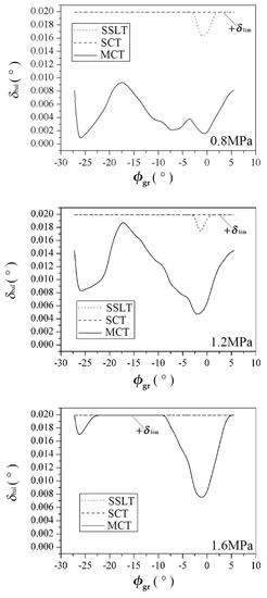
Figure 15.
The micro deflecting movement trajectory (MDMT) curves under different discharge pressure.
Under the discharge pressure of 0.8 MPa, the MDMT curve of SCT always coincides with the straight line of δbal = +δlim in a whole period γ. This result suggests that the water films at leading side cannot afford sufficient bearing capacity to bear the torque generated by water films of trailing side even when δ = +δlim and contact force from the leading side participates in balancing the negative Tt. The MDMT curve of SSLT coincides with the straight line of δbal = +δlim in a whole period except a small region which φgr ranges from −2.49° to 1.51°. In this small region, the hydrodynamic lubrication is established for the leading side and Tt=0 or δbal is available. However, in this region, δbal is too small; in other words, the water films at leading side are too thin when the gate-rotor gets balanced. Contact is still prone to occur under shock. The MDMT curve of MCT is always kept in the region of 0~+δlim, which represents the MCT has good self-regulating ability and contact will not happen in both sides in a whole period γ. It suggests that the gate-rotor is floating in the water films of both sides and meshing with the screw. In addition, the MDMT curve of MCT is relatively far away from the line of δbal = +δlim, which proves that water films at leading side still have enough thickness to remain at full fluid hydrodynamic lubrication and to resist some impact.
Under the discharge pressure of 1.2MPa, only in a very small region about 3.4° (−2.55°~0.82°) the MDMT curve of SSLT does not coincide with the straight line of δbal = +δlim. The MDMT curve of SCT is still the straight line of δbal = +δlim, which is consistent with the situation under 0.8MPa. The MDMT curve of MCT remains in the region of 0~+δlim, but the curve gets closer to the line of δbal = +δlim than that under 0.8MPa. This suggests the MCT still has good self-regulating ability to prevent contact. However, as δbal is achieved, the water films at leading sides get thinner than those under 0.8MPa.
Under the discharge pressure of 1.6MPa, both MDMT curves of SCT and SSLT completely coincide with the straight line of δbal = +δlim. This illustrates contact occurs at leading sides throughout. For the MCT, it cannot keep full fluid lubrication in the whole period but only in a 17.71° range including the region of −27.2°~−22.49° and the region of −8.49°~4.51°. It can be inferred that all the MDMT curves move towards the straight line of δbal = +δlim when the discharge pressure increases. Compared to the SSLT and SCT, the MCT can keep full fluid lubrication in a wider pressure range and has the best self-regulating ability.
It can be easily observed that the working state of the gate-rotor and the contact information are clearly shown in the MDMT curves. Therefore, the MDMT is an intuitive method to evaluate the lubrication properties of the MPPs.
According to the analysis above, it is almost impossible for the SSLT and SCT to avoid contact and wear. These two profiles are widely adopted in the market sold SSCs, especially the SSLT. The analysis may theoretically reveal the reason why traditional SSCs in the market gain a reputation of low wear resistance and fast discharge capacity decrease.
In addition, the discharge pressure should be restricted by the lubrication performance since the gate-rotor will be easily worn out under excessively high pressure ratio.
3.3. Lubrication Performance in SSCs of Different Machine Sizes
A major impact of the machine discharge capacity on the lubrication performance is that different machine sizes bring different relative velocities. For the 3/6/12 m3·min−1 SSCs, the relative velocities vr at middle of the tooth (midpoint of the tooth tip and root) reach 26.3/31.4/40.6 m·s−1 respectively. In this section, the discharge pressure is set to 0.8MPa.
3.3.1. Total Torque Tt in a Whole Period
In this calculation, δ is set 0 throughout. The calculation result is shown in Figure 16.
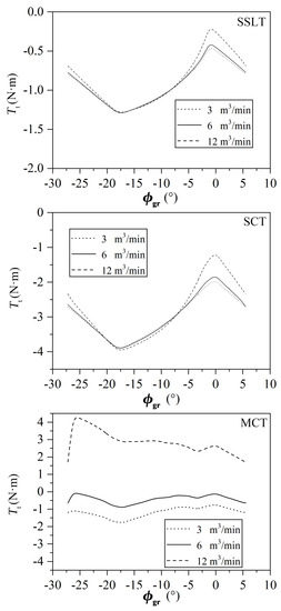
Figure 16.
The total torque of a whole period in different machines.
It can be observed that total torque Tt are always negative for SSLT and SCT. For MCT, Tt are negative in 3 and 6 m3·min−1 machines. However, in the 12 m3·min−1 machine, Tt presents positive in the whole period.
It can be easily found that for any definite MPP, total torque Tt increases with the machine size in the studied range. Taking the SCT as an example, the peak value of Tt increases from −1.93 N·m to −1.13 N·m when the discharge capacity raises from 3 m3·min−1 to 12 m3·min−1. It proves that Ta increases more quickly than Tb as the machine size raises. For MCT, the Tt curve rises much more rapidly than the other two MPPs as the machine size is enlarged. This is mainly because the MCT has the largest wedge at leading side.
It can also be found that in the machines of the same discharge capacity, the MCT often has the maximum Tt and the SCT has the minimum Tt. In the 12 m3·min−1 machines, the peak value of −1.13 N·m, −0.195 N·m and 4.37 N·m for the SCT, SSLT and MCT, respectively. In MCT, Tt is positive and the load Tt will be borne by the water films at trailing sides. Although 4.37 N·m> |−1.13| N·m, the water film stiffness of the trailing side is often higher than that in the leading side. Therefore, it is still difficult to judge which MPP has the best performance.
3.3.2. Water Film Stiffness
Total torque Tt is calculated in the range of −δlim to δlim under the gate-rotor rotating angle φgr0 when one of the teeth just closes the screw groove. The numerical results are shown in Figure 17.
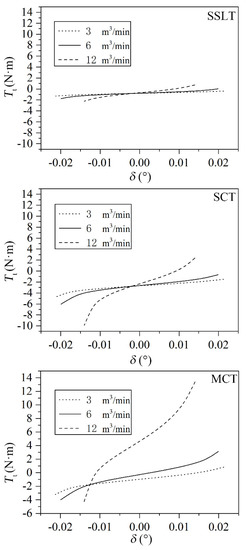
Figure 17.
The total torque at various deflecting angles in different machines.
It is found that Tt increases with δ increasing, which is consistent with that found in Figure 12. It can also be observed that the machine of big discharge capacity has the larger variation range of Tt. Taking MCT for example, the variation range of Tt are −3.22~0.82 N·m, −3.99~3.14 N·m, −4.26~13.41 N·m for 3 m3·min−1, 6 m3·min−1 and 12 m3·min−1 machines, respectively. It implies that for the machine with big size, the self-regulating system is easier to be constituted. It is mainly due to the higher relative velocity and larger hydrodynamic water film in the SSC of big size.
The SCT can establish the self-regulating system only in 12 m3·min−1 SSC. The SSLT can build the self-regulating system in both 6 m3·min−1 and 12 m3·min−1 SSC. The MCT can form this in all the three SSCs. By derivation of the Tt curves in Figure 17, the curves of the water film stiffness S are obtained and shown in Figure 18.
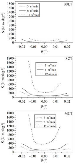
Figure 18.
The water film stiffness in different machines.
It is found that the water film stiffness firstly decreases and then increases as δ increases. The curve shape helps to prevent contact since the stiffness is big at both ends but small in the middle. The water film stiffness S at δ=−δlim (trailing side) is often larger than that at δ = +δlim (leading side). This is consistent with the phenomenon that wear at leading side is more serious than that at trailing side.
For any MPP, the water film stiffness increases with the discharge capacity increasing. This implies that the relative velocity has significant impact on the water film stiffness. The water film stiffness is not in a linear relation with the discharge capacity. Taking the MCT as an example, the water film stiffness S(δ=δlim) of the 6 m3·min−1 and 12 m3·min−1 machines raises by 160.84% and 695.01% compared to the 3 m3·min−1 machine.
3.3.3. MDMT Calculation Results
The calculation results of MDMT in machines of different discharge capacity are shown in Figure 19.
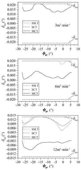
Figure 19.
The MDMT curves in different machines.
In the 3 m3·min−1 SSC, it is found that the MDMT curves of the SSLT and the SCT coincide with the straight line of δ = δlim in a whole period of γ. It implies that |Tb| is always larger than Ta and contact at leading flank is inevitable. It is observed that the MDMT curve of MCT coincides with the straight line of δ = δlim in a small region about 5° (φgr varies from −19.19° to −14.22°). In the remaining region of the whole period, the MDMT curve of MCT does not coincide with δ = δlim anymore. This indicates that wear occurs in part of the period and the water film at leading flank is unable to bear the load of |Tb| in the whole period.
The calculation results of the 6 m3·min−1 SSC under 0.8MPa are shown in Figure 15 and analyzed in Section 3.2.3. In order to facilitate the comparison among the three machines, the calculation results are replotted in Figure 19. It is worth mentioning that in Ref. [20], a 6 m3·min−1 prototype adopting the MCT has been made and a 2000 h endurance test under 0.8MPa has been carried out. In the experiment, the test result does not show any sign of the discharge capacity loss during the whole 2000 h and the tooth flank basically remains in its original shape. The calculated MDMT curve of MCT for the 6 m3·min−1 machine in Figure 19 does not contact with the leading side or with the trailing side in the whole period. The calculated curve is in good agreement with the experimental results.
In the 12 m3·min−1 SSC, it is found that the MDMT curve of the SSLT coincides with the straight line of δ=δlim in a small region about 8.67° (φgr varies from −20.17° to −11.5°). In this range, Ta cannot balance Tb and contact occurs at leading side. The MDMT curve of the SCT reaches δ=δlim when φgr ranges from −18.79° to −13.48°. In the rest range of 27.41°, the SCT MDMT curve is between δlim and -δlim. The MCT MDMT curve does not reach δ = δlim or δ = −δlim in a whole period. It indicates that contact will occur neither at the leading flank nor at the trailing flank. The water films at both sides regulate the gate-rotor effectively. The gate-rotor floats in the water films of both sides.
Overall, in the studied range, with the increment of compressor discharge capacity, the MDMT curves of different MPPs move towards the straight line of δ = −δlim. The liquid films get thicker at the leading side and thinner at the trailing side when δ = δbal. The lubrication performance is improved. The phenomenon that wear occurs at leading flank will reduce. The SSLT and SCT cannot achieve meshing without contact in all of the three SSCs, despite the improvements in the larger machines. The MCT gate-rotor can achieve this goal in the 6 m3·min−1 and 12 m3·min−1 machines.
Further, with increment of the relative velocity, the hydrodynamic effect of leading side increases quicker than that at trailing side. This may mainly be because the relative velocity at tooth tip at leading side is larger than that at trailing side.
3.4. The Fluid Film Lubrication Ratio in a Whole Period
ψ is defined as the ratio of the gate-rotor rotating range in which the meshing pair is lubricated by fluid film to the whole period γ. Based on the calculation results above, the relations between ψ and other lubrication parameters are shown in Figure 20. The influences of discharge pressure and relative velocity vr (machine size) are analyzed, respectively.
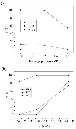
Figure 20.
The fluid film lubrication ratio in a whole period: (a) the influence of discharge pressure, (b) the influence of velocity.
In Figure 20a, the 6 m3·min−1 machine is chosen to analyze the impact of the discharge pressure on ψ. For SSLT, ψ equal to 12.2%, 10.3% and 0 under 0.8MPa, 1.2MPa and 1.6MPa. For SCT, ψ is always a constant of 0. For MCT, ψ equal to 100%, 100% and 54.11% under the three discharge pressure levels. It can be easily observed that along with the discharge pressure increases, ψ decreases for the SSLT and MCT. This indicates that the fluid film lubrication range can be shortened by the increasing pressure and machines with excessive high pressure ratio may not achieve a satisfied life.
In Figure 20b, the discharge pressure is set to 0.8MPa to compare the influence of the relative velocity vr on ψ. For SSLT, ψ equal to 0, 12.22% and 73.51% under 26.3 m·s−1, 31.4 m·s−1 and 40.6 m·s−1. For SCT, ψ varies from 0 to 83.77%. For MCT, ψ increases from 84.81% to 100%. In the studied range, ψ increases with the relative velocity vr. This implies that the fluid film lubrication range can be extended by increasing vr, which can be achieved by the larger machine size or frequency conversion.
4. Conclusions
A theoretical method MDMT for evaluating the MPP’s hydrodynamic lubrication properties of the SSC is proposed in this paper. The main idea of this method is to calculate the micro deflecting motion trajectory of the gate-rotor and judge whether the trajectory crosses the limits. An algorithm is developed to realize the MDMT method. Three MPPs including SSLT, SCT and MCT are evaluated under different working conditions and in different machines. Based on the calculation results, the following conclusions may be made:
- (1)
- The hydrodynamic water film in the MCT meshing pair usually has the highest pressure and action area at tooth flank. In the studied case, compared to the SSLT and SCT, the MCT increases the peak value of the water film pressure by 29.7% and 19.1%, respectively.
- (2)
- The total torque Tt applied the on the gate-rotor decreases with the increment of the discharge pressure and increases with the machine size. The SCT has the minimum Tt among the three MPPs and also the maximum load |Tt | for the water film at leading sides.
- (3)
- The total torque Tt increases with the deflecting angle. With the increment of the discharge pressure and the reduction of the machine size, the self-regulating ability of the gate-rotor declines. The MCT has the strongest self-regulating capability among the three MPPs.
- (4)
- The water film stiffness firstly decreases and then increases when δ increases. The water film stiffness S at trailing side is always larger than that at leading side. The water film stiffness S raises with the discharge pressure and machine size. The relation between S and discharge capacity is unlinear. The MCT has the biggest water film stiffness at the leading side.
- (5)
- As the discharge pressure increases, the MDMT curves approach the leading flank, and the lubrication properties get worse. Under 0.8MPa, the ratios of no contact region to the whole period are 12.2%, 0 and 100% for SSLT, SCT and MCT, respectively. Under 1.2MPa, the ratios decrease to 10.4%, 0 and 100%. Under 1.6MPa, the ratios change to 0, 0 and 54.1%. The MCT shows some high-pressure resistance.
- (6)
- With the machine size increasing, the MDMT curves move towards the trailing side and the lubrication performance is improved. In the 3 m3·min−1 SSCs, the ratios of no contact region to the whole period are 0, 0 and 84.8% for SSLT, SCT and MCT, respectively. In the 6 m3·min−1 SSCs, the ratios raise to 12.2%, 0 and 100%. In the 12 m3·min−1 SSCs, the ratios further increase to 73.51%, 83.75% and 100%. In small machines, the MCT can still keep relative high lubrication performance.
- (7)
- The MDMT method is an intuitive and effective method to evaluate the MPPs of SSCs comprehensively.
To verify the MDMT method accurately by experiment is an interesting work in the future. In addition, this study can lay a foundation for improving the existing thermodynamic model since the gate-rotor is always set to no deflection when calculating the leakage through the gaps at tooth flanks.
Author Contributions
Project administration and conceptualization, D.C.; methodology, T.L.; formal analysis, W.J.; visualization and supervision, X.G.; data curation, T.L. and W.J.; software, R.H.; funding acquisition, T.L. and R.H.; resources, investigation and validation, Q.F.; writing—original draft, T.L. All authors have read and agreed to the published version of the manuscript.
Funding
This research was funded by the Fundamental Research Funds for the Central Universities (GrantNo. 2452017319), Science and Technology Project of Shaanxi Provincial Water Resources Department (Grant No.2019slkj-17), the National Natural Science Foundation of China (Grant No. 51706179).
Conflicts of Interest
The authors declare no conflict of interest.
References
- Quanke, F.; Jia, X.; Wenshan, Z. The twist of unfortunate fate and suspension meshing technology with liquid injection in single screw compressors. Compress. Technol. 2016, 6, 6–10. (In Chinese) [Google Scholar]
- Li, T.; Liu, Z.; Huang, R.; Liu, F.-L.; Feng, Q.-K.; Yu, X.-L. Research of the hydrodynamic lubrication characteristics of different MPPs in water-flooded single screw compressors. Proc. Inst. Mech. Eng. Part A J. Power Energy 2016, 230, 247–259. [Google Scholar] [CrossRef]
- Zimmern, B. Positive Displacement Machine with a Plastic Gate Pinion. U.S. Patent 4,890,989, 2 January 1990. [Google Scholar]
- Jin, G.X.; Deng, D.G. Improvement of the reliability of a single screw compressor. In Proceedings of the International Compressor Engineering Conference at Purdue, West Lafayette, IN, USA, 11–13 July 1984; pp. 293–296. [Google Scholar]
- Zimmern, B. From water to refrigerant: Twenty years to develop the oil injection-free single screw compressor. In Proceedings of the International Compressor Engineering Conference at Purdue, West Lafayette, IN, USA, 11–13 July 1984; pp. 513–518. [Google Scholar]
- Wen, S.Z.; Huang, P. Principles of Tribology; John Wiley: Hoboken, NJ, USA, 2017. [Google Scholar]
- Feng, Q.K.; Guo, B.; Zhao, C.; Xu, J.; Li, Y.J.; Shu, P.C. A design method of meshing pair profile of single screw compressors enveloped by multi straight lines. Compress. Technol. 2005, 191, 1–6. (In Chinese) [Google Scholar]
- Wu, W.F.; Feng, Q.K. A multicolumn envelope meshing pair for single screw compressors. J. Mech. Des. Trans. ASME 2009, 131, 31–36. [Google Scholar] [CrossRef]
- Li, J.; Feng, Q.K.; Liu, F.L.; Wu, W. Experimental studies of the tooth wear resistance with different profiles in single screw compressor. Tribol. Int. 2013, 57, 210–215. [Google Scholar] [CrossRef]
- Wang, Z.L.; Wang, H.; Wang, J.; Li, Q.; Feng, Q. Theoretical study on wear characteristics of single screw refrigeration compressor with multicolumn envelope meshing pair. Int. J. Refrig. 2019, 102, 1–11. [Google Scholar] [CrossRef]
- Zimmern, B.; Patel, G.C. Design and operating characteristics of the Zimmern single screw compressor. In Proceedings of the 1972 Purdue Compressor Technology Conference, West Lafayette, IN, USA, 25–27 July 1972; pp. 96–99. [Google Scholar]
- Heidrich, F.L. Water flooded single screw (SSP) compressor technology. In Proceedings of the Purdue Compressor Technology Conference, West Lafayette, IN, USA, 23–26 July 1996; pp. 145–150. [Google Scholar]
- Jin, G.X. A study of the profile and hydrodynamic lubrication of a monoscrew compressor. J. Xi’an Jiaotong Univ. 1982, 16, 75–83. (In Chinese) [Google Scholar]
- Post, W.; Swaans, M. Computer simulation of the hydrodynamic lubrication in a single screw compressor. In Proceedings of the the 1986 International Compressor Engineering Conference at Purdue, West Lafayette, IN, USA, 4–7 August 1986; pp. 334–348. [Google Scholar]
- Post, W. De hydrodynamische Filmsmering in een Glovoide Worm Compressor. Ph.D. Thesis, Eindhoven Unversity of Technology, Eindhoven, The Netherlands, 1983. [Google Scholar]
- Sun, S.; Wu, W.F.; Yu, X.L.; Feng, Q. Analysis of oil film force in single screw compressor. In Proceedings of the 2010 International Compressor Engineering Conference at Purdue, West Lafayette, IN, USA, 12–15 July 2010; pp. 612–613. [Google Scholar]
- Li, T.; Wu, W.F.; Feng, Q.K. Research of wear out-failure of star-wheel teeth in single screw compressors. Compress. Technol. 2009, 218, 16–20. (In Chinese) [Google Scholar]
- Wu, W.F.; Li, J.; Li, T.; Feng, Q.; Yu, X. Research of laminar liquid flow in asymmetric narrow channels. Ind. Lubr. Tribol. 2012, 64, 128–131. [Google Scholar] [CrossRef]
- Huang, R.; Li, T.; Yu, X.L.; Liu, F.L.; Feng, Q.K. An optimizaiton of the star-wheel profile in a single screw compressor. Proc. Inst. Mech. Eng. Part A J. Power Energy 2015, 229, 139–150. [Google Scholar] [CrossRef]
- Li, T.; Huang, R.; Feng, Q.K.; Wu, W.F.; Liu, F.L.; Yu, X.L. Hydrodynamic Lubricating Characteristics of Water Flooded Single Screw Compressors Based on Two Types of MPP. Proc. Inst. Mech. Eng. Part J J. Eng. Tribol. 2016, 230, 1092–1106. [Google Scholar] [CrossRef]
- Jiang, Y.A.; Pi, J.; Zhang, Y.; Jiang, T.; Yang, G.; Shen, Z. Research on the tool tip trajectory deflection control and cutting characteristics of elliptical vibration cutting based on guided wave transmission. Int. J. Adv. Manuf. Technol. 2020, 108, 3101–3117. [Google Scholar] [CrossRef]
- Xie, J.; Chen, J.; Peng, Y.; Zi, Y. A New Concept of Instantaneous Whirling Speed for Cracked Rotor’s Axis Orbit. Appl. Sci. 2019, 9, 4120. [Google Scholar] [CrossRef]
- Liang, P.; Lu, C.; Yang, F.Z. Optimal control simulation of elliptical shaft center orbit with the hydraulic servo system. Proc. Inst. Mech. ENG. Part B J. Eng. Manuf. 2019, 233, 610–624. [Google Scholar] [CrossRef]
- Wang, C.; Xing, Z.W.; Hou, F.; Wu, H.; Yu, Z. Research on axis orbit of the journal bearing lubricated with oil and refrigerant mixtures in a twin-screw refrigeration compressor. Int. J. Refrig. 2018, 90, 1–11. [Google Scholar] [CrossRef]
- Xing, Z. Screw Compressor—Theory, Design and Application; China Machine Press: Beijing, China, 2000. (In Chinese) [Google Scholar]
- Li, J.; Wu, H.; Wang, B.; Xing, Z.; Shu, P. Research on the performance of water-injection twin screw compressor. Appl. Therm. Eng. 2009, 29, 3401–3408. [Google Scholar] [CrossRef]
- Wang, Z.L.; Wang, H.; Qu, Y.; Jiang, W.; Feng, Q. Optimization study on multicolumn envelope meshing pair of single screw compressor based on leakage characteristics. Int. J. Refrig. 2018, 92, 113–124. [Google Scholar] [CrossRef]
- Wang, Z.L.; Wang, Z.B.; Wang, J.; Jiang, W.; Feng, Q. Theoretical and experimental study on thermodynamic performance of single screw refrigeration compressor with Multicolumn Envelope Meshing Pair. Appl. Therm. Eng. 2016, 103, 139–149. [Google Scholar] [CrossRef]
- Wang, Z.L.; Liu, Z.; Wang, H.; Wang, J.; Feng, Q.; Li, Q. Geometric characteristics analysis for inner surface of working chamber in single screw compressor with multicolumn envelope meshing pair. Int. J. Refrig. 2019, 108, 347–357. [Google Scholar] [CrossRef]
- Wang, Z.; Wang, H.; Wang, Z.; Li, Q.; Feng, Q. Theoretical study on heat transfer characteristics of single screw refrigeration compressor with Multicolumn envelope meshing pair. Appl. Therm. Eng. 2020, 166, 114635. [Google Scholar] [CrossRef]
- Lu, Y.; Liu, S.; Wu, Y.; Lei, B.; Zhi, R.; Wen, Q.; Ma, C. Performance Improvement of Single Screw Compressor by Meshing Clearance Adjustment Used in Refrigeration System. J. Therm. Sci. 2020. [Google Scholar] [CrossRef]
- Wang, C.; Xing, Z.; Chen, W.; Sun, S.; He, Z. Analysis of the leakage in a water-lubricated twin-screw air compressor. Appl. Therm. Eng. 2019, 155, 217–225. [Google Scholar] [CrossRef]
- Bein, T.W.; Hamilton, J.F. Computer modelinq of an oil flooded single screw air compressor. In Proceedings of the 1982 Purdue Compressor Technology Conference, West Lafayette, IN, USA, 21–23 July 1982; pp. 127–134. [Google Scholar]
- Boblitt, W.W.; Moore, J. Computer modeling of single-screw oil flooded refrigerant compressors. In Proceedings of the 1984 International Compressor Engineering Conference at Purdue, West Lafayette, IN, USA, 11–13 July 1984; pp. 559–567. [Google Scholar]
- Wu, J.H.; Jin, G.X.; Shu, P.C. Investigation on international leakages in single screw compressors and their effects on performance of the compressor. J. Xi’an Jiaotong Univ. 1996, 30, 66–71. (In Chinese) [Google Scholar]
- Chen, Z. Study on Friction and Wear Property and Lubricant Mechanism of Water Lubricated Bearing. Ph.D. Thesis, Chongqing University, Chongqing, China, 2003. (In Chinese). [Google Scholar]
- Xu, S.L.; Zhang, S.H.; Jin, R.T.; Li, Y.M. Study on hydrophilicity of electrolytic copper foil. Nonferrous Met. Process. 2006, 35, 1–6. [Google Scholar]
- Sun, H.; Yu, Q.S.; Yang, B.; Xu, G.Z. Surface hydrophilic modification of Poly (ether ether kenote) and immobilization of collagen. Chem. J. Chin. Univ. 2016, 37, 1154–1160. (In Chinese) [Google Scholar]
- Launder, B.E.; Leschziner, M. Flow in finite-width, thrust bearings including inertial effects I-laminar flow. J. Lubr. Technol. Trans. ASME 1978, 100, 330–338. [Google Scholar] [CrossRef]
- Li, K.Y.; Chen, G.D.; Liu, D. Study of the influence of lubrication parameters on gear lubrication properties and efficiency. Ind. Lubr. Tribol. 2016, 68, 647–657. [Google Scholar] [CrossRef]
- Jisheng, E.; Gawne, D.T. Influence of lubrication regime on the sliding wear behaviour of an alloy steel. Wear 1997, 211, 1–8. [Google Scholar] [CrossRef]
- Cheng, D.X. Handbook of Mechanical Design; Chemical Industry Press: Beijing, China, 2016. (In Chinese) [Google Scholar]
- Li, T.; Wang, Z.; Huang, R. Theoretical analysis of loads on the gate rotor bearings in the single screw compressor. In Proceedings of the 8th International Conference on Compressors and Their Systems, London, UK, 9–10 September 2013; pp. 219–225. [Google Scholar]


© 2020 by the authors. Licensee MDPI, Basel, Switzerland. This article is an open access article distributed under the terms and conditions of the Creative Commons Attribution (CC BY) license (http://creativecommons.org/licenses/by/4.0/).