Experimental Characterization and Finite Element Modeling of the Effects of 3D Bioplotting Process Parameters on Structural and Tensile Properties of Polycaprolactone (PCL) Scaffolds


Abstract
:1. Introduction
2. Materials and Methods
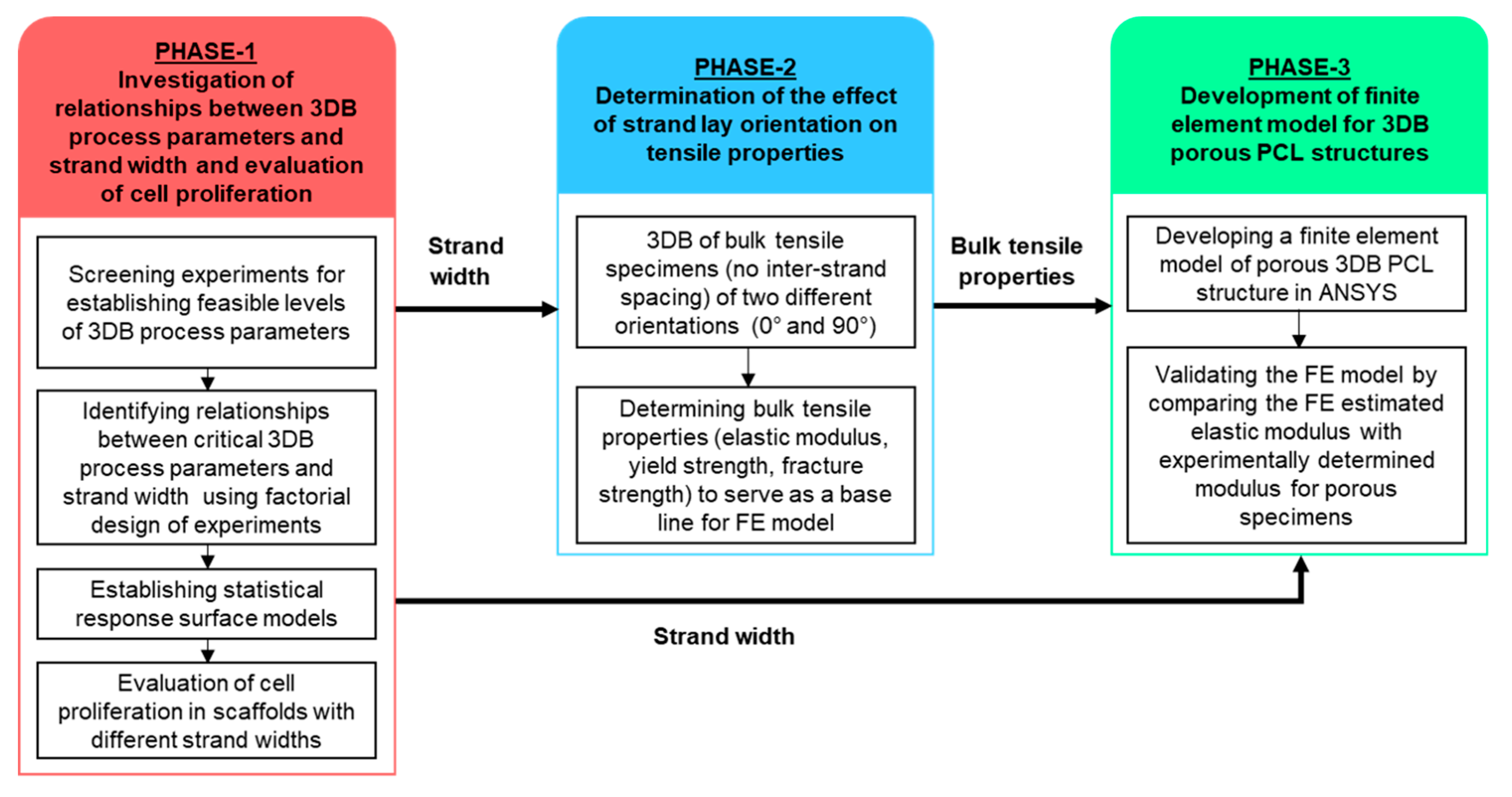
2.1. Phase-1: Investigating Relationships between 3D Bioplotting Parameters, Strand Width, and Cell Proliferation
2.1.1. 3D Bioplotting Parameter Screening
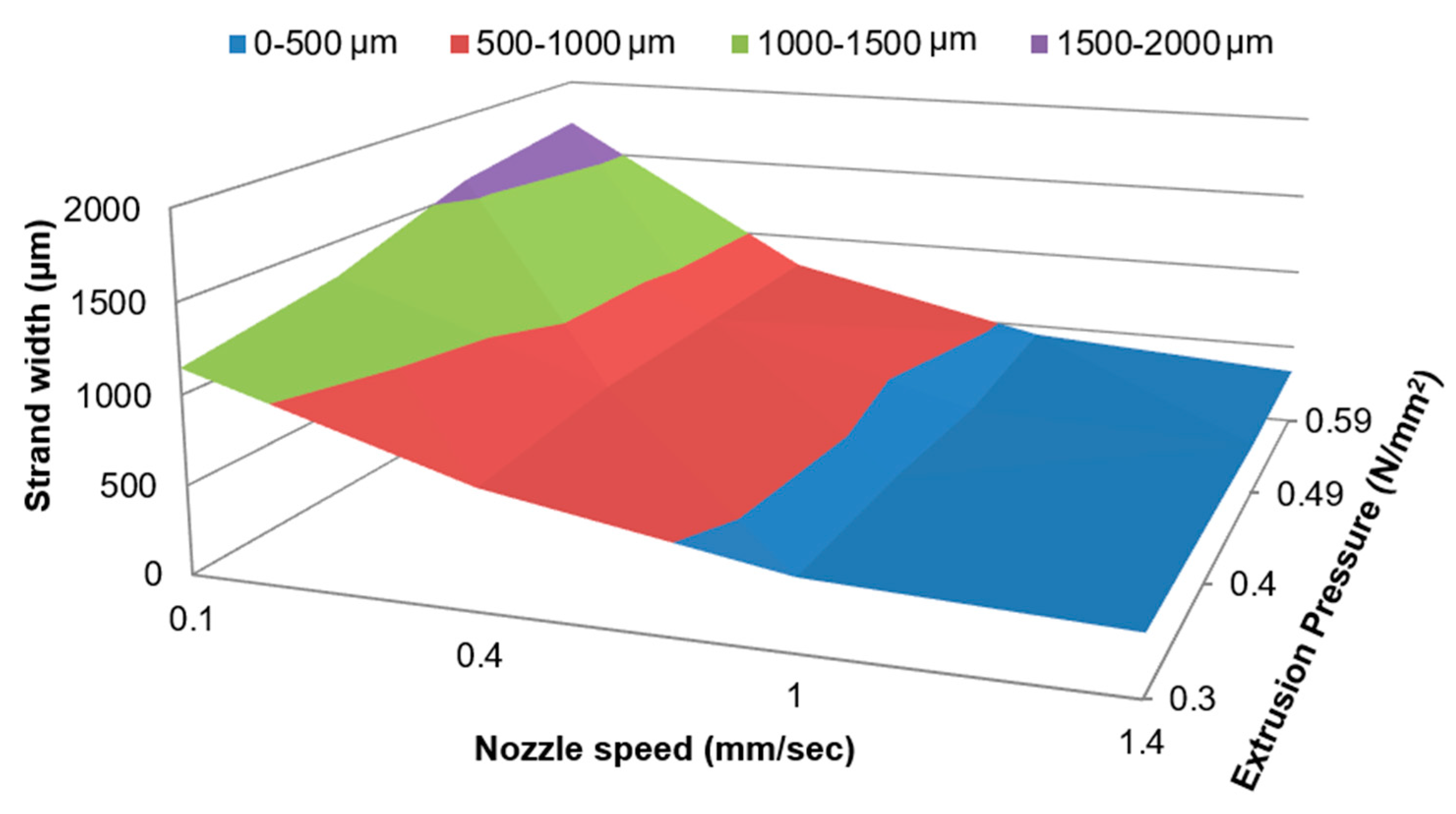
2.1.2. Factorial Design of Experiments
2.1.3. Statistical Analyses and Model Validation
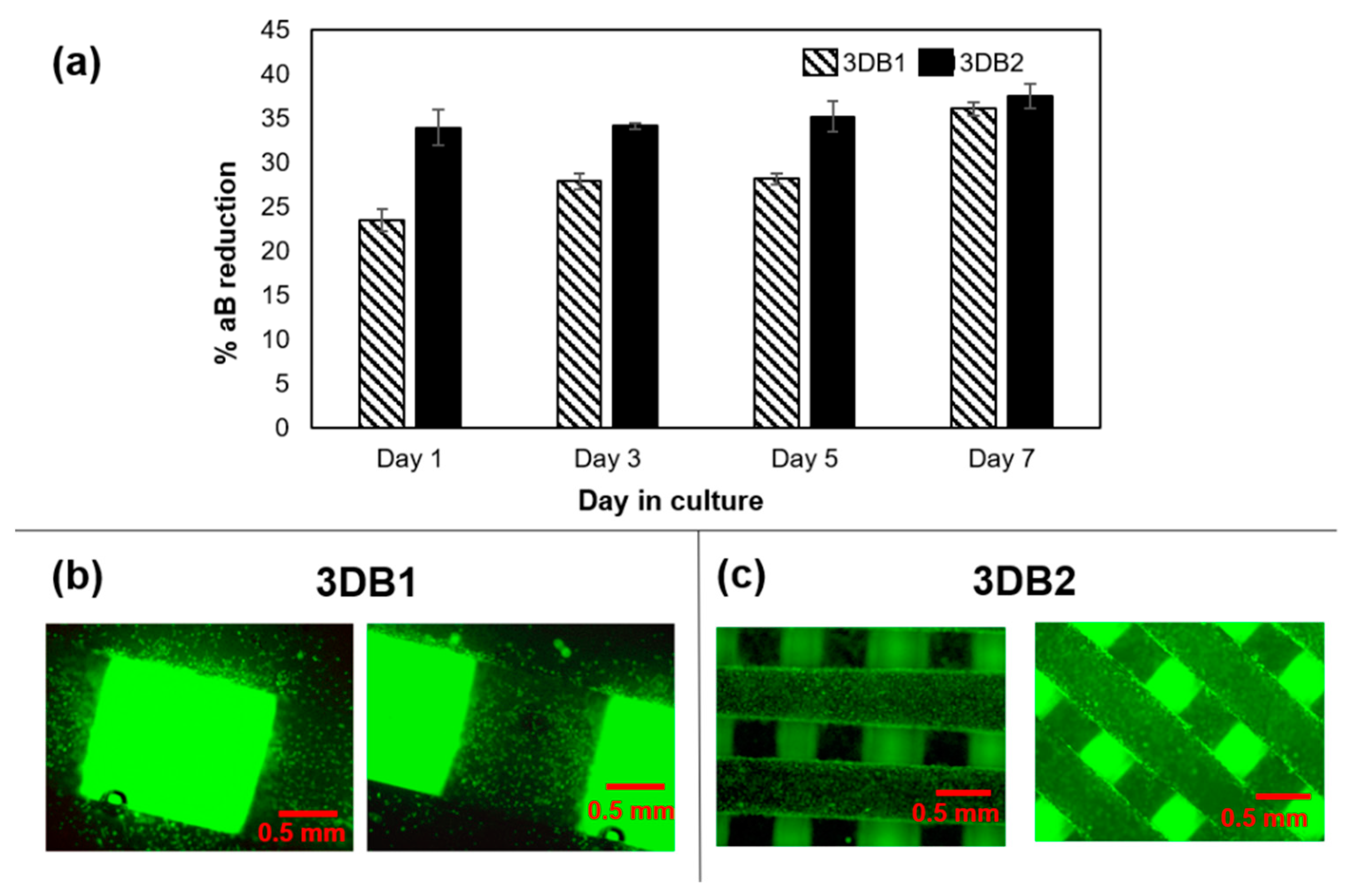
2.1.4. 3D Bioplotting of Porous Scaffolds for Evaluating Cellular Activity
2.1.5. Cell Expansion and Seeding of Scaffolds
2.1.6. Cell Proliferation Assays
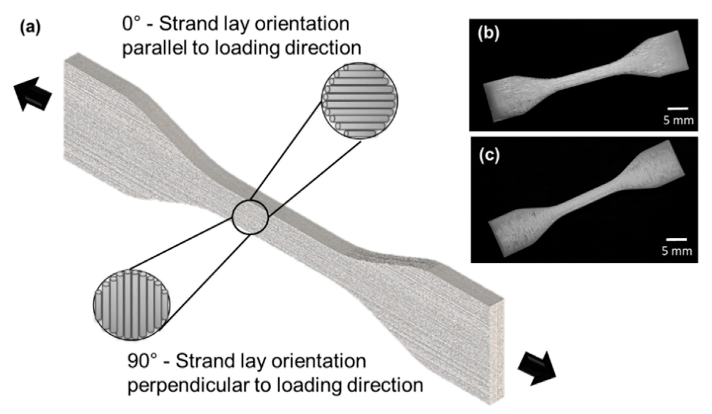
2.2. Phase-2: Determining the Effect of Strand Lay Orientation on Tensile Properties of Bioplotted PCL
2.2.1. 3D Bioplotting of Bulk PCL Tensile Specimens
2.2.2. Tensile Testing
2.2.3. Statistical Analysis
2.3. Phase-3: Developing and Validating a Finite Element Model for Bioplotted PCL
3. Results
3.1. Phase-1: Relationships between 3D-Bioplotting Parameters, Strand Width, and Cell Proliferation
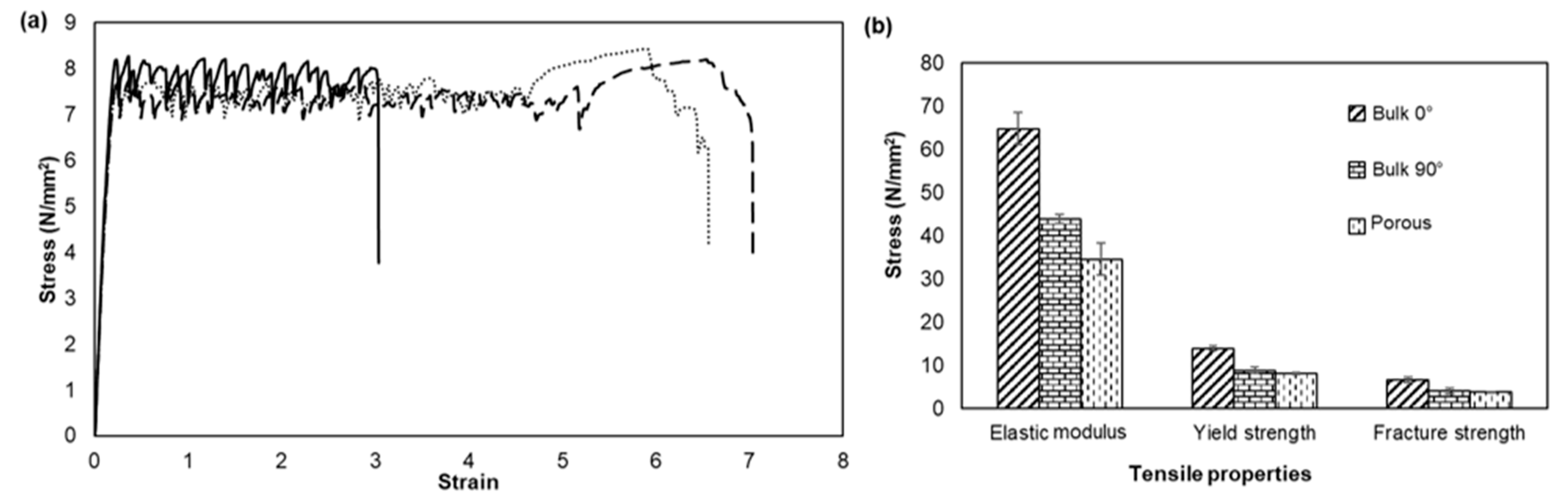
3.2. Phase-2: Effect of Strand lay Orientation on Tensile Properties of Bioplotted PCL
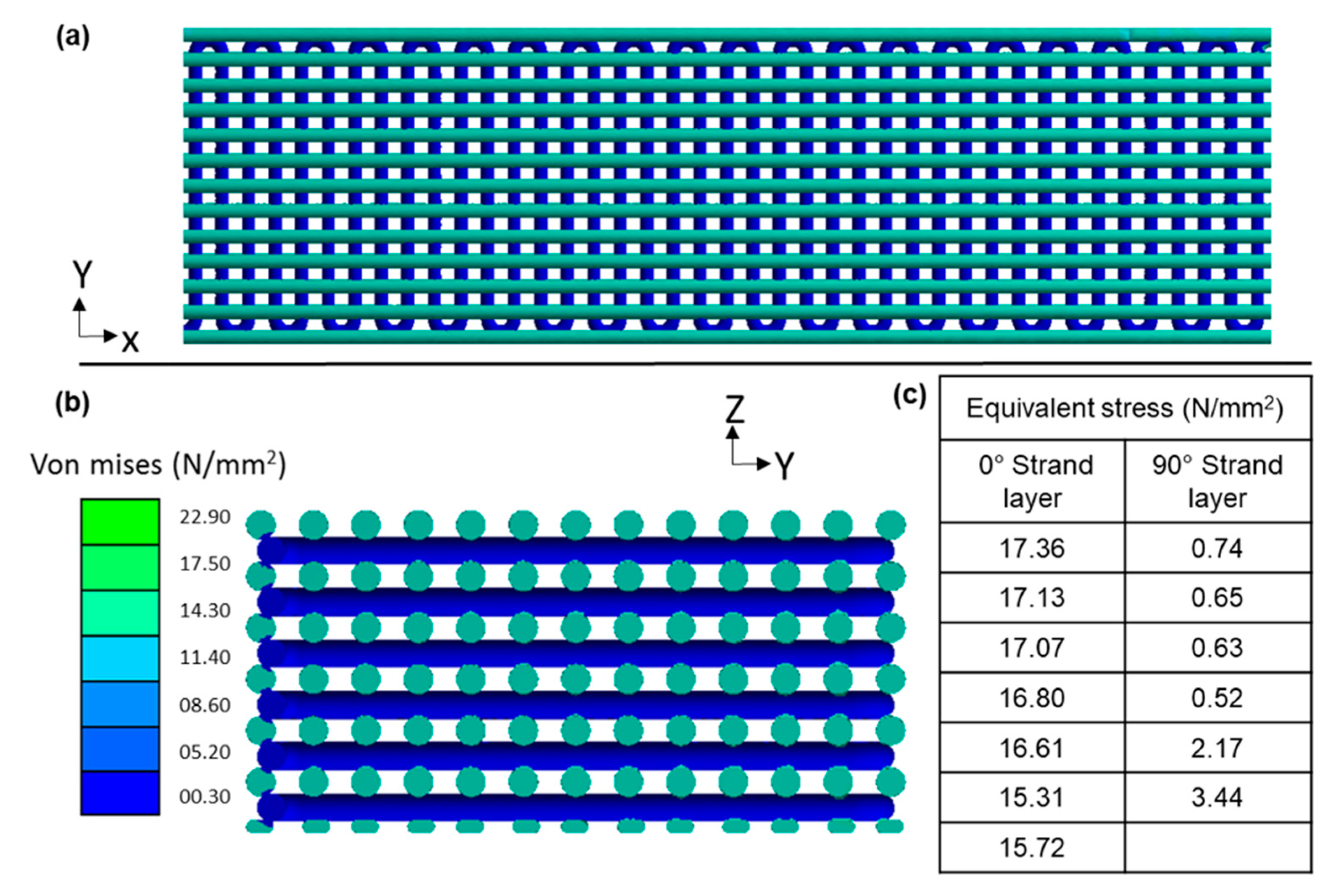
3.3. Phase-3: Finite Element Modeling and Validation
4. Discussion
5. Conclusions
Supplementary Materials
Author Contributions
Funding
Acknowledgments
Conflicts of Interest
References
- Lanza, R.P.; Langer, R.; Vacanti, J. Principles of Tissue Engineering; Elsevier Academic Press: Cambridge, MA, USA, 2007; ISBN 9780080548845. [Google Scholar]
- Fisher, J.P.; Mikos, A.G.; Bronzino, J.D. Tissue Engineering; CRC Press/Taylor & Francis Group: Milton Park, UK, 2007; ISBN 9780849390265. [Google Scholar]
- O’Brien, F.J. Biomaterials & scaffolds for tissue engineering. Mater. Today 2011, 14, 88–95. [Google Scholar] [CrossRef]
- Jafari, M.; Paknejad, Z.; Rad, M.R.; Motamedian, S.R.; Eghbal, M.J.; Nadjmi, N.; Khojasteh, A. Polymeric scaffolds in tissue engineering: A literature review. J. Biomed. Mater. Res. Part. B Appl. Biomater. 2017, 105, 431–459. [Google Scholar] [CrossRef]
- Duan, B.; Wang, M.; Zhou, W.Y.; Cheung, W.L.; Li, Z.Y.; Lu, W.W. Three-dimensional nanocomposite scaffolds fabricated via selective laser sintering for bone tissue engineering. Acta Biomater. 2010, 6, 4495–4505. [Google Scholar] [CrossRef]
- Tan, K.; Chua, C.; Leong, K.; Cheah, C.; Cheang, P.; Abu Bakar, M.; Cha, S. Scaffold development using selective laser sintering of polyetheretherketone–hydroxyapatite biocomposite blends. Biomaterials 2003, 24, 3115–3123. [Google Scholar] [CrossRef]
- Yen, H.-J.; Tseng, C.-S.; Hsu, S.; Tsai, C.-L. Evaluation of chondrocyte growth in the highly porous scaffolds made by fused deposition manufacturing (FDM) filled with type II collagen. Biomed. Microdevices 2009, 11, 615–624. [Google Scholar] [CrossRef]
- Zein, I.; Hutmacher, D.W.; Tan, K.C.; Teoh, S.H. Fused deposition modeling of novel scaffold architectures for tissue engineering applications. Biomaterials 2002, 23, 1169–1185. [Google Scholar] [CrossRef]
- Carvalho, C.; Landers, R.; Hübner, U.; Schmelzeisen, R.; Mülhaupt, R. Fabrication of soft and hard biocompatible scaffolds using 3D-Bioplotting. In Virtual Modelling and Rapid Manufacturing-Advanced Research in Virtual and Rapid Prototyping; Taylor & Francis Group: London, UK, 2005; pp. 97–102. [Google Scholar]
- Narayanan, L.K.; Huebner, P.; Fisher, M.B.; Spang, J.T.; Starly, B.; Shirwaiker, R.A. 3D-Bioprinting of Polylactic Acid (PLA) Nanofiber–Alginate Hydrogel Bioink Containing Human Adipose-Derived Stem Cells. ACS Biomater. Sci. Eng. 2016, 2, 1732–1742. [Google Scholar] [CrossRef]
- Sheshadri, P.; Shirwaiker, R.A. Characterization of Material—Process—Structure Interactions in the 3D Bioplotting of Polycaprolactone. 3D Print. Addit. Manuf. 2015. [Google Scholar] [CrossRef]
- Cooke, M.N.; Fisher, J.P.; Dean, D.; Rimnac, C.; Mikos, A.G. Use of stereolithography to manufacture critical-sized 3D biodegradable scaffolds for bone ingrowth. J. Biomed. Mater. Res. 2003, 64B, 65–69. [Google Scholar] [CrossRef] [PubMed]
- Elomaa, L.; Teixeira, S.; Hakala, R.; Korhonen, H.; Grijpma, D.W.; Seppälä, J.V. Preparation of poly(ε-caprolactone)-based tissue engineering scaffolds by stereolithography. Acta Biomater. 2011, 7, 3850–3856. [Google Scholar] [CrossRef] [PubMed]
- Gómez-Lizárraga, K.K.; Flores-Morales, C.; Del Prado-Audelo, M.L.; Álvarez-Pérez, M.A.; Piña-Barba, M.C.; Escobedo, C. Polycaprolactone- and polycaprolactone/ceramic-based 3D-bioplotted porous scaffolds for bone regeneration: A comparative study. Mater. Sci. Eng. C 2017, 79, 326–335. [Google Scholar] [CrossRef] [PubMed]
- Naghieh, S.; Sarker, M.; Karamooz-Ravari, M.; McInnes, A.; Chen, X. Modeling of the Mechanical Behavior of 3D Bioplotted Scaffolds Considering the Penetration in Interlocked Strands. Appl. Sci. 2018, 8, 1422. [Google Scholar] [CrossRef] [Green Version]
- Leferink, A.M.; Hendrikson, W.J.; Rouwkema, J.; Karperien, M.; van Blitterswijk, C.A.; Moroni, L. Increased cell seeding efficiency in bioplotted three-dimensional PEOT/PBT scaffolds. J. Tissue Eng. Regen. Med. 2016, 10, 679–689. [Google Scholar] [CrossRef] [PubMed]
- Ramanath, H.S.; Chua, C.K.; Leong, K.F.; Shah, K.D. Melt flow behaviour of poly-epsilon-caprolactone in fused deposition modelling. J. Mater. Sci. Mater. Med. 2008, 19, 2541–2550. [Google Scholar] [CrossRef] [PubMed]
- Vozzi, G.; Corallo, C.; Daraio, C. Pressure-activated microsyringe composite scaffold of poly(l-lactic acid) and carbon nanotubes for bone tissue engineering. J. Appl. Polym. Sci. 2013, 129, 528–536. [Google Scholar] [CrossRef]
- Ahn, S.; Montero, M.; Odell, D.; Roundy, S.; Wright, P.K. Anisotropic material properties of fused deposition modeling ABS. Rapid Prototyp. J. 2002, 8, 248–257. [Google Scholar] [CrossRef] [Green Version]
- Anitha, R.; Arunachalam, S.; Radhakrishnan, P. Critical parameters influencing the quality of prototypes in fused deposition modelling. PART 1 Contain. Pap. Present. Int. Conf. Adv. Mater. Process. Technol. 2001, 118, 385–388. [Google Scholar] [CrossRef]
- Górski, F.; Kuczko, W.; Wichniarek, R. Influence of process parameters on dimensional accuracy of parts manufactured using Fused Deposition Modelling technology. Adv. Sci. Technol. Res. J. 2013, 7, 27–35. [Google Scholar] [CrossRef]
- Eshraghi, S.; Das, S. Mechanical and microstructural properties of polycaprolactone scaffolds with one-dimensional, two-dimensional, and three-dimensional orthogonally oriented porous architectures produced by selective laser sintering. Acta Biomater. 2010, 6, 2467–2476. [Google Scholar] [CrossRef] [Green Version]
- Liu, F.; Vyas, C.; Poologasundarampillai, G.; Pape, I.; Hinduja, S.; Mirihanage, W.; Bartolo, P.J. Process-Driven Microstructure Control in Melt-Extrusion-Based 3D Printing for Tailorable Mechanical Properties in a Polycaprolactone Filament. Macromol. Mater. Eng. 2018, 1800173. [Google Scholar] [CrossRef]
- Gleadall, A.; Visscher, D.; Yang, J.; Thomas, D.; Segal, J. Review of additive manufactured tissue engineering scaffolds: Relationship between geometry and performance. Burns Trauma 2018, 6. [Google Scholar] [CrossRef] [PubMed] [Green Version]
- Narayanan, L.K.; Kumar, A.; Tan, Z.G.; Bernacki, S.; Starly, B.; Shirwaiker, R.A. Alginate Microspheroid Encapsulation and Delivery of MG-63 Cells into Polycaprolactone Scaffolds: A New Biofabrication Approach for Tissue Engineering Constructs. J. Nanotechnol. Eng. Med. 2015, 6, 021003. [Google Scholar] [CrossRef]
- ASTM Standard Test Method for Tensile Properties of Plastics. Available online: https://www.astm.org/Standards/D638.htm (accessed on 14 August 2018).
- Bañobre-López, M.; Piñeiro-Redondo, Y.; De Santis, R.; Gloria, A.; Ambrosio, L.; Tampieri, A.; Dediu, V.; Rivas, J. Poly(caprolactone) based magnetic scaffolds for bone tissue engineering. J. Appl. Phys. 2011, 109, 07B313. [Google Scholar] [CrossRef]
- Park, S.A.; Lee, S.H.; Kim, W.D. Fabrication of porous polycaprolactone/hydroxyapatite (PCL/HA) blend scaffolds using a 3D plotting system for bone tissue engineering. Bioprocess. Biosyst. Eng. 2011, 34, 505–513. [Google Scholar] [CrossRef] [PubMed]
- Williams, J.M.; Adewunmi, A.; Schek, R.M.; Flanagan, C.L.; Krebsbach, P.H.; Feinberg, S.E.; Hollister, S.J.; Das, S. Bone tissue engineering using polycaprolactone scaffolds fabricated via selective laser sintering. Biomaterials 2005, 26, 4817–4827. [Google Scholar] [CrossRef] [PubMed]
- Baji, A.; Mai, Y.-W.; Wong, S.-C.; Abtahi, M.; Chen, P. Electrospinning of polymer nanofibers: Effects on oriented morphology, structures and tensile properties. Compos. Sci. Technol. 2010, 70, 703–718. [Google Scholar] [CrossRef]
- Engelberg, I.; Kohn, J. Physico-mechanical properties of degradable polymers used in medical applications: A comparative study. Biomaterials 1991, 12, 292–304. [Google Scholar] [CrossRef]
- Abu Bakar, M.S.; Cheng, M.H.W.; Tang, S.M.; Yu, S.C.; Liao, K.; Tan, C.T.; Khor, K.A.; Cheang, P. Tensile properties, tension–tension fatigue and biological response of polyetheretherketone–hydroxyapatite composites for load-bearing orthopedic implants. Biomaterials 2003, 24, 2245–2250. [Google Scholar] [CrossRef]
- Pfister, A.; Landers, R.; Laib, A.; Hübner, U.; Schmelzeisen, R.; Mülhaupt, R. Biofunctional rapid prototyping for tissue-engineering applications: 3D bioplotting versus 3D printing. J. Polym. Sci. Part A Polym. Chem. 2004, 42, 624–638. [Google Scholar] [CrossRef]
- Murphy, C.M.; Haugh, M.G.; O’Brien, F.J. The effect of mean pore size on cell attachment, proliferation and migration in collagen–glycosaminoglycan scaffolds for bone tissue engineering. Biomaterials 2010, 31, 461–466. [Google Scholar] [CrossRef]
- Van De Velde, K.; Kiekens, P. Biopolymers: Overview of several properties and consequences on their applications. Polym. Test. 2002, 21, 433–442. [Google Scholar] [CrossRef]
- Södergård, A.; Stolt, M. Properties of lactic acid based polymers and their correlation with composition. Prog. Polym. Sci. 2002, 27, 1123–1163. [Google Scholar] [CrossRef]
- Hussain, F.; Hojjati, M.; Okamoto, M.; Gorga, R.E. Review article: Polymer-matrix Nanocomposites, Processing, Manufacturing, and Application: An Overview. J. Compos. Mater. 2006, 40, 1511–1575. [Google Scholar] [CrossRef]
- Ku, H.; Wang, H.; Pattarachaiyakoop, N.; Trada, M. A review on the tensile properties of natural fiber reinforced polymer composites. Compos. Part B Eng. 2011, 42, 856–873. [Google Scholar] [CrossRef] [Green Version]
- Lee, C.S.; Kim, S.G.; Kim, H.J.; Ahn, S.H. Measurement of anisotropic compressive strength of rapid prototyping parts. J. Mater. Process. Technol. 2007, 187, 627–630. [Google Scholar] [CrossRef]
- Butscher, A.; Bohner, M.; Hofmann, S.; Gauckler, L.; Müller, R. Structural and material approaches to bone tissue engineering in powder-based three-dimensional printing. Acta Biomater. 2011, 7, 907–920. [Google Scholar] [CrossRef]
- Inzana, J.A.; Olvera, D.; Fuller, S.M.; Kelly, J.P.; Graeve, O.A.; Schwarz, E.M.; Kates, S.L.; Awad, H.A. 3D printing of composite calcium phosphate and collagen scaffolds for bone regeneration. Biomaterials 2014, 35, 4026–4034. [Google Scholar] [CrossRef] [Green Version]
- Bellini, A.; Güçeri, S. Mechanical characterization of parts fabricated using fused deposition modeling. Rapid Prototyp. J. 2003, 9, 252–264. [Google Scholar] [CrossRef]
- Domingos, M.; Intranuovo, F.; Russo, T.; De Santis, R.; Gloria, A.; Ambrosio, L.; Ciurana, J.; Bartolo, P. The first systematic analysis of 3D rapid prototyped poly(ε-caprolactone) scaffolds manufactured through BioCell printing: The effect of pore size and geometry on compressive mechanical behaviour and in vitro hMSC viability. Biofabrication 2013, 5, 045004. [Google Scholar] [CrossRef]
- Biopolymers- Perstorp. Available online: https://www.perstorp.com/en/products/plastic_materials/bioplastics/biopolymers (accessed on 28 July 2020).
- Granado, A.; Eguiazábal, J.I.; Nazábal, J. Structure and mechanical properties of blends of poly(ε-caprolactone) with a poly(amino ether). J. Appl. Polym. Sci. 2008, 109, 3892–3899. [Google Scholar] [CrossRef]
- Pitt, C.G.; Gratzl, M.M.; Kimmel, G.L.; Surles, J.; Schindler, A. Aliphatic polyesters II. The degradation of poly (DL-lactide), poly (epsilon-caprolactone), and their copolymers in vivo. Biomaterials 1981, 2, 215–220. [Google Scholar] [CrossRef]
- Tan, E.P.S.; Ng, S.Y.; Lim, C.T. Tensile testing of a single ultrafine polymeric fiber. Biomaterials 2005, 26, 1453–1456. [Google Scholar] [CrossRef] [PubMed]
- Wong, S.-C.; Baji, A.; Leng, S. Effect of fiber diameter on tensile properties of electrospun poly(ε-caprolactone). Polymer (Guildf.) 2008, 49, 4713–4722. [Google Scholar] [CrossRef]
- Lee, K.H.; Kim, H.Y.; Khil, M.S.; Ra, Y.M.; Lee, D.R. Characterization of nano-structured poly(ε-caprolactone) nonwoven mats via electrospinning. Polymer (Guildf.) 2003, 44, 1287–1294. [Google Scholar] [CrossRef]
- Cahill, S.; Lohfeld, S.; McHugh, P.E. Finite element predictions compared to experimental results for the effective modulus of bone tissue engineering scaffolds fabricated by selective laser sintering. J. Mater. Sci. Mater. Med. 2009, 20, 1255–1262. [Google Scholar] [CrossRef]
- Chemical & Physical Properties of Select Polymers—LACTEL Absorbable Polymers. Available online: http://www.absorbables.com/technical/properties.html (accessed on 13 August 2018).
- Polycaprolactone | Sigma-Aldrich. Available online: http://www.sigmaaldrich.com/catalog/product/sial/81277?lang=en®ion=US (accessed on 28 July 2020).
- Luxner, M.H.; Stampfl, J.; Pettermann, H.E. Finite element modeling concepts and linear analyses of 3D regular open cell structures. J. Mater. Sci. 2005, 40, 5859–5866. [Google Scholar] [CrossRef]
- Kim, G.D.; Oh, Y.T. A benchmark study on rapid prototyping processes and machines: Quantitative comparisons of mechanical properties, accuracy, roughness, speed, and material cost. Proc. Inst. Mech. Eng. Part B J. Eng. Manuf. 2008, 222, 201–215. [Google Scholar] [CrossRef]
- Griffin, E.A.; Mcmillin, S. Selective Laser Sintering and Fused Deposition Modeling Processes for Functional Ceramic Parts. In Proceedings of the Solid Freeform Fabrication (SFF) Symposium, Austin, TX, USA, 1995; pp. 25–30. [Google Scholar]

| Factors | Levels | Print Pattern (All Dimensions in mm) |
|---|---|---|
| Extrusion pressure | 0.3, 0.4, 0.5, 0.6 N/mm2 | 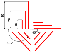 |
| Nozzle speed | 0.1, 0.4, 1.0, 1.4 mm/s | |
| Lay orientation | 0°, 45°, 90°, 135° | |
| Strand length | 10, 20, 30 mm |
| Model Type | Static Structure |
|---|---|
| Material category | Isotropic elasticity |
| Density (g/mm3) | 3.16 × 10⁻⁴ |
| Elastic modulus (N/mm2) | 58.14 |
| Poisson’s ratio | 0.3 |
| Yield Strength (N/mm2) | 12.60 |
| Reference | Molecular Weight (Mw) | Fabrication Process | Geometry | Elastic Modulus (N/mm2) | Yield Strength (N/mm2) |
|---|---|---|---|---|---|
| Manufacturer: Perstorp [44] | 84,500 | Injection molding | n/a | 430 | 17.5 |
| Granado et al. [45] | 80,000 | Injection molding | Sheet | 300 | 14 |
| Engelberg and Kohn [31] | 72,500 | Compression molding | Sheet | 400 | 16 |
| Pitt et al. [46] | 84,500 | Melt extrusion | Dumbbell shaped | 264.8 | n/a |
| Tan et al. [47] | 80,000 | Electrospinning | Single fiber | 120 | 13 |
| Wong et al. [48] | 80,000 | Electrospinning | Sheet | 237 | 14 |
| Lee et al. [49] | 80,000 | Electrospinning | Nonwoven mat | 331 | 56 |
| Eshraghi and Das [22] | 73,000 | SLS | Bulk: solid gage (0°) | 363.4 | 8.2 |
| Eshraghi and Das [22] | 73,000 | SLS | Bulk: solid gage (90°) | 343.9 | 10.1 |
| Cahill et al. [50] | n/a | SLS | Hollow Strut | 47 | n/a |
| Manufacturer – Absorbables [51] | 75,000 | n/a | n/a | 241.3 | 20.6 |
| Manufacturer - Sigma Aldrich [52] | 43,000–80,000 | n/a | n/a | 261.4–400 | 18.6–36.5 |
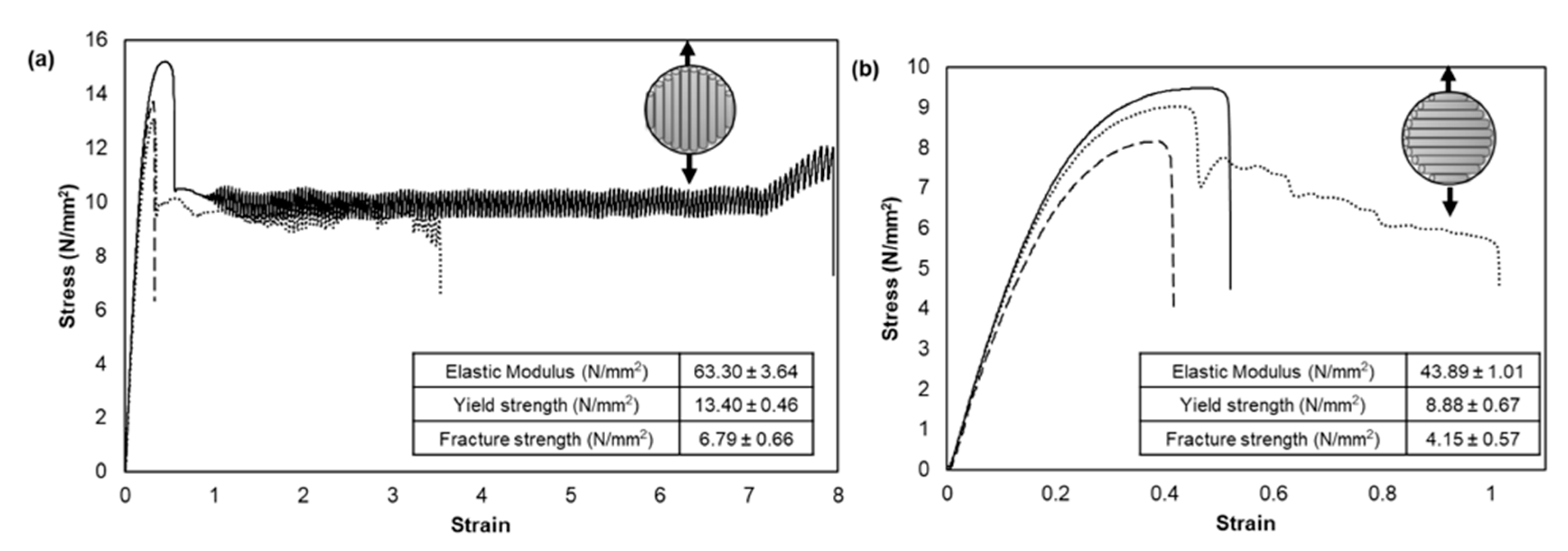
| Narayanan and Shirwaiker | 43,000 | 3DB (Melt extrusion) | Bulk: solid gage (0°) | 63.30 ± 3.64 | 13.40 ± 0.46 |
| Narayanan and Shirwaiker | 43,000 | 3DB (Melt extrusion) | Bulk: solid gage (90°) | 43.89 ± 1.01 | 8.88 ± 0.67 |
© 2020 by the authors. Licensee MDPI, Basel, Switzerland. This article is an open access article distributed under the terms and conditions of the Creative Commons Attribution (CC BY) license (http://creativecommons.org/licenses/by/4.0/).
Share and Cite
Narayanan, L.K.; Shirwaiker, R.A. Experimental Characterization and Finite Element Modeling of the Effects of 3D Bioplotting Process Parameters on Structural and Tensile Properties of Polycaprolactone (PCL) Scaffolds. Appl. Sci. 2020, 10, 5289. https://doi.org/10.3390/app10155289
Narayanan LK, Shirwaiker RA. Experimental Characterization and Finite Element Modeling of the Effects of 3D Bioplotting Process Parameters on Structural and Tensile Properties of Polycaprolactone (PCL) Scaffolds. Applied Sciences. 2020; 10(15):5289. https://doi.org/10.3390/app10155289
Chicago/Turabian StyleNarayanan, Lokesh Karthik, and Rohan A. Shirwaiker. 2020. "Experimental Characterization and Finite Element Modeling of the Effects of 3D Bioplotting Process Parameters on Structural and Tensile Properties of Polycaprolactone (PCL) Scaffolds" Applied Sciences 10, no. 15: 5289. https://doi.org/10.3390/app10155289