Effects of Tilting Pad Journal Bearing Design Parameters on the Pad-Pivot Friction and Nonlinear Rotordynamic Bifurcations


Abstract
:1. Introduction
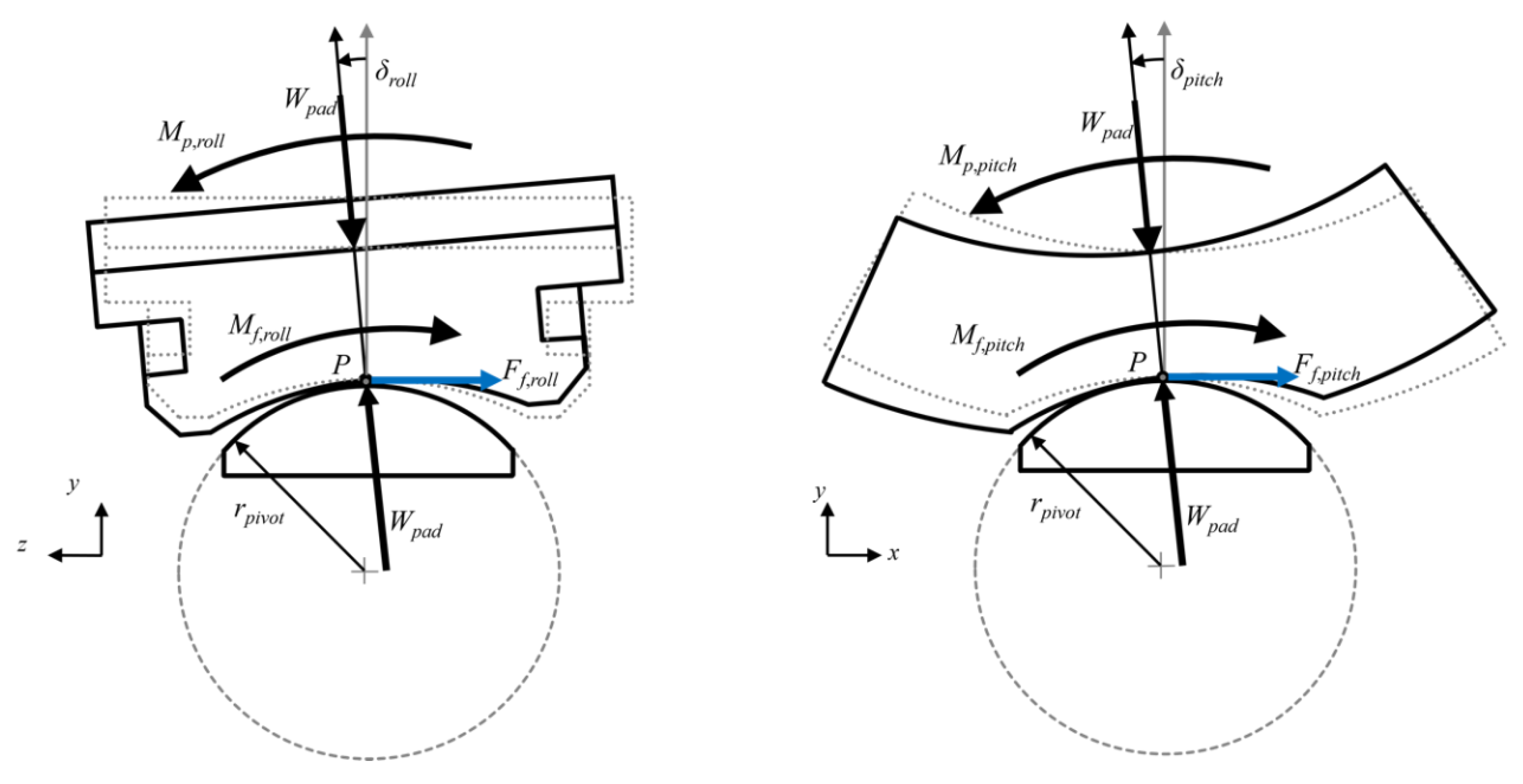
2. Pad-Pivot Friction Mechanism
2.1. Friction Mechanism
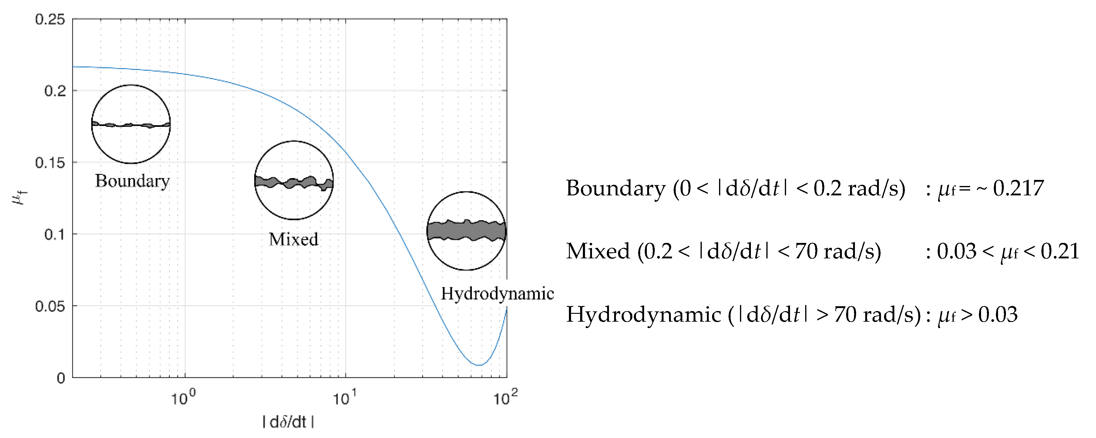
2.2. Stribeck Curve Model (SCM)
3. Rotor-Bearing Model
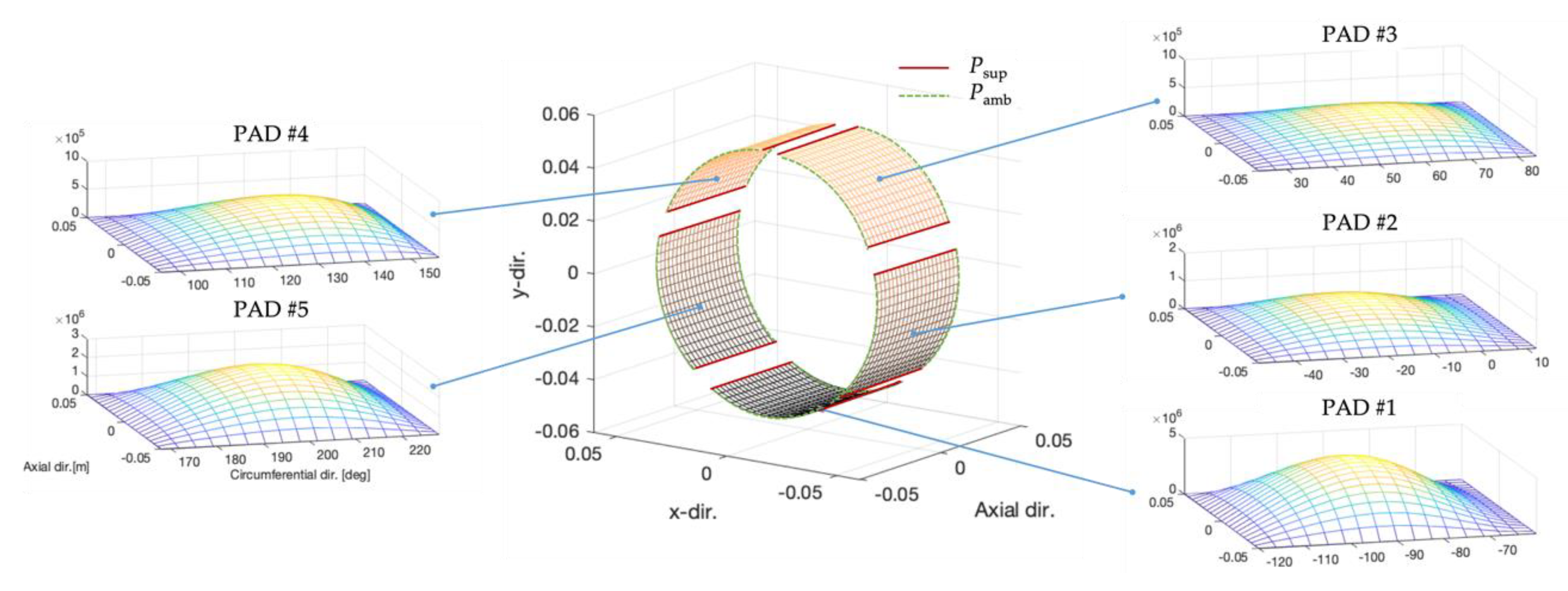
3.1. Five-Pad Tilting Pad Journal Bearing (TPJB)
3.2. Rigid Jeffcott Rotor-TPJB Model
4. Numerical Results
4.1. Anlaysis
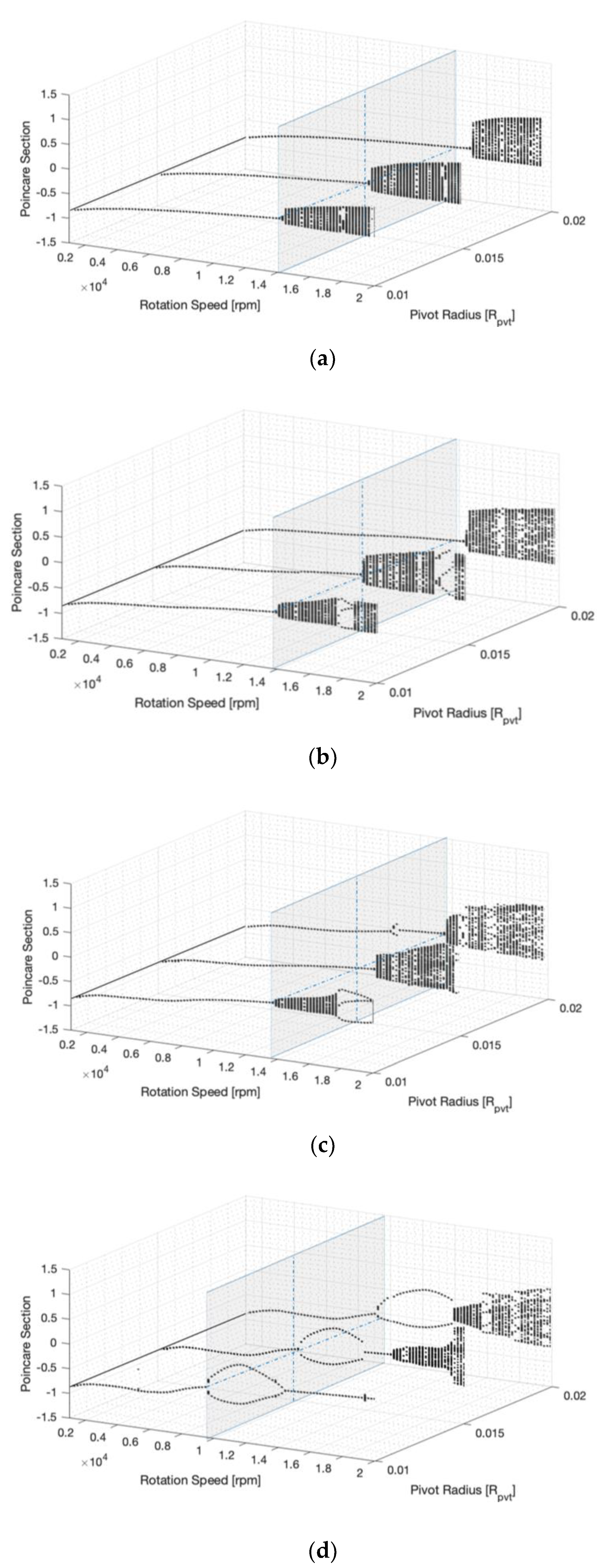
4.1.1. Pivot Radius
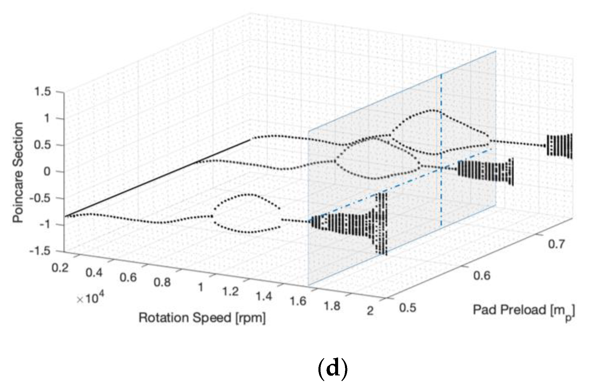
4.1.2. Pad Preload
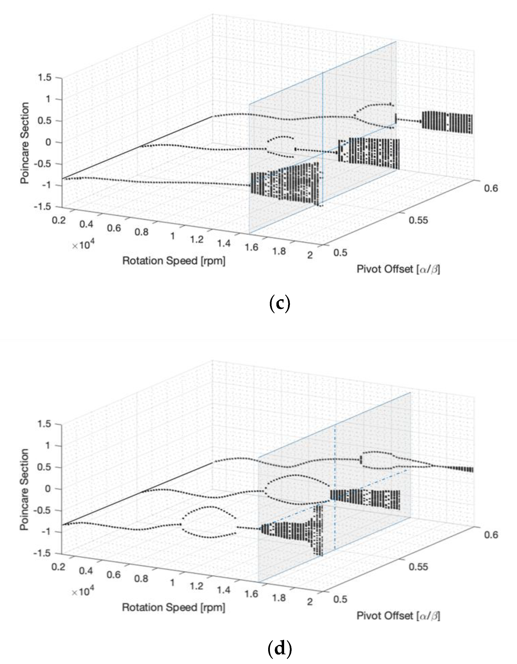
4.1.3. Pivot Offset
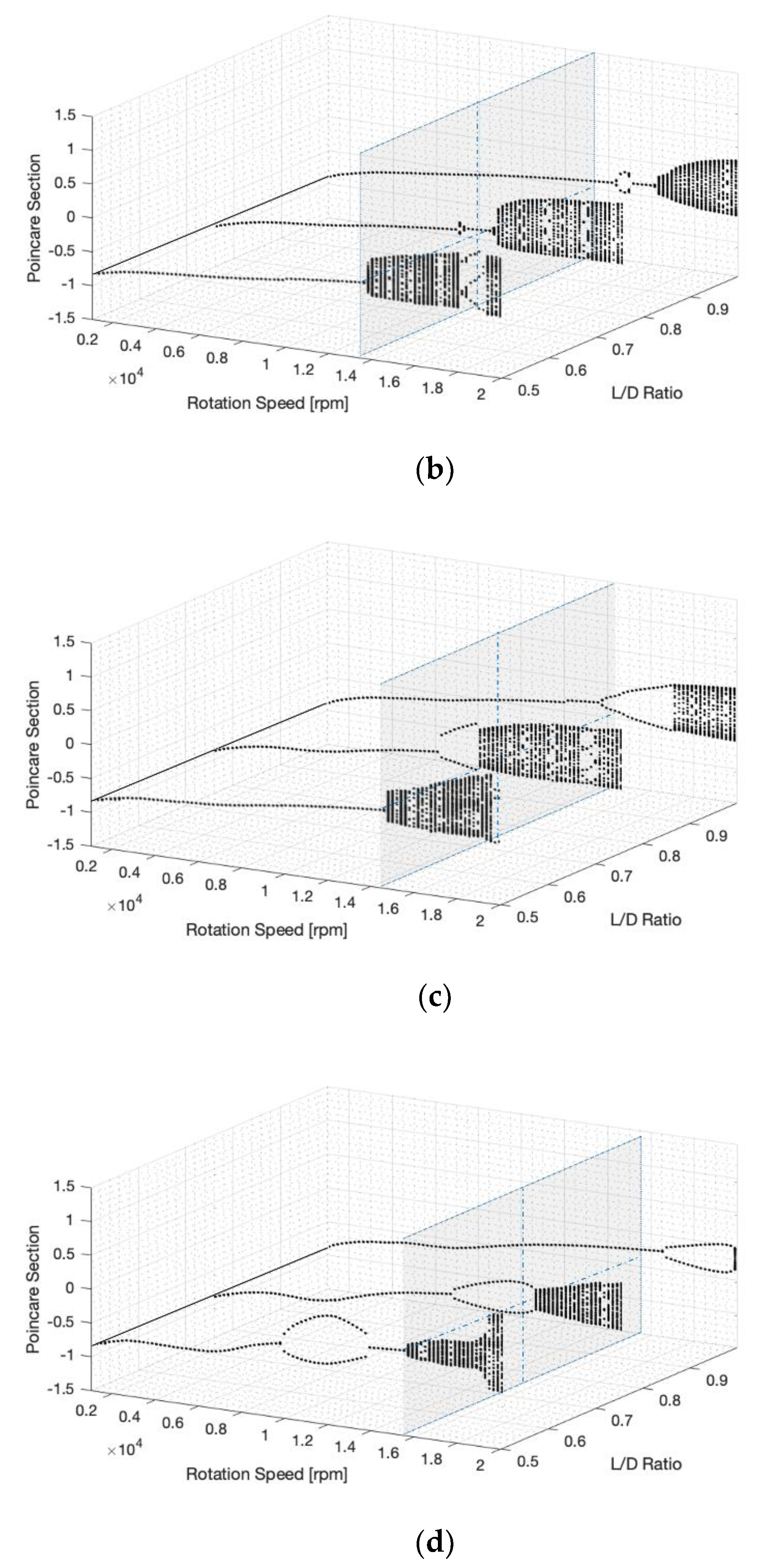
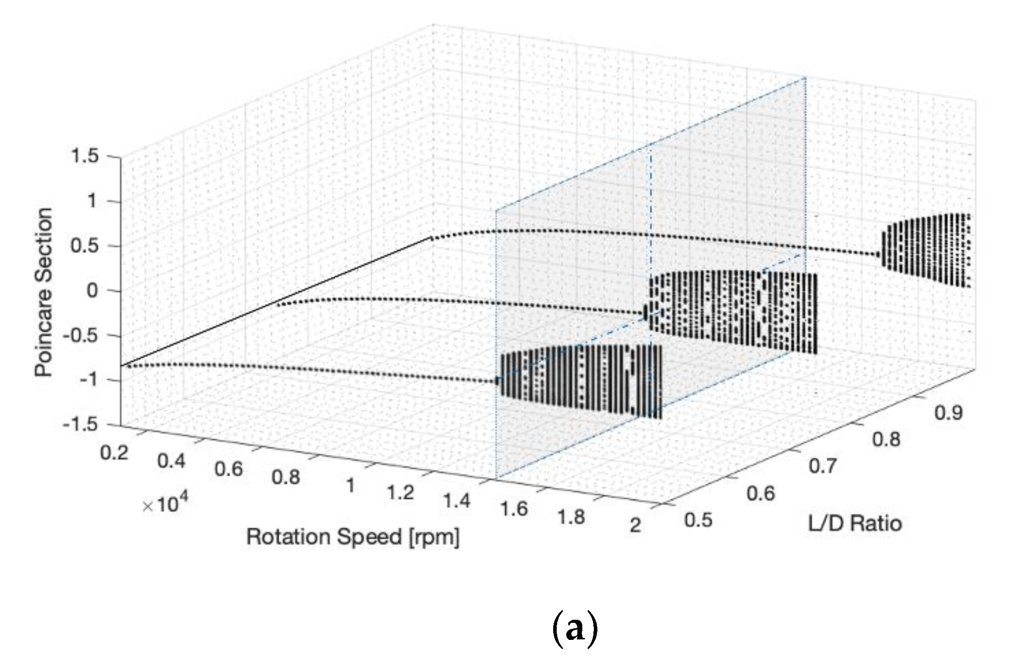
4.1.4. Bearing Length to Diameter (L/D) Ratio
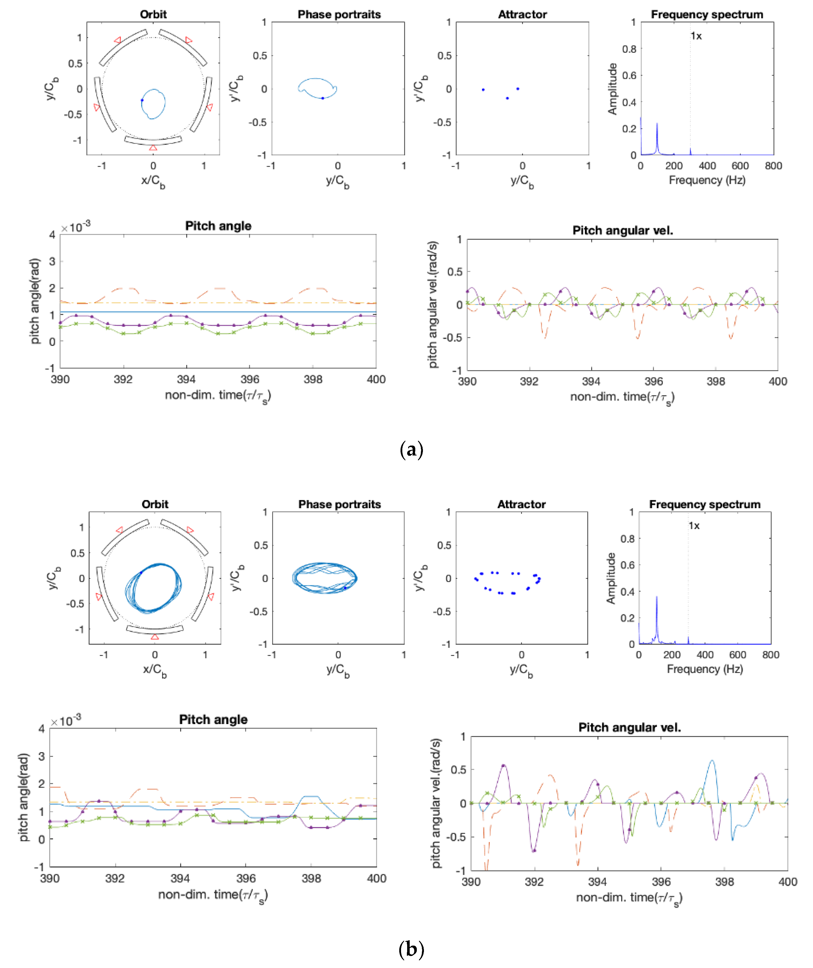
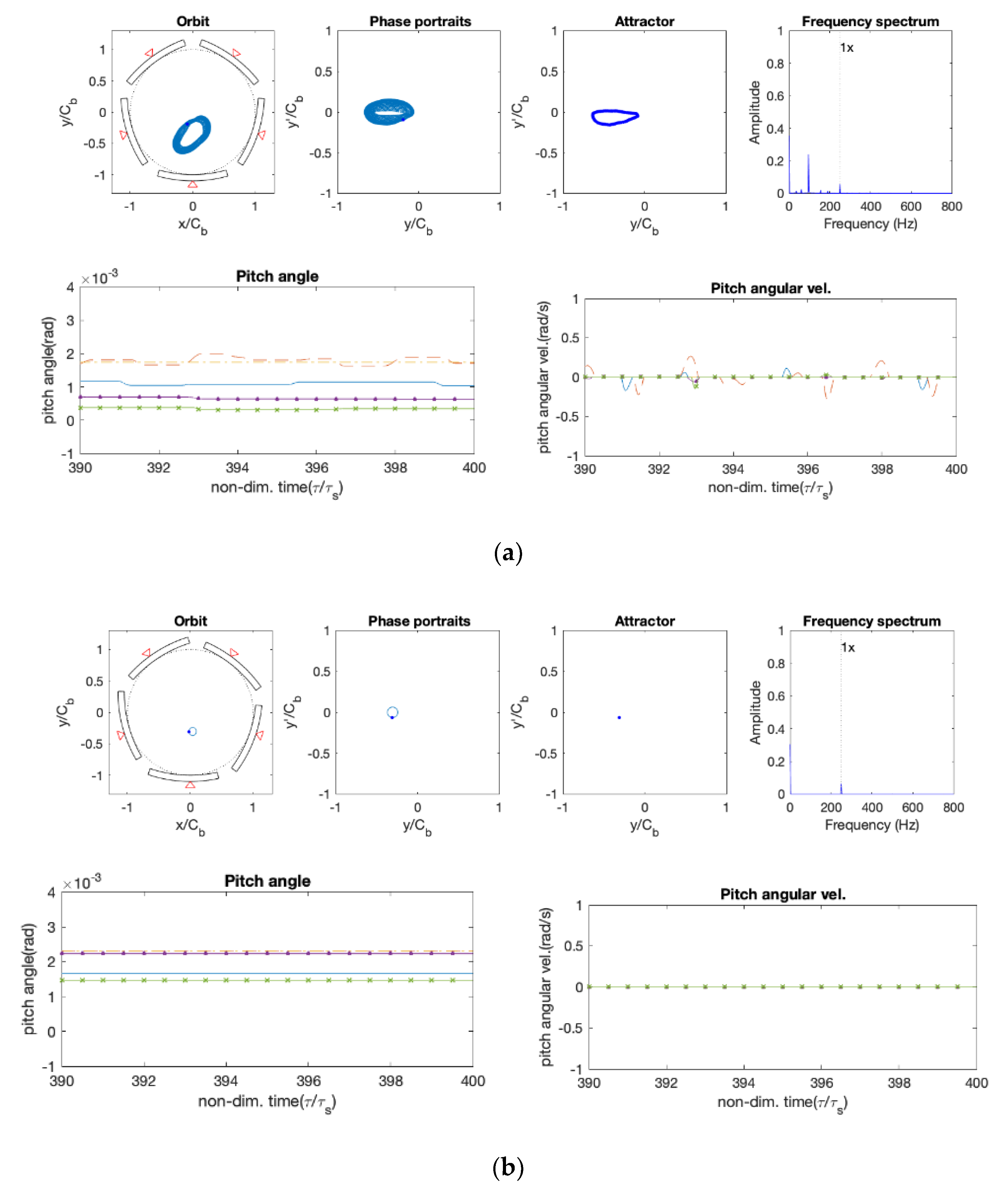
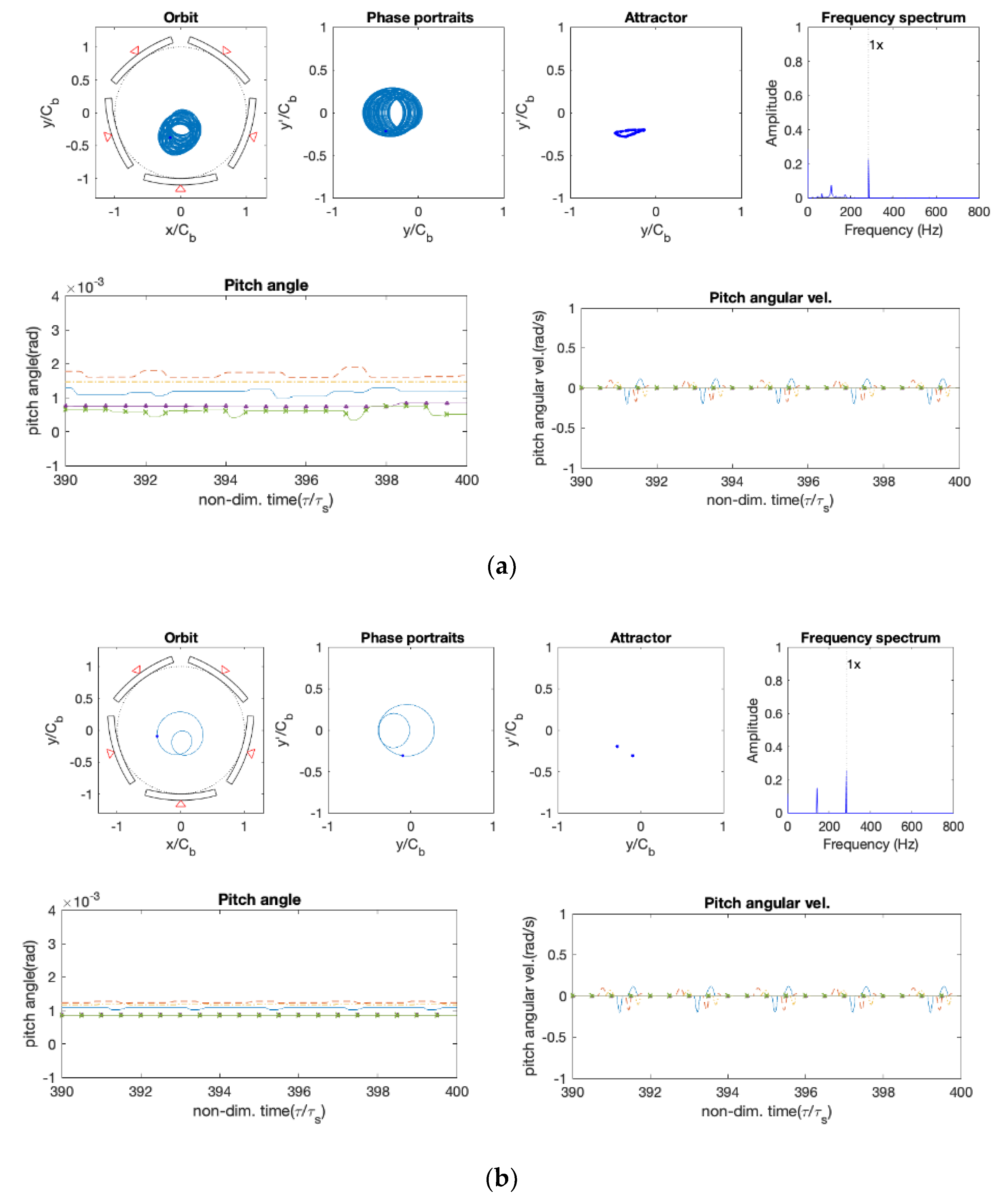
4.2. Orbits and Pad Motions
5. Conclusions
- Pivot radius:
- An increase in the pivot radius induces higher vibration amplitude;
- The Hopf bifurcation event was marginally delayed;
- The higher disc mass eccentricity condition undermined the effect of the pivot radius.
- Pad preload:
- An increase in the pad preload significantly delayed the outbreaks of Hopf bifurcation points;
- The amplitude of the response remained relatively constant;
- In the larger disc unbalance condition, the preload stabilized the instability.
- Pivot offset:
- An increase of the pivot offset delayed the outbreaks of Hopf bifurcation points;
- The amplitude of the response decreased;
- The larger disc mass unbalance undermines the effect of pivot offset.
- L/D ratio:
- A higher L/D ratio tended to stabilize the response; however, it did not display any conspicuous effect. Nevertheless, the fully balanced condition was clearly observed;
- An increase in the disc mass eccentricity undermined the effect of the L/D ratio;
- Nonetheless, a higher L/D ratio led to an enhanced damping effect, which stabilized the quasi-periodic to the 1/2 sub-synchronous responses.
Author Contributions
Funding
Conflicts of Interest
Nomenclature
| Cb | Bearing clearance |
| Cp | Pad clearance |
| D | Bearing diameter |
| Ff | Counter force according to surface friction state |
| h | Film thickness |
| Ip | Pad moment of inertia |
| L | Bearing length |
| mJ | Rotor mass |
| mp | Pad preload |
| Mf | Friction moment |
| Mp | Pad tilting moment |
| p | Hydrodynamic pressure of lubricant film |
| R | Bearing radius |
| Rpvt | Pivot radius |
| Wpad | Normal force on pad |
| Ws | Static load on rotor |
| Wd | Dynamic load on rotor |
| z | Axial position of bearing |
| δ | Tilt angle of pad |
| θ | Angular position of bearing |
| θB | Beginning angle of pad |
| θE | End angle of pad |
| θp | Pivot position in the θ axis |
| μf | Friction coefficient |
| μv | Dynamic viscosity of lubricant oil |
| ω | Angular velocity of journal |
| χp/χ | Pad offset |
References
- Allaire, P.E.; Parsell, J.K.; Barrett, L.E. A Pad perturbation method for the dynamic coefficients of tilting-pad journal bearings. Wear 1981, 72, 29–44. [Google Scholar] [CrossRef]
- Wygant, K.D.; Flack, R.D.; Barrett, L.E. Influence of pad pivot friction on tilting pad journal bearing measurement—Part I: Static operating conditions. Tribol. Trans. 1999, 42, 210–215. [Google Scholar] [CrossRef]
- Wygant, K.D.; Flack, R.D.; Barrett, L.E. Influence of pad pivot friction on tilting pad journal bearing measurement—Part II: Dynamic coefficients. Tribol. Trans. 1999, 42, 250–256. [Google Scholar] [CrossRef]
- Pettinato, B.C.; De Choudhury, P. Test results of key and spherical pivot five-shoe tilt pad journal bearings—Part I: Performance measurement. Tribol. Trans. 1999, 42, 541–547. [Google Scholar] [CrossRef]
- Pettinato, B.C.; De Choudhury, P. Test results of key and spherical pivot five-shoe tilt pad journal bearings—Part II: Dynamic measurements. Tribol. Trans. 1999, 42, 675–680. [Google Scholar] [CrossRef]
- Mehdi, S.M.; Jang, K.E.; Kim, T.H. Effects of pivot design on performance of tilting pad journal bearings. Tribol. Int. 2018, 119, 175–189. [Google Scholar] [CrossRef]
- Childs, D.; Harris, J. Static performance characteristics and rotordynamic coefficients for a four-pad ball-in-socket tilting pad journal bearing. J. Eng. Gas. Turb. Power. 2009, 131, 062502. [Google Scholar] [CrossRef]
- Suh, J.; Palazzolo, A.B. Three-dimensional thermohydrodynamic Morton effect analysis—part II: Parametric studies. J. Tribol. 2014, 136, 031707. [Google Scholar] [CrossRef]
- Sabnavis, G. Test Results for Shaft Tracking Behavior of Pads in a Spherical Pivot Type Tilting Pad Journal Bearing. Master’s Thesis, Virginia Polytechnic Institute and State University, Blacksburg, VA, USA, 2005. [Google Scholar]
- Kim, S.G.; Kim, K.W. Influence of pad-pivot friction on tilting pad journal bearing. Tribol. Int. 2008, 41, 694–703. [Google Scholar] [CrossRef]
- He, F. Including pivot friction in pad motion for a tilting pad journal bearing with ball-socket pivots. In Proceedings of the Turbo Expo 2017: Turbomachinery Technical Conference and Exposition, Charlotte, NC, USA, 26–30 June 2017; p. V07AT34A036. [Google Scholar]
- Kim, S.; Palazzolo, A.B. Pad-pivot friction effect on nonlinear response of a rotor supported by tilting-pad journal bearings. J. Tribol. 2019, 141, 091701. [Google Scholar] [CrossRef]
- Stribeck, R. Die wesentlichen eigenschaften der gleit-und rollenlarger. Z. Ver. Dtsch. Ing. 1902, 46, 1341–1348, 1432–1438, 1463–1470. [Google Scholar]
- Lu, X.; Khonsari, M.M.; Gelink, E.R. The Stribeck curve: Experimental results and theoretical prediction. J. Tribol. 2006, 128, 789–794. [Google Scholar] [CrossRef]
- Nicholas, J. Tilting pad bearing design. In Proceedings of the 23rd Turbomachinery Symposium, Texas A&M University, College Station, TX, USA, 13–15 September 1994; pp. 179–194. [Google Scholar]
- Nicholas, J.; Wygant, K.D. Tilting pad journal bearing pivot design for high load applications. In Proceedings of the 24th Turbomachinery Symposium, Texas A&M University, College Station, TX, USA, 26–28 September 1995; pp. 33–48. [Google Scholar]
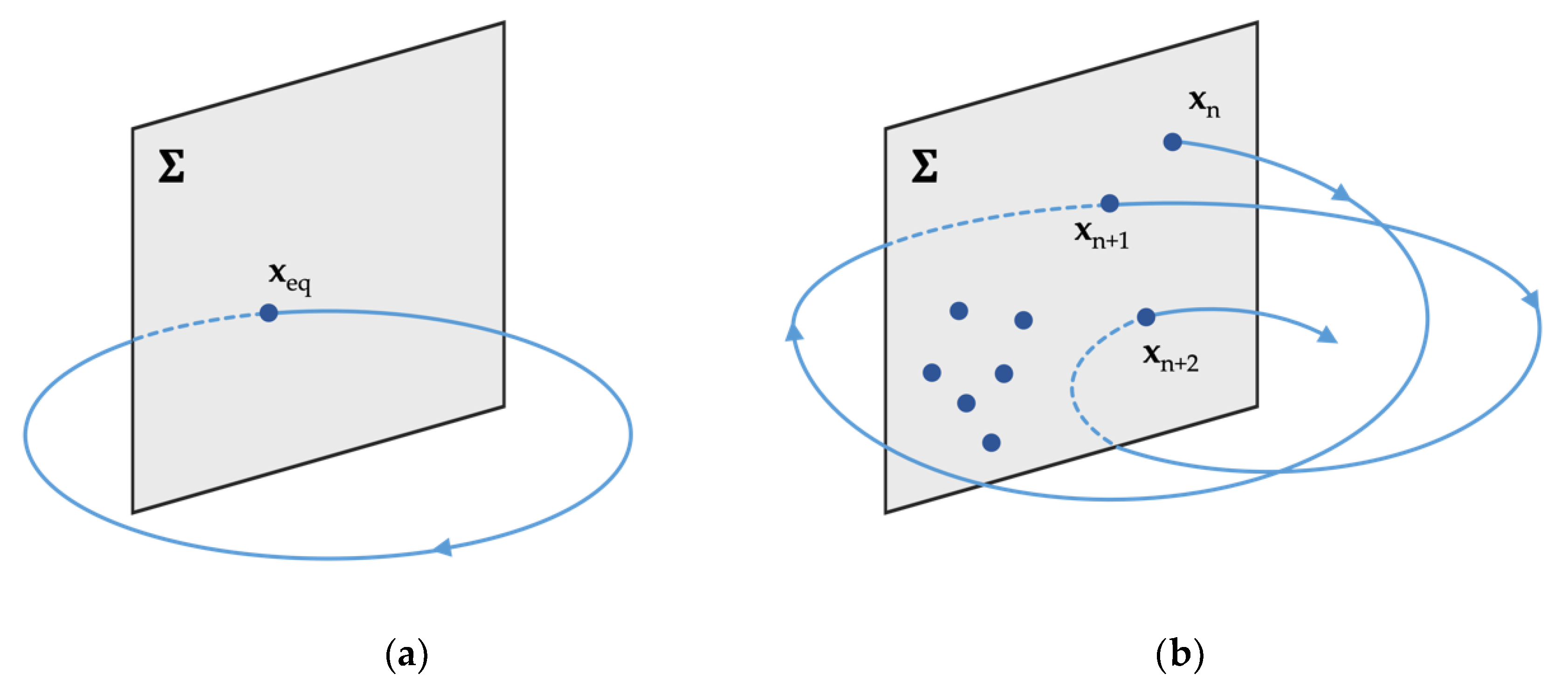
- Nayfeh, A.H.; Balachandran, B. Applied Nonlinear Dynamics: Analytical, Computational and Experimental Methods, 1st ed.; Wiley & Sons: New York, NY, USA, 1995; pp. 172–186. [Google Scholar]


| Parameter | Value | Unit | |
|---|---|---|---|
| Density of Asperities | (n) | 2.5 × 10¹⁰ | m−2 |
| Average Radius of Asperities | (β) | 10 × 10−6 | m |
| Slope of the Limiting Shear Stress-Pressure relation | (β0) | 0.047 | - |
| Standard Deviation of Asperities | (σs) | 0.2 × 10⁻⁶ | m |
| Limiting Shear Stress at Ambient Pressure | (τL0) | 2.5 × 10⁻⁶ | Pa |
| Viscosity (cSt) | |||||
|---|---|---|---|---|---|
| 40 °C | 100 °C | 55 °C (at Inlet) | Specific Gravity at 15 °C | Viscosity Index | |
| ISO-VG22 | 22 | 4.3 | 13.8 | 0.850 | 98 |
| Disc Parameter | Value | Unit | |
| Mass | (MJ/2) | 509.8 | kg |
| Amount of Imbalance on Disc * | (eimb) | 0.0‒0.2 Cb | - |
| Operation Speed Range * | - | 0‒25 | krpm |
| Bearing Parameter | Value | Unit | |
| Bearing Diameter | (D) | 100 | mm |
| Bearing Length * | (L) | 50, 75, 100 | mm |
| Bearing Clearance | (Cb) | 0.1 | mm |
| Bearing Load | (W) | 5 | kN |
| Lubricant Ambient Pressure | (Psup) | 0 | Pa |
| Lubricant Supply Pressure | (Pamb) | 0 | Pa |
| Pad Parameter | Value | Unit | |
| Number of Pads (arc Length) | - | 5 (60 deg, load on pad) | - |
| Preload * | (mp) | 1/2, 2/3, 3/4 | - |
| Offset * | (χp/χ) | 0.5, 0.55, 0.6 | - |
| Pad Clearance | (Cp) | 0.2 | mm |
| Pivot Radius * | (Rpvt) | 10, 15, 20 | mm |
© 2020 by the authors. Licensee MDPI, Basel, Switzerland. This article is an open access article distributed under the terms and conditions of the Creative Commons Attribution (CC BY) license (http://creativecommons.org/licenses/by/4.0/).
Share and Cite
Kim, S.; Byun, S.; Suh, J. Effects of Tilting Pad Journal Bearing Design Parameters on the Pad-Pivot Friction and Nonlinear Rotordynamic Bifurcations. Appl. Sci. 2020, 10, 5406. https://doi.org/10.3390/app10165406
Kim S, Byun S, Suh J. Effects of Tilting Pad Journal Bearing Design Parameters on the Pad-Pivot Friction and Nonlinear Rotordynamic Bifurcations. Applied Sciences. 2020; 10(16):5406. https://doi.org/10.3390/app10165406
Chicago/Turabian StyleKim, Sitae, Sangwon Byun, and Junho Suh. 2020. "Effects of Tilting Pad Journal Bearing Design Parameters on the Pad-Pivot Friction and Nonlinear Rotordynamic Bifurcations" Applied Sciences 10, no. 16: 5406. https://doi.org/10.3390/app10165406