Article

Bonding Behaviors of GFRP/Steel Bonded Joints after Wet–Dry Cyclic and Hygrothermal Curing

1
Key Laboratory of Concrete and Prestressed Concrete Structures, Ministry of Education, School of Civil Engineering, Southeast University, Nanjing 210096, China
2
Charles E. Via Jr. Department of Civil and Environmental Engineering, Virginia Polytechnic Institute and State University, Blacksburg, VA 24061, USA
3
School of Civil Engineering, Nanjing Forestry University, Nanjing 210037, China
*
Author to whom correspondence should be addressed.
Appl. Sci. 2020, 10(16), 5411; https://doi.org/10.3390/app10165411
Submission received: 10 July 2020 / Revised: 30 July 2020 / Accepted: 3 August 2020 / Published: 5 August 2020
(This article belongs to the Section Civil Engineering)

Abstract

:
This paper presents the outcomes of a research program that tested and examined the behaviors of glass fiber-reinforced polymer (GFRP) bonded steel double-strap joints after being cured in a variety of harsh curing conditions. Nineteen specimens were manufactured, cured in an air environment (the reference specimen), treated with different wet–dry cyclic curing or hygrothermal pretreatment, and then tested under quasi-static loading. Based on the experimental studies, mixed failure modes, rather than the cohesive failure of the adhesive, were found in the harsh environmental cured specimens. Additionally, an approximately linear relationship of load–displacement curves was observed for all the GFRP/steel bonded specimens from which the tensile capacities and stiffness were discussed. By analyzing the strain development of the bonded specimens during quasi-static tensile testing, the fracture mechanism analysis focused on the threshold value of the strain curves for different cured specimens. Finally, based on the studies of interfacial fracture energy, Gf, the effects of harsh environmental curing were assessed. The results showed that the failure modes, joint tensile capacities, stiffness, and interfacial fracture energy Gf were highly dependent on the curing conditions, and a significant degradation of bonding performance could be introduced by the investigated harsh environments.

1. Introduction

Subjected to various loading and working conditions, engineering structures showed different types of deterioration during their service life [1,2,3]. To mitigate such structural decreases, various repairing/retrofitting methods have been studied [4,5]. Among them, research on composite materials, especially, fiber-reinforced polymer (FRP), for steel structures has significantly increased during the past few decades [6,7,8,9], and the outstanding performance of FRP retrofitting/strengthening steel structures has been determined [6,10,11]. The most widely used composite materials are carbon fiber-reinforced polymer (CFRP) and glass fiber-reinforced polymer (GFRP). CFRP is commonly used where high elastic modulus is required [12]; even so, the much lower cost of GFRP is very important for a broader use of GFRP in engineering applications where low modulus of GFRP structures will not restrict the performance of composite systems, such as in steel–FRP hybrid bridges [13]. As a result, a lot of studies have been conducted on the behaviors of GFRP/steel strengthening systems [6,14,15].
The design and short-term mechanical behavior of GFRP/steel strengthening systems in constant environments have been researched and discussed extensively [10,16,17]. For engineering structures such as bridges, they are exposed to highly variable environments; for example, there are daily or seasonal changes in humidity and ambient temperature, which could affect the long-term behavior of adhesively bonded joints [18,19]. However, in-depth study on the long-term behaviors of the adhesively bonded joints considering moisture and thermal effect is still very limited.
To fill this research gap, this paper investigates the influence of different curing conditions on the mechanical behaviors of GFRP/steel bonded joints. Within this study, two series of curing program were introduced (wet–dry curing and hygrothermal pretreatment). The wet–dry curing experimental program included the characterization of cyclic moisture diffusion and thermal effects of the GFRP/steel bonded joints cured for different durations, whereas the hygrothermal pretreatment included different curing conditions of hygrothermal environments and durations. Based on the experimental study, the failure modes, tensile capacities, and strain curves were investigated, from which the interfacial fracture energy Gf of the bonded joints were calculated and discussed.

2. Experimental Program

2.1. Material Properties
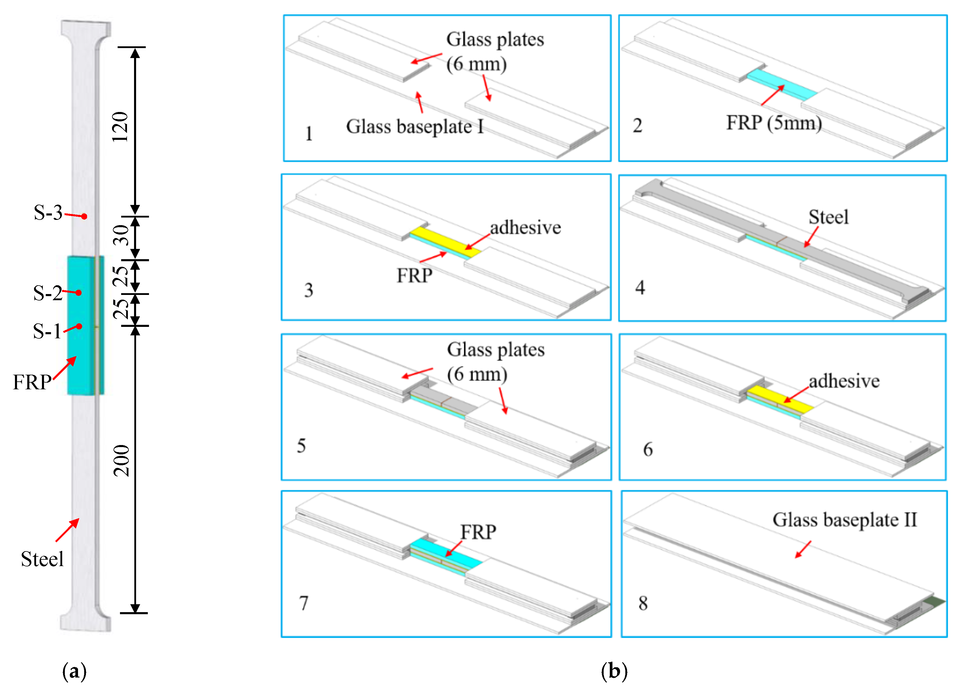
GFRP, methacrylate adhesives, and steel were the materials used in this study. The GFRP plates were fabricated through glass fibers and unsaturated polyester resin, and the pultrusion process was adopted. The tensile modulus and strength of the GFRP are listed in Table 1, which are obtained from the product tests by the Hengyi Company, Yangzhou, China. The methacrylate adhesive material was a super commercial two-part structural adhesive, PLEXUS MA 310 (with a fixture cure time of 55 min at 25 °C), and a specified operating temperature range from −55 to 121 °C. The Glass Transition Temperature (Tg) was 125 °C, which was tested and reported by Moller et al. [20]. The steel substrates were made of construction steel Q345b (similar to ASTM A572 Gr50). Based on tensile tests of steel coupons, the average yield strength and Young’s modulus of 291.3 MPa and 204.0 GPa were measured, respectively. It should be noted that the yield strength was much lower than the nominal value of 345 MPa; however, the present study focused on the behaviors of the bonding interfaces for the GFRP/steel specimens, and no failure of the steel substrates was found in the experiments. Therefore, it was concluded that the influence of the yield strength found in the steel substrates could be ignored. The mechanical properties of the materials in this experimental study are listed in Table 1.

2.2. Test Specimens

A total of 19 GFRP/steel bonded specimens were prepared; each specimen consisted of two GFRP plates and two steel substrates, as shown in Figure 1. The dimensions of the two GFRP plates were 100 mm × 20 mm × 5 mm, and the thickness and width of the steel substrates were 5 mm and 20 mm. To ensure a reliable bonding behavior, sandblasting was used as the surface preparation method before the bonding procedure. Before sandblasting, the substrates were cleaned twice with alcohol and then blasted with sand (first 800 grit, then 2000 grit) until a nonglossy surface was formed. Then, the surfaces were cleaned again with alcohol. Lastly, the GFRP was bonded on the substrates with methacrylate, and the thickness of the adhesive layers was formed to 1 mm; images of this bonding procedure are shown in Figure 1b. In addition, to measure the strains of the bonded joints during tensile tests, three strain gauges (S-1, S-2, and S-3) were bonded to the surface of each specimen, including two stain gauges (S-1 and S-2) on the surface of GFRP and another stain gauge (S-3) on the steel substrate. The dimensions of the specimens and locations of stain gauges are shown in Figure 1a.
Except for a reference specimen cured in an air environment (about 25 °C and 50% relative humidity) for three days, the bonded specimens were divided into two series: those cured under wet–dry cyclic conditions (WD) and those cured under hygrothermal conditions (HY). An environmental curing box that provides a variety of controlled environmental conditions, including moisture and thermal conditions, was used, as shown in Figure 2. In each cycle of the wet–dry (WD) curing, the specimens were placed in the environmental box for 12 h, which provided a fixed environment (e.g., 20 °C and 95% relative humidity), and then, they were put in a dry, room-temperature environment for another 12 h. Thirty-, 60-, and 90-day wet–dry curing cycles and three temperature levels (i.e., 20 °C, 40 °C, and 60 °C) were considered in this study. In the hygrothermal (HY) pretreatment curing, the specimens were placed in the environmental box for specific durations (i.e., 30-, 60-, and 90-day), and three temperature levels (i.e., 20 °C, 40 °C, and 60 °C) were considered. To ensure full solidification of the adhesives, the bonded specimens were cured for two hours at room temperature (about 25 °C with 50% relative humidity) before wet–dry cyclic curing or hygrothermal pretreatment. During the harsh curing period, the relative humidity in the environmental box was set at 95%. After harsh curing, the specimens were placed in a laboratory to air dry for three days.
The detailed description of the two series of specimens are shown in Table 2, where the testing specimens are labeled as [CC]-[D]-[T], where CC represents the categories of the curing condition, D is the duration of curing, and T is the temperature in the environmental curing box. For instance, WD-30-20 denotes the specimen that was cured with wet–dry cyclic condition for 30 days at 20 °C.

2.3. Quasi-Static Test

To investigate the bonding performance of the specimens after harsh curing, the bonded specimens were tested under quasi-static tensile load using a servo hydraulic test machine (MTS Landmark, with the maximum load capacity of 50 kN), as shown in Figure 3. The load was applied through the two ends of the specimen, with the displacement–control mode set at a rate of 1 mm/min. During the static tensile testing, the strains and axial displacement at both ends of the test specimens were recorded by the external electronic data acquisition system and by the sensors of the servo hydraulic test machine. The test results of the bonded joints are listed in Table 2. After tensile testing, the failure mode, or the interface fracture patterns of each specimen, were discussed.

3. Results and Discussion
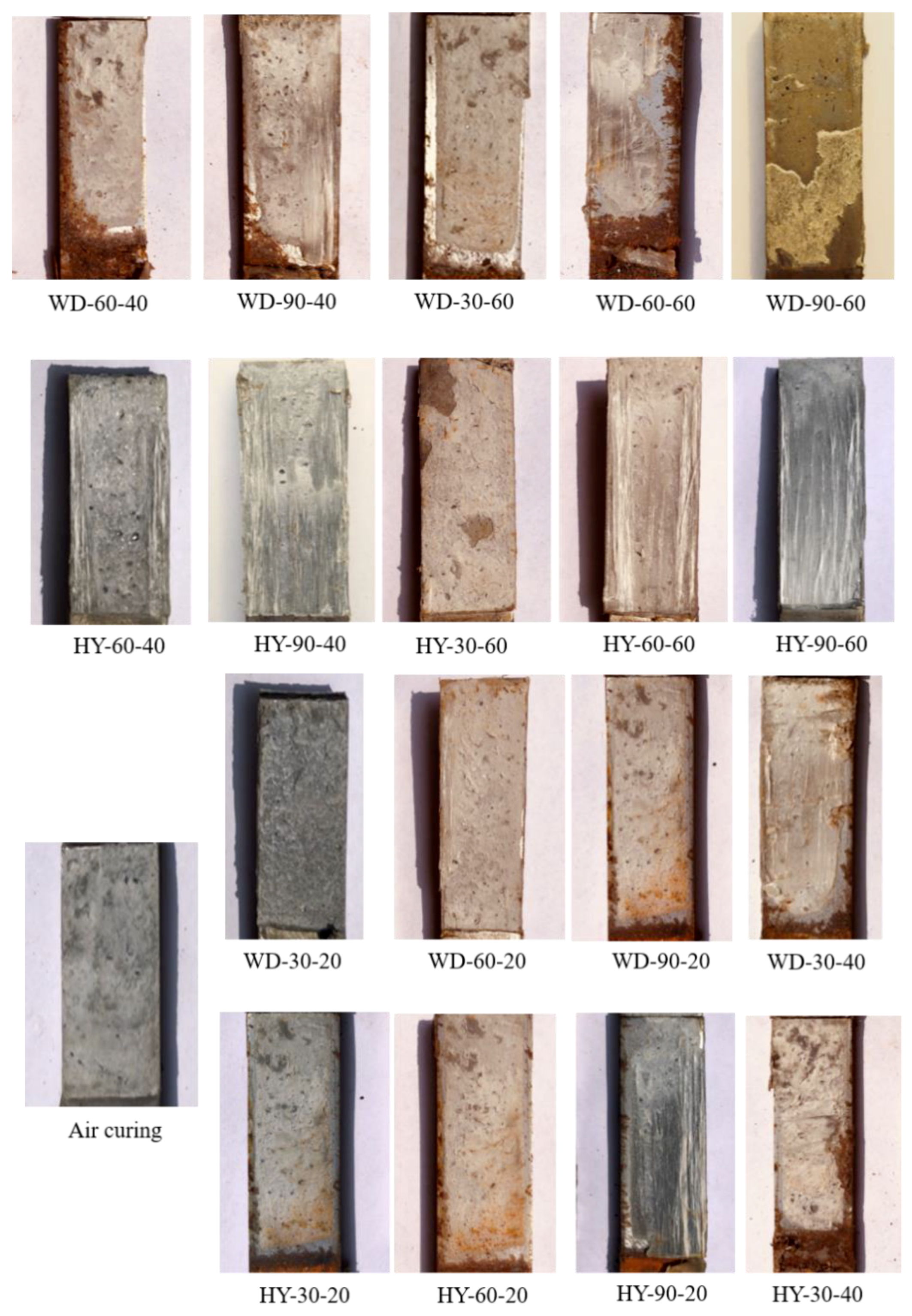
In this section, the results of quasi-static tensile tests of the 19 specimens with a variety of wet–dry or hygrothermal curing are presented and the testing results, failure modes, load–displacement (elongation) curves, strains of the specimens, interfacial fracture energy, and Gf, are discussed.

3.1. Failure Modes

Based on the test of reference specimens (i.e., the air curing specimen), a typical cohesive failure mode was observed, as shown in Figure 4a. In the cohesive failure, the fracture is inside the adhesive (i.e., the bonding material) rather than at the adhesive–structure interface, which means that the bond performance is desirable. Based on the record of the reference specimens during quasi-static tensile testing, it was observed that the fracture was initiated at the adhesive near the gap area of the specimen. As the load increased, cracking propagated toward the far end of the GFRP along the bonding layers and eventually resulted in complete disengagement of the GFRP plate from the steel substrates, indicating that the strength of the reference specimen highly depends on the properties of adhesive. The progressive propagation pattern of the bonding fracture for the reference specimen is shown in Figure 4b.
When compared with the reference specimen, several failure modes were observed for specimens subjected to wet–dry cyclic curing and hygrothermal pretreatment, as shown in Figure 5. For the series of WD specimens, in addition to a cohesive failure mode, mixed modes of cohesive failure and debonding of the adhesive–steel interfaces were found, especially in WD-90-60. It can be concluded that for the GFRP/steel joints subjected to the wet–dry cyclic curing, the degradation in the adhesive–GFRP interface and resin of GFRP may not be as serious as that in the adhesive–steel interface during the investigated duration. However, the delamination of GFRP was found in the series of HY specimens, especially in HY-90-40 and HY-90-60. This suggests that the interface between the adhesive and the steel substrates for the series of HY specimens, unlike the WD specimens, may not degrade as much as the adhesive and GFRP after being subjected to the hygrothermal pretreatment. Based on the phenomenon of failure modes for the bonded specimens, it was observed that the failure modes were affected significantly by curing conditions.

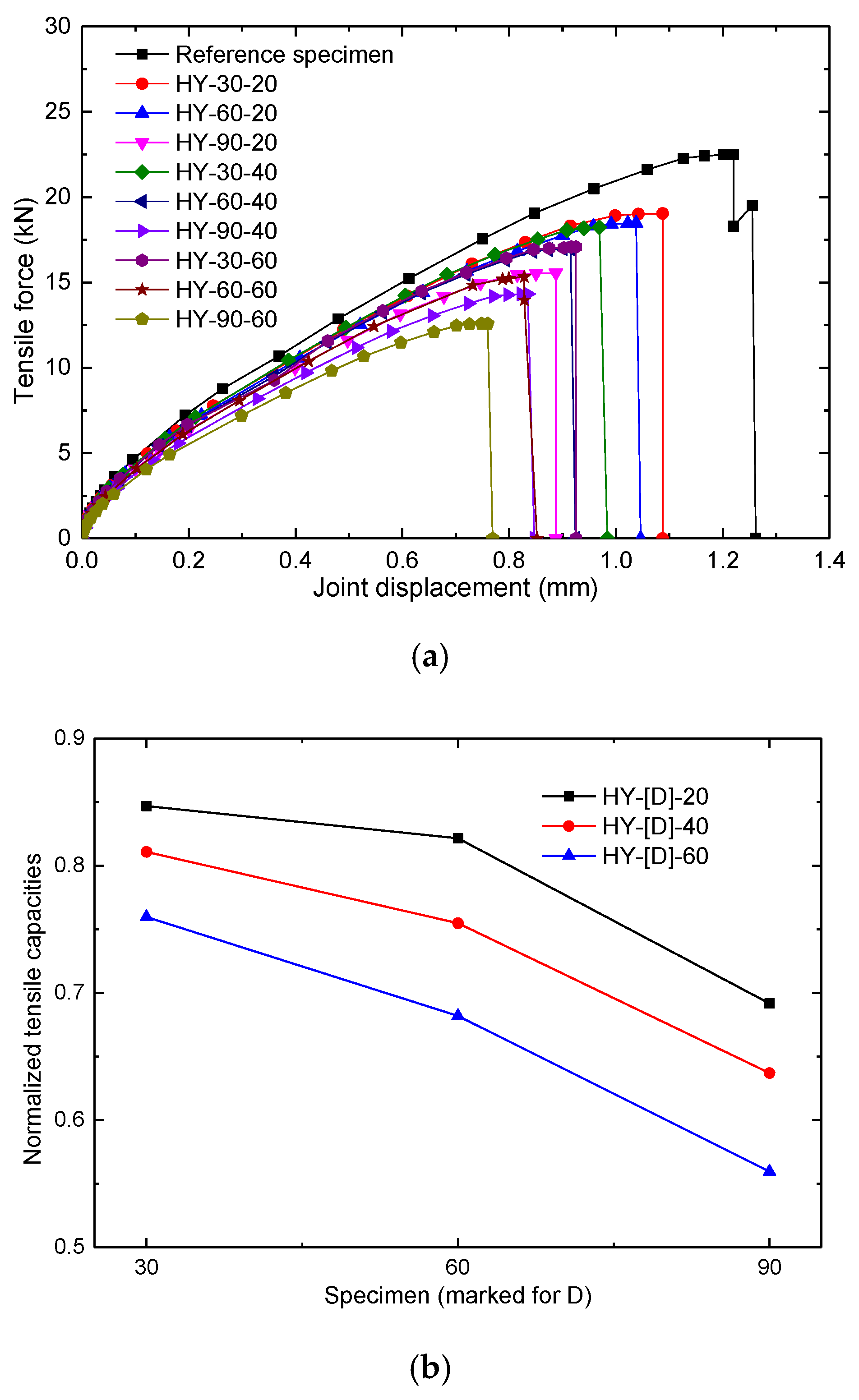
3.2. Load–Displacement Curves

Figure 6 shows the load versus joint displacement behaviors and normalized tensile capacities of the WD series bonded specimens. Based on the load–displacement curves in Figure 6a, approximately linear relationships of tensile load and displacement were found for all the specimens until they reached their tensile capacities, i.e., ultimate tensile loads. Once the ultimate tensile load was reached, the load was sharply reduced without increasing the joint displacement, corresponding to a brittle fracture of the bonded specimens. The tensile capacities and load–displacement curves are presented in Table 2 and Figure 6a. According to the debonding failure of the WD series in Figure 5, the tensile behaviors of the specimens of the WD series can be attributed to the premature debonding of the adhesive–steel interfaces that was caused by the degradation of wet–dry curing. Table 2 shows that when compared with the reference specimen (22.48 kN), a significant reduction of tensile capacities occurred for the specimens exposed to wet–dry cyclic curing, especially for the specimen WD-90-60 (10.26 kN). This phenomenon may be attributed to the moisture diffusion and heat transfer mechanisms in the cured specimens [21].
The tensile capacity of each joint of the WD series under different curing conditions was normalized by that of the specimen cured in the air environment (i.e., the reference specimen), as shown in Figure 6b. By comparing the results of WD-[D]-20 (i.e., WD-30-20, WD-60-20, and WD-90-20), the lowest tensile capacity was found in the specimen cured the longest (WD-90-20), indicating that a more severe degradation of bonding performance (i.e., interfacial and adhesive properties) was introduced by a longer wet–dry cyclic curing duration. A similar phenomenon was observed in the series of WD-[D]-40 and WD-[D]-60. For WD-30-[T] (i.e., WD-30-20, WD-30-40, and WD-30-20) with the same wet–dry duration under different temperatures, a lower tensile capacity was found with a higher curing temperature. Therefore, the adhesive–steel interface and adhesive may deteriorate at a high temperature. The smallest normalized tensile capacity, 46%, was observed in specimen WD-90-60, which was cured for 90 days (wet–dry) at 60 °C, showing the combined negative effect introduced by longer curing time curing and higher temperature.
For HY series testing, a similar reduction of tensile capacity was observed in Figure 7, which shows that the degradation of the bonded joints could be caused by the hygrothermal pretreatment. However, according to the delamination failure of GFRP in HY series testing (as shown in Figure 4), the GFRP material properties could degrade after the hygrothermal pretreatment, and the degradation would become more severe with longer exposure durations and higher curing temperature.

3.3. Stiffness Analysis

To investigate the stiffness of the specimens cured with different harsh environments (i.e., wet–dry cyclic curing and hygrothermal pretreatment), the elongation at the break was examined. For this study, the specimens had highly different tensile capacities and ultimate elongations after being cured in different environments. Rather than analyzing the ultimate tensile strength and displacement directly, displacements under a fixed load, i.e., 10 kN (as shown in Figure 8), are discussed in this section. It is found that displacements of specimens cured in a harsh environment are larger than that of the reference specimen (cured in an air environment). Furthermore, the longer exposure to the harsh environment resulted in the larger measured displacement. The largest displacement was measured in WD-90-60 (being 0.63 mm), indicating that the stiffness of joints may be reduced by wet–dry cyclic curing and hygrothermal pretreatment, especially when cured with a longer exposure duration and higher temperature.

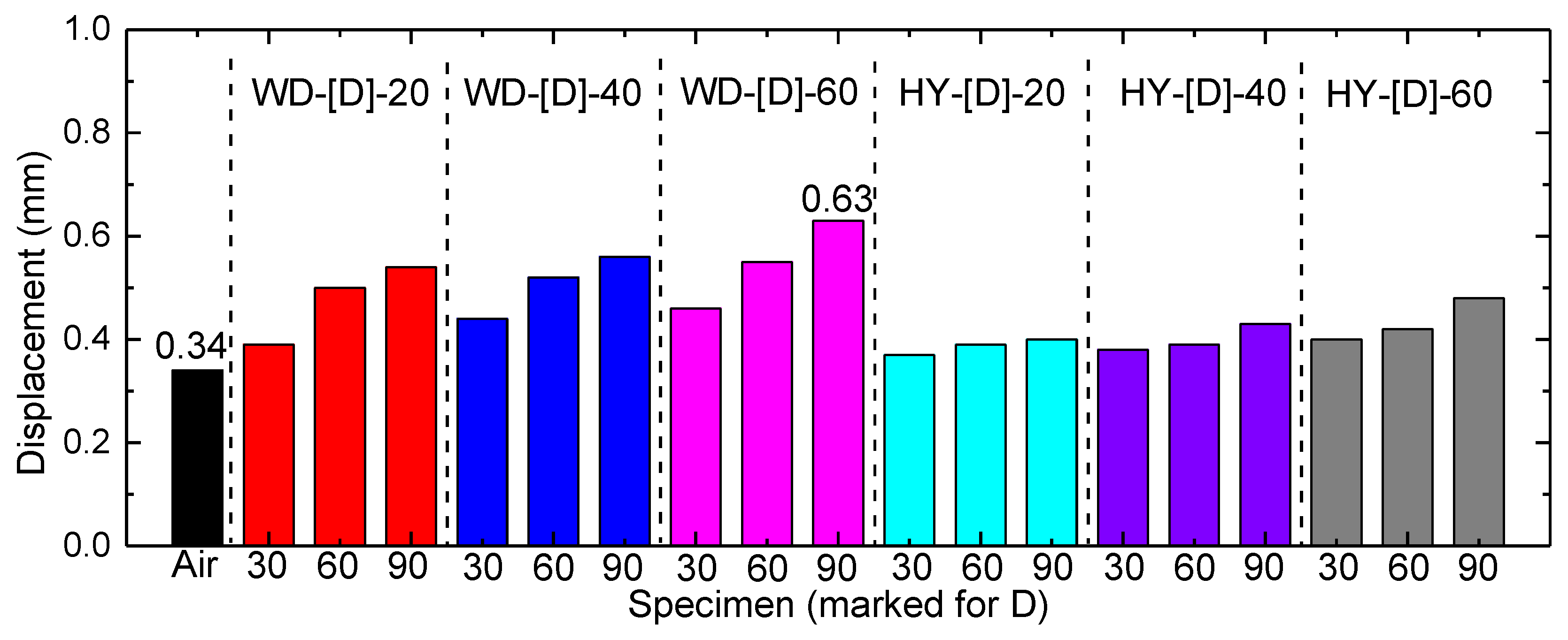
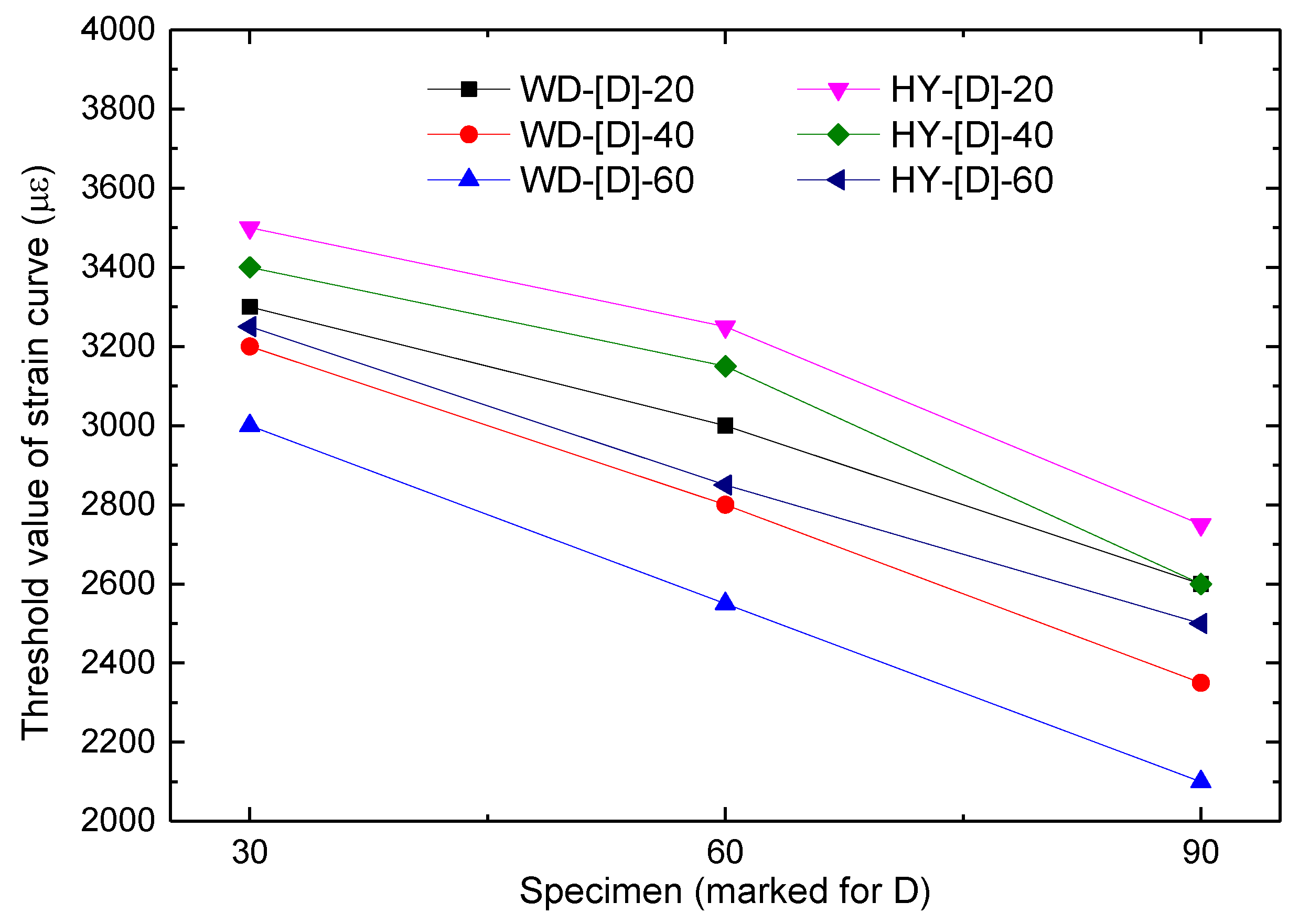
3.4. Strain Development During Quasi-Static Tensile Tests

To investigate the distribution and development of the stress/strain relationship of the testing specimens, the strain data were obtained from the data recorded during the data acquisition system testing. The locations of strain gauges are shown in Figure 1. Figure 9 shows the strain development during some quasi-static tensile tests (Reference, WD-90-60 and HY-90-60 specimens), and the other specimens had similar results. It can be observed that the absolute strains of the specimens increased when the tensile forces increased until the ultimate tensile capacities were achieved. When the ultimate tensile displacements (i.e., elongation of the joints) were reached, the strains were reduced significantly, which is similar to the load–displacement curves in Figure 6.
A two-stage strain development was found for S-1 and S-2. In stage I (beginning of testing), strains increase relatively moderately, until reaching a certain threshold (for instance, approximate threshold as 3700 με for S-1 of reference specimen), where strains become unstable and quickly increase, leading to failure of the specimen. The following observations were made when each strain history was compared.
(1)
For strains measured by the gauge S-1, the strain increase accelerated after the strain exceeded a certain threshold, indicating a progressive degradation of GFRP materials when the tensile load was increased and the load was transferred to the outer surfaces of GFRP. While the reference test had a larger tensile capacity, the accelerating strain growth of the S-1 gauge indicated that the GFRP was weakened when the load exceeded a certain threshold. However, for WD-90-60 and HY-90-60 testing, compared with the reference specimen, a premature accelerating increase of S-1 was observed, showing the effect of the harsh environment on the GFRP materials. According to Figure 9b,c, thresholds of accelerating growth of about 2100 and 2500 με could be determined for WD-90-60 and HY-90-60, respectively, which are much smaller than the reference specimen (about 3700 με), indicating that the moisture diffusion combined with heat effect may negatively affect the GFRP materials, and the threshold value of degradation for GFRP has been reduced.
(2)
For strains measured by gauge S-2, the similar two-stage accelerating growth was found as the displacement/loading increased, which could be attributed to the debonding failure, including the cohesive failure of adhesive, delamination in the GFRP, debonding at the adhesive–steel interface, and shifting of the load-transferring area to the bonding ends.
(3)
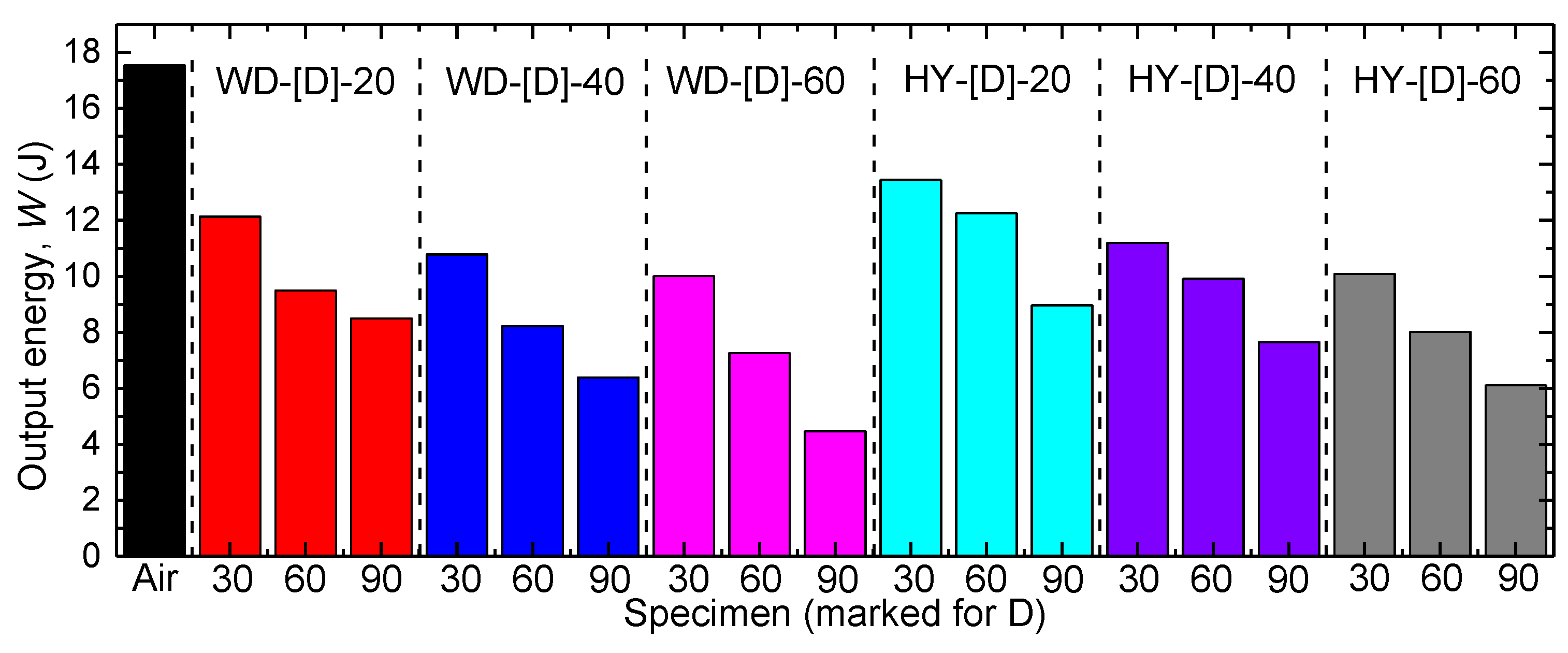
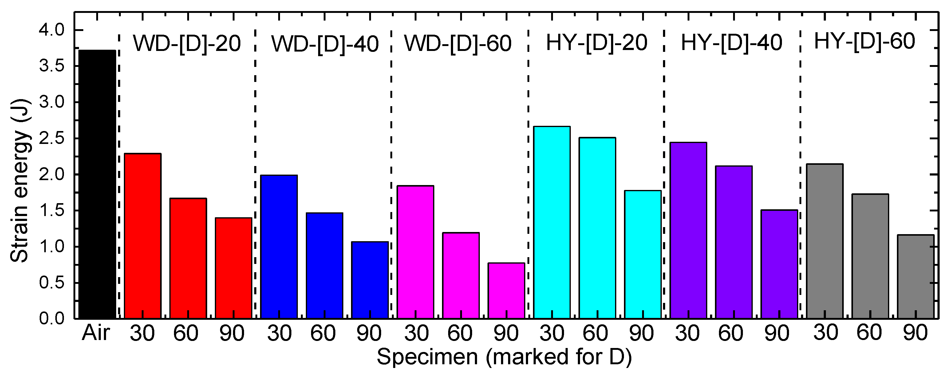
The development of strains measured by gauge S-3 showed the same shape as the load–displacement curves seen in Figure 6 and Figure 7, indicating the linear elastic behavior of the steel substrates during tensile testing (with no larger than 225 MPa for all testing specimens, far less than the yield strength of the steel substrates). The strain data of gauge S-3 were adopted to calculate the strain energy during tensile testing in the discussion of interfacial fracture energy.
In order to investigate the degradation of the GFRP materials for the bonded specimens cured in the other conditions, the variation of threshold values of the S-1 curves was adopted and is shown in Figure 10. By comparing the threshold value of S-1 curves of the specimens cured in harsh environments, it was observed that all the threshold values of specimens cured in harsh environment were smaller than the reference specimen (3700 με), indicating the negative effect of the investigated harsh curing conditions on the GFRP composites [21]. Moreover, by comparing the specimens cured under the same temperature, a lower threshold value could be adopted by specimens cured with longer duration, such as specimens of series WD-[D]-20, where the threshold value changes from 3300 με (WD-30-20) to 2600 με (WD-90-20), indicating the increasingly negative influence of the longer harsh curing. Moreover, for the WD-30-[T] (i.e., WD-30-20, WD-30-40, and WD-30-20) with the same curing duration under different temperatures, the threshold value changes from 3300 με (WD-30-20) to 3000 με (WD-30-60), indicating that the higher curing temperature results in the lower threshold value.

4. Interfacial Fracture Energy

In the context of studies on FRP-to-concrete and FRP-to-steel bonded joints, the interfacial fracture energy, Gf, is one of the most important indices to express the bonding behaviors [22]. However, in this study, the strength of the adhesive, GFRP materials, and interfacial strength decreased continuously with an increase in harsh curing duration, by which the failure mode of the specimens, after harsh aging transferred from a cohesive failure to an adhesive–steel interface debonding (for wet–dry cyclic curing) or delamination of GFRP (for hygrothermal pretreatment). Different failure modes may affect the interfacial fracture energy Gf, and therefore, it is inappropriate to calculate the interfacial fracture energy Gf through traditional methods.
The output energy of the loading machine during quasi-static tensile testing is equal to the sum of three sources of energy: strain energy in the steel substrates, thermal energy, and energy in the bonding part. Assuming that the thermal effect was negligible, the energy in the bonded part, which could be regarded as the interfacial fracture energy (Gf) in this study, can be calculated by following equation:
G b = W G s
where Gb is the energy stored in the bonded part before fracture occurred, W is the total output energy of the loading machine, and Gs is the strain energy of the steel substrate. W was calculated by measuring the area underneath the load–displacement curves, which is shown in Figure 11.
The strain energy in steel substrates was calculated by assuming a pure elastic tensile deformation of the steel substrates during the quasi-static tensile loading, and the elastic energy in steel substrates was calculated by Equations (2) and (3), as follows:
G s = 1 2 ε 2 E s V
V = l × A
where Gs is the strain energy of the steel substrate, ε is the strain of the steel substrate (S-3), Es is the Young’s Modulus of the steel material, and V is the volume of the steel substrate. In addition, the parameters l and A are the length and area of the steel substrate, which were 300 mm (2 × 150 mm = 300 mm) and 100 mm2 (5 mm × 20 mm = 100 mm2), respectively. The calculated strain energy of the steel substrates for each specimen before failure occurred is shown in Figure 12.
Based on the fracture mechanism of the bonding specimens during quasi-static tensile loading, the interfacial fracture energy of the specimens could be calculated through Gb by using Equation (1), as shown in Figure 13. Compared with the reference specimen, specimens cured in harsh environmental conditions showed a significant reduction in interfacial fracture energy, indicating the undesirable effect of the harsh environmental curing on the bond behavior. Figure 14 shows the normalized interfacial fracture energies of specimens cured in different conditions.
According to Figure 13 and Figure 14, by comparing the results of WD-[D]-20 (i.e., WD-30-20, WD-60-20, and WD-90-20) with the same curing temperature, lower interfacial fracture energy was observed for the specimen with longer curing, indicating that a more severe reduction of interfacial fracture energy could be introduced by longer wet–dry cyclic curing duration. Similar observations were found in test series of WD-[D]-40, WD-[D]-60, and HY-[D]-[T]. For WD-30-[T] (i.e., WD-30-20, WD-30-40, and WD-30-60) with the same wet–dry duration and different temperatures, the interfacial fracture energy Gb was reduced from 9.84 J (WD-30-20) to 8.17 J (WD-30-60), showing the negative effect of higher temperature. A similar degradation of interfacial fracture energy was found in HY series testing.

5. Conclusions

This paper examined the bond behaviors of GFRP/steel double-strap joints after harsh environmental curing (wet–dry cyclic curing and hygrothermal pretreatment). Experimental studies were carried out by quasi-static loading, and failure mode, ultimate load, stiffness, strain development, and interfacial fracture energy were discussed. Based on the experimental results, the following conclusions were made:
(1)
In addition to the cohesive failure mode of the reference specimen, mixed modes of cohesive failure and debonding of the adhesive–steel interface were found in the WD series specimens. Additionally, mixed failure modes of cohesive failure and the delamination of GFRP composites were found in HY series specimens. The changes of failure mode indicate that the bonding performance of the GFRP/steel bonded specimens are affected by curing conditions under moisture diffusion and thermal effects.
(2)
Linear brittle behavior was observed for all of the bonded specimens. Based on the investigation on the ultimate load of the specimens, a significant reduction of tensile capacities was observed for specimens cured in harsh environments, especially for longer exposure duration and higher curing temperature. Further investigation on stiffness of the bonded joints shows that the stiffness was reduced by curing in the harsh environments.
(3)
A two-stage strain development was found for all bonded specimens, and the threshold stain values are the key parameter to qualify the failure process. As compared with the reference specimen, the harsh cured specimens had smaller threshold stain values, indicating the negative effect of moisture diffusion and heat transfer.
(4)
A method to calculate the interfacial fracture energy of the bonded specimens is proposed. According to the calculation and comparison, a more severe reduction in interfacial fracture energy could be caused by longer curing and higher curing temperatures.

Data Availability Statement

The data used to support the findings of this study are available from the corresponding author upon request.

Author Contributions

Conceptualization, J.L.; Data curation, J.L.; Funding acquisition, T.G.; Investigation, J.L.; Methodology, J.L., T.G. and M.H.H.; Project administration, M.H.H.; Resources, T.G.; Supervision, T.G.; Validation, L.W.; Visualization, Z.L.; Writing—original draft, J.L.; Writing—review and editing, T.G. All authors have read and agreed to the published version of the manuscript.

Funding

This work was supported by the National Science Foundation of China [Grant Number: 51978156] and the Scientific Research Foundation of the Graduate School of Southeast University [Grant Number: YBJJ1551].

Conflicts of Interest

The authors declare that they have no known competing financial interests or personal relationships that could have appeared to influence the work reported in this paper.

References

  1. Guo, T.; Liu, Z.; Correia, J.; de Jesus, A.M. Experimental study on fretting-fatigue of bridge cable wires. Int. J. Fatigue 2020, 131, 105321. [Google Scholar] [CrossRef]
  2. Guo, T.; Frangopol, D.M.; Chen, Y. Fatigue reliability assessment of steel bridge details integrating weigh-in-motion data and probabilistic finite element analysis. Comput. Struct. 2012, 112, 245–257. [Google Scholar] [CrossRef]
  3. Kaloop, M.R.; Jong, W.H.; Yasser, B. Identification of the response of a controlled building structure subjected to seismic load by using nonlinear system models. Appl. Sci. 2016, 6, 301. [Google Scholar] [CrossRef] [Green Version]
  4. Park, H.-C.; Lee, C.-H.; Chang, K.-H. Strengthening a damaged steel girder bridge by the replacement repair welding. KSCE J. Civ. Eng. 2012, 16, 1243–1249. [Google Scholar] [CrossRef]
  5. Fu, Z.; Ji, B.; Kong, X.; Chen, X. Grinding treatment effect on rib-to-roof weld fatigue performance of steel bridge decks. J. Constr. Steel Res. 2017, 129, 163–170. [Google Scholar] [CrossRef]
  6. Liu, J.; Guo, T.; Feng, D.; Liu, Z. Fatigue Performance of Rib-to-Deck Joints Strengthened with FRP Angles. J. Bridge Eng. 2018, 23, 04018060. [Google Scholar] [CrossRef]
  7. Guo, T.; Liu, J.; Deng, Y.; Zhang, Z. Fatigue Performance of Orthotropic Steel Decks with FRP Angles: Field Measurement and Numerical Analysis. J. Perform. Constr. Facil. 2019, 33, 04019042. [Google Scholar] [CrossRef]
  8. Lavorato, D.; Camillo, N.; Silvia, S. Experimental investigation of the shear strength of RC beams extracted from an old structure and strengthened by carbon FRP U-strips. Appl. Sci. 2018, 8, 1182. [Google Scholar] [CrossRef] [Green Version]
  9. Mansouri, I.; Jong, W.H.; Ozgur, K. Novel predictive model of the debonding strength for masonry members retrofitted with FRP. Appl. Sci. 2016, 6, 337. [Google Scholar] [CrossRef]
  10. Hosseini, A.; Ghafoori, E.; Wellauer, M.; Marzaleh, A.S.; Motavalli, M. Short-term bond behavior and debonding capacity of prestressed CFRP composites to steel substrate. Eng. Struct. 2018, 176, 935–947. [Google Scholar] [CrossRef]
  11. Zhang, D.; Shi, H.; Zhu, J.; Su, M.; Jin, W.L. Cover separation of CFRP strengthened beam-type cantilevers with steel bolt anchorage. Eng. Struct. 2018, 156, 224–234. [Google Scholar] [CrossRef] [Green Version]
  12. Askandar, N.; Mahmood, A. Comparative Investigation on Torsional Behaviour of RC Beam Strengthened with CFRP Fabric Wrapping and Near-Surface Mounted (NSM) Steel Bar. Adv. Civ. Eng. 2019, 2019. [Google Scholar] [CrossRef]
  13. Mara, V.; Haghani, R.; Harryson, P. Bridge decks of fibre reinforced polymer (FRP): A sustainable solution. Constr. Build. Mater. 2014, 50, 190–199. [Google Scholar] [CrossRef] [Green Version]
  14. Keller, T.; Rothe, J.; De Castro, J.; Osei-Antwi, M. GFRP-balsa sandwich bridge deck: Concept, design, and experimental validation. J. Compos. Constr. 2013, 18, 04013043. [Google Scholar] [CrossRef]
  15. Satasivam, S.; Bai, Y.; Yang, Y.; Zhu, L.; Zhao, X.L. Mechanical performance of two-way modular FRP sandwich slabs. Compos. Struct. 2018, 184, 904–916. [Google Scholar] [CrossRef]
  16. Bocciarelli, M.; Colombi, P.; Fava, G.; Sonzogni, L. Energy-based analytical formulation for the prediction of end debonding in strengthened steel beams. Compos. Struct. 2016, 153, 212–221. [Google Scholar] [CrossRef]
  17. Haghani, R.; Al-Emrani, M. A new design model for adhesive joints used to bond FRP laminates to steel beams–Part A: Background and theory. Constr. Build. Mater. 2012, 34, 486–493. [Google Scholar] [CrossRef]
  18. Heshmati, M.; Haghani, R.; Al-Emrani, M. Effects of moisture on the long-term performance of adhesively bonded FRP/steel joints used in bridges. Compos. Part B Eng. 2016, 92, 447–462. [Google Scholar] [CrossRef]
  19. Nguyen, T.C.; Bai, Y.; Zhao, X.L.; Al-Mahaidi, R. Durability of steel/CFRP double strap joints exposed to sea water, cyclic temperature and humidity. Compos. Struct. 2012, 94, 1834–1845. [Google Scholar] [CrossRef]
  20. Moller, J.; Hunter, R.; Molina, J.; Vizán, A.; Peréz, J.; da Silva, L.F.M. Influence of the temperature on the fracture energy of a methacrylate adhesive for mining applications. Appl. Adhes. Sci. 2015, 3, 14. [Google Scholar] [CrossRef] [Green Version]
  21. Heshmati, M.; Haghani, R.; Al-Emrani, M. Environmental durability of adhesively bonded FRP/steel joints in civil engineering applications: State of the art. Compos. Part B Eng. 2015, 81, 259–275. [Google Scholar] [CrossRef]
  22. Liang, H.; Li, S.; Lu, Y.; Yang, T. Reliability analysis of bond behaviour of CFRP—Concrete interface under wet—Dry cycles. Materials 2018, 11, 741. [Google Scholar] [CrossRef] [PubMed] [Green Version]
Figure 1. Dimensions of bonded specimen and bonding process (unit: mm). (a) Specimen; (b) Bonding Process.
Applsci 10 05411 g001
Figure 2. Environmental curing box.
Applsci 10 05411 g002
Figure 3. Quasi-static test setup.
Applsci 10 05411 g003
Figure 4. Failure surface and cracking propagation of the reference specimen. (a) Failure Surface; (b) Cracking Propagation.
Applsci 10 05411 g004
Figure 5. Photographs of the failure surfaces.
Applsci 10 05411 g005
Figure 6. Specimens of wet–dry (WD) series. (a) Load–Displacement Curves; (b) Normalized Tensile Capacities.
Applsci 10 05411 g006
Figure 7. Specimens of hygrothermal conditions (HY) series. (a) Load–Displacement Curves; (b) Normalized Tensile Capacities.
Applsci 10 05411 g007
Figure 8. Displacements of each specimen under 10 kN.
Applsci 10 05411 g008
Figure 9. Strain development during quasi-static tensile tests. (a) Reference specimen; (b) WD-90-60; (c) HY-90-60.
Applsci 10 05411 g009aApplsci 10 05411 g009b
Figure 10. Threshold values of strain curves.
Applsci 10 05411 g010
Figure 11. Output energy of loading machine before fracture occurred.
Applsci 10 05411 g011
Figure 12. Strain energy of steel substrates before fracture occurred.
Applsci 10 05411 g012
Figure 13. Interfacial fracture energy of the test specimens.
Applsci 10 05411 g013
Figure 14. Normalized interfacial fracture energies of the cured specimens.
Applsci 10 05411 g014
Table 1. Mechanical properties of glass fiber-reinforced polymer (GFRP), adhesive, and steel.
Mechanical ParameterGFRPAdhesiveSteel
Young’s Modulus, MPa15,400 (longitudinal direction)1034–1207204,000
6850 (transverse direction)
7630 (thickness direction)
Strength, MPa291.1 (longitudinal direction)24.1–31.0291.3 (Yield stress)
125.3 (transverse direction)
144.6 (thickness direction)
Poisson’s ratio0.370.400.30
Table 2. Summary of the specimens.
Specimen CategoriesCuring Time n (Days)Temperature (°C)Tensile Capacity (kN)Elongation (mm)
Reference0Air22.481.262
WD-30-20302017.641.058
WD-60-20602015.061.006
WD-90-20902013.790.974
WD-30-40304016.451.035
WD-60-40604014.131.001
WD-90-40904012.050.840
WD-30-60306015.830.998
WD-60-60606012.740.899
WD-90-60906010.260.693
HY-30-20302019.041.087
HY-60-20602018.471.038
HY-90-20902015.550.887
HY-30-40304018.230.984
HY-60-40604016.970.924
HY-90-40904014.320.847
HY-30-60306017.080.925
HY-60-60606015.330.852
HY-90-60906012.580.769
Note: Tensile strength and elongation will be discussed in detail later.

