Featured Application
The results in this article show good application prospects for a transonic axial compressor/fan with a tandem blade. In addition, the results in this paper show an innovative way to improve the transonic tandem blade performance.
Abstract
Tandem blade technology has become an effective method to break the load limit of conventional aerodynamic configurations. To expand the application range of tandem blades, the supersonic tandem blade flow characteristic was studied and an optimal design was conducted by using a computational fluid dynamics (CFD) solver, with an inflow Mach number of 1.2. The main conclusions follow: (1) the tandem blade loss is difficult to control because of the complicated flow structures with supersonic inflow; (2) the forward blade loss dominates the tandem blade overall loss in the whole operating conditions; and (3) the tandem blade profile was optimized by considering the aerodynamic interaction between forward and aft blade. The numerical simulation results show that the total pressure loss declines by 20% at the design point, and the incidence range increases by about 0.5°.
1. Introduction
Increasing the aerodynamic loading of the compressor is of great significance for shortening the axial length of the aero-engine and reducing the weight of the structure. Therefore, the question, how to improve the compressor loading, has been a hot issue in the field of aerodynamic design [1]. Under such background, the tandem blade technology has become an effective method to break the load limit of conventional aerodynamic configurations, and it is of wide interest by researchers.
Earlier studies of a tandem blade showed the potential performance advantages, especially in aerodynamic loaded conditions. In the 1970s, the Pratt and Whitney Group conducted a systematic investigation for highly loaded tandem blades using a single-stage test rig [2,3]. Comparisons of conventional and tandem blade experiment results indicated that a tandem blade achieved better performance in pressure ratio and efficiency. Bammert et al. [4,5] designed and optimized the tandem blades in a multistage axial compressor, and the flow loss decreased about 18 percent relative to the conventional configuration. By 1990, Wennerstrom [6] summarized the different technology roadmaps for highly loaded axial flow compressors, and pointed out the loaded capacity of the tandem blade.
The tandem blade can be regarded as a special configuration split out from the conventional blade, and thus more degrees of freedom in blade design and optimization have to be considered. Therefore, a large number of investigations were conducted for exploring the influence of new design variables on tandem blade performance. The key design principles were extracted after many theoretical analyses, numerical simulations, and cascade experiments. Nezym et al. [7] established the mathematical model of tandem airfoil loss based on a large number of experimental results, and systematically studied how these key parameters (such as the relative position, the solidity ratio, and the camber ratio of front and rear blade) affect the blade performance. McGlumphy et al. [8] investigated the relative position of the 2D tandem blade (explained in Figure 1) under the subsonic condition, and they pointed out that the tandem blade achieves the best performance when the AO is approximately zero and the PP is close to 0.7~0.8. The study of Hoeger et al. [9,10] showed a transonic tandem blade with a large overlap achieved a loss reduction of 30 percent and increase of turning of 10 percent. Baojie Liu [11] presented a model to predict the minimum-loss incidence and deviation angles of a splitter blade, and it pointed out a way to guide the splitter blade into conventional design processes. Their efforts provide a reference to develop the empirical model for tandem blade design. Furthermore, the mathematical model [12,13] used for the analysis of entropy generation and heat transfer [14] also can be referenced to estimate tandem blade performance.
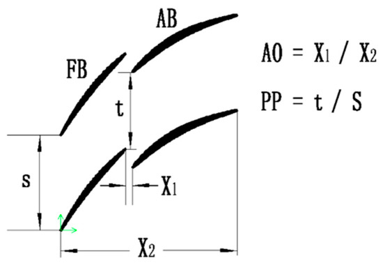
Figure 1.
Sketch map of a tandem blade.
The CFD (computational fluid dynamics) combined numerical optimization algorithm rising in recent years has been adapted for tandem blade design. The numerical optimization method can help designers find the optimal solution, and even carry out in-depth analysis to further understand the flow mechanism. Schlaps et al. [15] optimized the 3D tandem stator relative position with the multiobjective algorithm, and the optimal relative position principle was summarized. Ju et al. [16] optimized a 2D tandem blade with the multiobjective genetic algorithm and artificial neural network method. A massive amount of simulation results [17,18,19,20] indicated that the tandem blade performance should be estimated in design and off-design conditions comprehensively; for instance, a larger pitchwise blade distance will lead to an increase of the loss and the choke margin simultaneously. All the results stated above show the prescribed velocity distribution design concept has become an effective measure in highly loaded axial compressors optimization.
As stated above, the tandem blade behavior in subsonic flow has been investigated systematically. To our best knowledge, little effort has been devoted to the tandem blade with a supersonic inflow, especially the design principles for complicated shock structures, which limit the application range of tandem blade, especially for a transonic tandem rotor. In addition, the most commonly used airfoils in tandem blade are based on the combination with tow conventional blades (such as NACA65, double circular airfoil, controlled diffusion airfoil). This is a simple and practical pattern in subsonic inflow, but circumstances are different in supersonic inflow; the shock wave structure in the front and aft blade channel is strong and complicated, which will change the ideal pressure distribution of the conventional blades. Furthermore, the blade performance (total pressure loss coefficient, incidence range, etc.) is highly sensitive to geometric changes, which puts forward stricter requirements for flow control in tandem blade.
Based on the discussion above, this paper tries to reveal the flow characteristic and conducts an optimal design in supersonic tandem blade with an inflow Mach number of 1.2, which is the typical value of a transonic tandem rotor tip. It is mainly carried out from the following two aspects: firstly, the flow mechanism in tandem blade was studied with an inflow Mach number of 1.2; secondly, the supersonic tandem blade was optimized on the condition that considers the aerodynamic interaction between a forward and aft blade.
2. Numerical Simulation Method
2.1. Geometric and Aerodynamic Parameters
Table 1 gives the meanings of abbreviations used in tandem blade description. Aerodynamic evaluation parameters of the tandem blade studied in this paper are shown in Table 2.

Table 1.
Nomenclature and abbreviations.
Table 2.
Aerodynamic evaluation parameters.
2.2. Geometric Model Setup
The numerical simulations were based on a 2D blade-to-blade section derived from a transonic tandem rotor tip (90% blade height), including the baseline airfoil and boundary condition. Due to the limitations of strength factors (e.g., aspect ratio, tip/hub chord length ratio, and the compound sweep/curve quantities of the rotor), the range selection of tandem blade design parameters (e.g., AO/PP, solidity ratio) was constrained. Therefore, design parameters shown in Table 3 could not be selected within the optimal selection interval recognized by previous experience.
Table 3.
Tandem blade geometric parameters.
2.3. Computational Grid
In blade-to-blade surface, a structured mesh was generated by using the AutoGrid5 software package. For the tandem configuration, each blade passage was meshed individually and matched to the other passage’s mesh with a special algorithm, as shown in Figure 2. The total number of grids was about 530,000 (the number of axial, circumferential, and spanwise grids: 438 × 71 × 17), in which 97 grids were arranged along the flow direction in forward blade (FB) and aft blade (AB). The first nondimensional wall distance was specified to ensure y + less than 5, and the grid expansion ratio from the boundary layer to the mainstream was less than 1.2. Six cases with a different number of grids were investigated to increase the accuracy of the simulation results, which are shown in Table 4. The blade performance tends to be stable when the number of grids is greater than 470,000. Considering the convergence speed and calculation accuracy, Case 4 was used as the CFD mesh for further analysis.
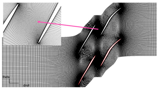
Figure 2.
Tandem blade CFD (computational fluid dynamics) mesh.
Table 4.
The aerodynamic parameters simulated with different number of grids.
2.4. Boundary Condition
The numerical simulation solver was ANSYS 15.0, based on the Reynolds-averaged Navier–Stokes (RANS) equations. The boundary conditions of the cascade in this paper were obtained from the corresponding element in a transonic tandem rotor tip. The inlet Mach number was 1.2 and the Reynolds number based on the chord length was 1.54 × 10⁶, using the k-epsilon turbulence model. Since the state of “unique incidence” [21] exists in supersonic inflow, the specified method of the boundary conditions should be different in the following two states:
- Unique Incidence
With a lower outlet static pressure, the bow shocks are attached to the leading edge (LE), and the type of flow is known as “unique incidence”. The inlet boundary conditions remain constant with different outlet pressures in this condition. The unique incidence control loop method present by Venturelli et al. [22] was used to search for the appropriate inflow angle with the corresponding inflow Mach number of 1.2 in “unique incidence” operating condition.
Inlet boundary conditions: specify the total temperature, total pressure, three velocity values, and directions (radial velocity is zero).
Outlet boundary condition: specify the average static pressure.
- Positive Incidence
With the increase of outlet static pressure, the passage shocks move out of the channel and then the bow shocks are detached from the LE. The airflow upstream of the bow shock can be influenced by the outlet condition. With different inflow angles, the inlet velocity and outlet mass flow rate should change correspondingly to keep the inlet Mach number constant.
Inlet boundary conditions: specify the total temperature, total pressure, three velocity values, and directions (radial velocity is zero).
Outlet boundary condition: specify the mass flow rate.
3. Analysis of Aerodynamic Characteristics of the Basic Tandem Blade
3.1. Flow Characteristic of Basic Tandem Blade Overview
The static pressure ratio-loss (in the unique incidence condition) and incidence-loss (in positive incidence condition) characteristics are shown in Figure 3a,b, respectively. In unique incidence condition, the total pressure loss coefficient decreases as the static pressure ratio inclines. The loss exceeds 0.2 at the design point, and the minimum value is approximately 0.1 at the maximum static pressure ratio point. In positive incidence condition, the loss increases as the incidence inclines, and the incidence range is about 2°.

Figure 3.
Tandem blade performance at inlet Mach number 1.2. (a) Static pressure ratio-loss characteristic, (b) Incidence-loss characteristic.
The inlet flow conditions of AB are decided by the working status of FB, as shown in Figure 4a,b (circumferential averaged surface was set between the FB and AB). The AB incidence is around zero degrees at the design (DE) point, however the blade isentropic Mach number distributions demonstrate a positive incidence condition due to the acceleration effect of the gap flow. The inlet Mach number is about 0.9 at the DE point, which means that the AB suction side normal shock is inevitable, and it decreases gradually with the increment of the back pressure.
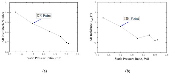
Figure 4.
The inlet flow conditions of AB (Aft Blade). (a) AB inlet Mach Number, (b) AB incidence
3.2. Loss Mechanism of the Tandem Blade in Typical Operating Conditions
In a conventional supersonic blade, the passage shock moves out of the channel and then coalesces with the leading edge shock with the increase of outlet static pressure. The supersonic tandem blade experiences a similar process. Due to the fact that flow field structures vary in different outlet static pressure conditions, it is necessary to analyze the flow characteristic and the loss mechanism in typical operating conditions to provide clear guidance for future optimum design. Figure 5 shows the proportion of the FB loss to the total loss in different outlet static pressures. It should be noted that the FB outlet reference surface is set between FB and AB during counting the FB loss. Consequently, the mixing loss of the FB wake in AB passage is counted into the AB loss. In the statistical method described, the FB loss proportion at the DE point exceeded 50%. Furthermore, the FB loss proportion increased with the outlet pressure, and it accounts for more than 80 percent of the total loss at the near stall (NS) point. In conclusion, controlling the FB loss in all operating conditions is the first priority in supersonic tandem blade optimization.
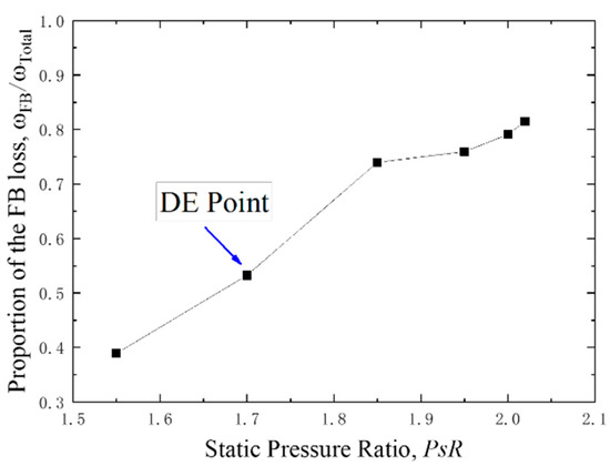
Figure 5.
The proportion of the FB loss to the total loss at inlet Mach number 1.2.
For further understanding of the supersonic tandem blade loss mechanism, the flow field structures in two typical operating conditions (DE and NS point) were analyzed in detail.
- DE point
According to the Mach contour plots at the DE point (Figure 6a), there is an obvious double-shock wave structure in the FB passage. Due to the transonic tandem rotor requiring a high stall margin, the rotor tip element needs to operate in a deep choke point, which makes the shock position move downstream of the blade passage. The FB passage shock intersects at 60 percent of the chord length in the pressure side and near the trailing edge in the suction side. On the other hand, the Mach number upstream of the shock on the AB suction side exceeds 1.3, and this leads to a strong shock wave/ boundary layer interaction and subsequent separation near the AB trailing edge.
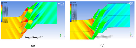
Figure 6.
The Mach contour plots at inlet Mach number 1.2. NS: Near Stall. (a) at the DE point, (b) at the NS point.
According to the entropy increment contours at the DE point (Figure 7a), the main physical mechanisms that lead to entropy increment can be summarized as follows: the shock wave loss in FB passage, mixing loss of the FB wake, and the separation loss of the AB boundary layer. Therefore, aiming to reduce the loss at the DE point, the intensity of FB leading edge shock, FB passage shock, and AB suction side shock should be controlled appropriately.
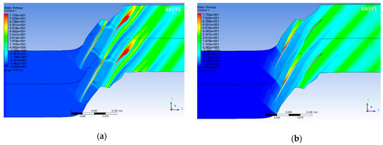
Figure 7.
The entropy increment contours at inlet Mach number 1.2. (a) at the DE point, (b) at the NS point.
- NS point
Since the FB loss proportion accounts for as much as 80 percent of the total loss at the NS point, controlling the increased rate of the FB loss in the positive incidence condition is the key method to increase the incidence range.
According to the Mach number contours and entropy increment contours at the NS point (Figure 6b and Figure 7b), the main physical mechanisms that lead to loss include the FB suction side shock loss, the FB shock wave/boundary layer interaction loss, and the FB wake mixing loss. It should be emphasized that these losses are all related to the intensity of the FB suction side shock. Therefore, aiming at increasing the incidence range, the FB suction side shock intensity growth rate with the incidence should be controlled carefully.
4. Optimal Design of the Tandem Blades
Based on the cognition of the supersonic tandem blade loss mechanism in typical operating conditions, in this section the basic airfoil was optimized with an inflow Mach number of 1.2. Under a supersonic inflow condition, the complicated shock wave structures represent the critical factor that implies the total pressure loss and strong aerodynamic interaction between FB and AB, so the core method is to control the shock wave structures. Since there are more than 10 degrees of freedom that describe integral tandem blade geometry, it would be an enormous work if all the variables were to be changed. Otherwise, for the consideration of limited strength factors mentioned previously, the AO/PP and blade equal solidity are fixed.
Consequently, the following two points should be emphasized. Firstly, during the optimization process, the AB needs to be moved independently to keep the AO/PP constant, and the tandem blade needs to be scaled to keep the blade equal solidity constant. Secondly, effects of the design parameters on blade performance may be opposite (e.g., the appropriate increase of the FB camber can lead to a decline of the loss at the DE point but a decline of incidence range simultaneously), so the optimization direction should be considered synthetically. Combined with the actual demand of the transonic fan, the optimization criterion in this paper is minimizing the loss at the DE point on the premise of a proper incidence range.
4.1. The Optimization Procedure
4.1.1. Adjustment to Reduce the Loss at the DE Point
- FB
Based on the flow characteristic analysis at the DE point in the previous section, it is clear that the key point to decrease the FB loss is to control the passage shock intensity. At the DE point, the passage shock intersects the pressure side at 60 percent chord length. Hence, the camber before 60 percent chord length was increased to form a stronger “sunken profile” pressure side. The supersonic flow near the pressure side decelerates through a series of compression waves and the shock intensity near the pressure side decreases significantly. On the other hand, the passage shock intersects the suction side near the trailing edge (Figure 6a). On the condition that the FB camber keeps constant, the flow turning angle is definite and the shock intensity near the suction side is difficult to control.
In conclusion, at the DE point the passage shock near the pressure side can be controlled by increasing the camber before 60% chord length, and there is no effective measure to intervene the passage shock near the suction side if the FB camber stays constant.
- AB
At the DE point, the AB loss can be reduced by controlling the suction side normal shock intensity. Therefore, the AB was optimized in the following two aspects.
Firstly, the AB camber line was adjusted. At the DE point, the AB works in a transonic condition with an inlet Mach number of 0.9. In basic scheme, the Mach number upstream of the shock on the AB suction side exceeds 1.3; consequently, the strong shock wave/ boundary layer interaction leads to the obvious flow separation. Therefore, the camber before the 45% chord length was reduced to control the suction side shock intensity.
Secondly, the AB incidence was reduced. As can be seen from the Mach contour plots (Figure 6a), the AB works in a positive incidence condition. This is due to the “nozzle effect” decreasing the static pressure on the AB suction side, shown in Figure 8. Consequently the streamline near the leading edge deflects toward the suction side, which leads to a higher incidence. Therefore, it is necessary to decrease the AB incidence to offset the “nozzle effect”.

Figure 8.
“Nozzle effect” in the tandem blade.
4.1.2. Adjustment to Increase the Incidence Range
- FB
As stated above, the DE point loss coefficient can be controlled by increasing the FB camber before 60% chord length. On the other hand, the forward loading will inevitably lead to a stronger “convex profile” suction side, resulting in a stronger shock wave. This causes a rapid increase of Mach number upstream of the shock with the incidence incline, and the reduction of incidence range. In brief, it is contradictory to decrease the DE point loss and increase the incidence range by adjusting the FB camber distribution.
Massive simulation results show that an appropriate solidity ratio can increase the incidence range under the constraint of a certain the FB camber line. Because the shock wave/ boundary layer interaction is restrained in a proper FB chord, the boundary layer does not yet fully develop before it flows through the FB surface.
- AB
A large number of numerical simulation studies indicate that the AB affects the blade loss (as shown in Section 4.1.1), but it has little impact on the incidence range, so no additional explanation is needed.
4.2. Comparison of the Geometries Between Basic and Optimization Scheme
The comparison of basic and optimization airfoil is shown in Figure 9. The main changes are as follows:
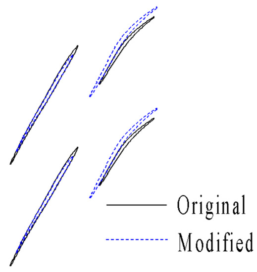
Figure 9.
Comparison of basic and optimization airfoil.
- Solidity ratio (σFB/σAB)—the solidity ratio was decreased from 1.6:1 to 1:1 to achieve a higher incidence range and the total equivalent chord length remained constant;
- FB camber line distribution—the camber before the 60% chord length was increased to suppress the shock intensity near the FB pressure side;
- AB camber line distribution—the camber before the 40% chord length was decreased to suppress the shock intensity on the AB suction side;
- AB inlet metal angle—the AB inlet metal angle was decreased by 1.5° to adapt to the FB outflow direction.
4.3. Comparison of the Blade Performance between the Basic and Optimization Scheme
Comparison of tandem blade performances (static pressure ratio–total pressure loss and incidence–total pressure loss) between the basic and optimization scheme are shown in Figure 10. The total pressure loss coefficient at the DE point declines by 20% and the minimum loss declines by 6.5%. Meanwhile, the incidence range increases by 0.5° in the optimization scheme. The change of the FB and AB losses is shown in Figure 10c, and the results indicate that the reduction of the FB loss is more obvious, especially in the higher back pressure. The tandem overall and single blade diffusion factors are shown in Figure 11. The maximum diffusion factor inclines slightly, mainly due to the increase of the FB load limit at the NS point.
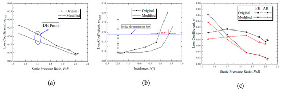
Figure 10.
Comparison of the basic and optimized blade performances. (a) Static pressure ratio–total pressure loss coefficient, (b) Incidence–total pressure loss coefficient, (c) total pressure loss coefficient of FB and AB.
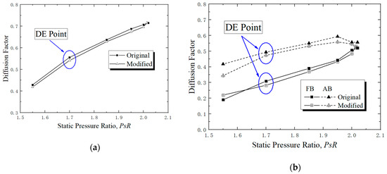
Figure 11.
Comparison of the basic and optimized blade diffusion factors. (a) Diffusion factor of the tandem blade, (b) Diffusion factor of the single blade.
The Mach contour plots and blade isentropic Mach number distributions in two typical working conditions are shown in Figure 12 and Figure 13. The reasons that the optimization scheme achieved a better blade loss can be summarized as follows. Firstly, the FB passage shock angle decreased compared to the baseline, as shown in Figure 6a and Figure 12a. Secondly, the FB passage shock intensity decreased, as shown in Figure 13a. Thirdly, the airflow accelerated more slowly near the modified AB suction side, as shown in Figure 13a.
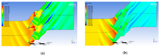
Figure 12.
The optimal blade Mach contour plots in typical working conditions. (a) At the DE point, (b) At the NS point.
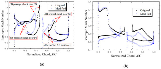
Figure 13.
Comparison of the blade isentropic Mach distribution in typical working conditions. (a) At the DE point, (b) At the NS point.
5. Conclusions
In this paper, the tandem blade with an inflow Mach number of 1.2 was studied. The present research was motivated by exploring the flow mechanism of the tandem blade under a complex interaction shock structure. Furthermore, an optimization principle for a supersonic tandem blade was carried out and verified by using the CFD method. The main conclusions follow:
- With an inflow Mach number of 1.2, the total pressure loss is difficult to control because of the complicated flow structures at the DE point; there is an obvious double-shock wave structure located rearward in the FB passage and a normal shock on the AB suction side. The complicated shock waves cause a strong interaction between FB and AB, and a different optimization strategy compared to conventional blade.
- The FB loss dominates the overall loss in all of the operating conditions. It exceeds 50% of the total loss at the DE point, and accounts for more than 80% at the NS point. Therefore, the optimization aiming at FB is of decisive significance to improve the blade performance.
- The conventional supersonic airfoil is not the optimum choice for the supersonic tandem blade due to the aerodynamic interaction between FB and AB. In this paper, the tandem blade was optimized considering this aerodynamic interaction by controlling the FB passage shock intensity near the pressure side, the AB shock intensity near the suction side, and the AB incidence. The numerical simulation results of the optimization scheme show that the total pressure loss declines by 20% at the DE point and the incidence range increases by about 0.5°.
It is noted that to the best knowledge of the authors, the supersonic tandem blade flow mechanism and its optimization is published for the first time, although some characteristics of the tandem blade with local shock wave were investigated previously [9,18]. The result constitutes a step forward in understanding the complex shock structure and optimization principle for a supersonic tandem blade, and it shows good application prospects for a transonic axial compressor/fan with a tandem blade.
Author Contributions
Conceptualization, B.L. and X.Y.; methodology, Y.T.; software, Y.T.; validation, Y.T.; formal analysis, Y.T.; investigation, Y.T.; data curation, Y.T.; writing—original draft preparation, Y.T.; writing—review and editing, Y.W.; project administration, Y.T.; funding acquisition, Y.T. All authors have read and agreed to the published version of the manuscript.
Funding
This research was funded by “Equipment development department of the Central Military Commission, grant number 614270202031804”.
Acknowledgments
The authors would like to acknowledge David’s help in improving the grammar of the manuscript.
Conflicts of Interest
The authors declare no conflict of interest.
References
- Biollo, R.; Benini, E. Recent advances in transonic axial compressor aerodynamics. Prog. Aerosp. Sci. 2013, 56, 1–18. [Google Scholar] [CrossRef]
- Sulam, D.H.; Keenan, M.J.; Flynn, J.T. Single-Stage Experimental Evaluation of Highly-Loaded High-Mach-Number Compressor Stages Part 2: Data and Performance Multiple-Circular-arc Rotor. Available online: https://core.ac.uk/download/pdf/80656364.pdf (accessed on 1 July 2020).
- Brent, J.A.; Clemmons, D.R. Single-Stage Experimental Evaluation of Tandem-Airfoil Rotor and Stator Blading for Compressors Part 8: Final Report; NASA Center for Aerospace Information: Hanover, MD, USA, 1974; NASA-CR-134713.
- Bammert, K.; Beelte, H. Investigation of an axial flow compressor with tandem cascade. J. Eng. Power 1980, 102, 971. [Google Scholar] [CrossRef]
- Bammert, K.; Staude, R. Optimization for Rotor Blades of Tandem Design for Axial Flow Compressors. J. Eng. Power. 1980, 102, 369. [Google Scholar] [CrossRef]
- Wennerstrom, A.J. Highly loaded axial flow compressors: History and current developments. J. Turbomach. 1990, 112, 567–578. [Google Scholar] [CrossRef]
- Nezym, V.Y.; Polupan, G.P. A New Statistical-Based Correlation for the Compressor Tandem Cascade Parameters Effects on the Loss Coefficient. In Proceedings of the ASME Turbo Expo, Montreal, QC, Canada, 14 May 2007. GT2007-27245. [Google Scholar]
- McGlumphy, J.; Ng, W.-F. Numerical Investigation of Tandem Airfoils for Subsonic Axial-flow Compressor Blades. J. Turbomach. 2009, 131, 021018. [Google Scholar] [CrossRef]
- Hoeger, M.; Baier, D. High Turning Compressor Tandem Cascade for High Subsonic Flows, Part1: Aerodynamic Design. In Proceedings of the AIAA, San Diego, CA, USA, 31 July 2011. GT2011-5602. [Google Scholar]
- Hoeger, M.; Baier, D. High Turning Compressor Tandem Cascade for High Subsonic Flows, Part2: Numerical and Experimental Investigations. In Proceedings of the AIAA, San Diego, CA, USA, 31 July 2011. GT2011-5602. [Google Scholar]
- Liu, B.J.; Du, F. Development of a Preliminary Design Method for Subsonic Splittered Blades in Highly Loaded Axial-Flow Compressors. Appl. Sci. 2017, 7, 283. [Google Scholar] [CrossRef]
- Nehad, A.S.; Asiful, H.S. Natural convection of bio-nanofluid between two vertical parallel plates with damped shear and thermal flux. J. Mol. Liq. 2019, 296, 111575. [Google Scholar]
- Basma, S.; Ganesh, K. Slip flow and radiative heat transfer behavior of Titanium alloy and ferromagnetic nanoparticles along with suspension of dusty fluid. Microsyst. Technol. 2019, 290, 111223. [Google Scholar]
- Samuel, O.A.; Onanaye, A.S. Evaluation of heat irreversibility in couple stress falling liquid films along heated inclined substrate. J. Clean. Prod. 2019, 239, 117608. [Google Scholar]
- Schlaps, R.C.; Shahpar, S. Automatic Three-Dimensional Optimization of a Modern Tandem Compressor Vane. In Proceedings of the ASME Turbo Expo, Düsseldorf, Germany, 16 June 2014. GT2014-26762. [Google Scholar]
- Ju, Y.; Zhang, C. Multi-objective Optimization Design Method for Tandem Compressor Cascade at Design and off Design Condition. In Proceedings of the ASME Turbo Expo, Glasgow, UK, 14 June 2010. GT2010-22655. [Google Scholar]
- Schneider, T.; Kozulivic, D. Flow Characteristics of Axial Compressor Tandem Cascades at Large Off-design Incidence Angles. In Proceedings of the ASME Turbo Expo, San Antonio, CA, USA, 3 June 2013. GT2013-94708. [Google Scholar]
- Hergt, A.; Siller, U. About Transonic Compressor Tandem Design—A Principle Study. In Proceedings of the ASME Turbo Expo, Montréal, QC, Canada, 15 June 2015. GT2015-42115. [Google Scholar]
- Kumar, A.; Pradeep, A.M. Performance Evaluation of a Tandem Rotor under Design and Off-design Operation. In Proceedings of the ASME Turbo Expo, Oslo, Norway, 11 June 2018. GT2018-75478. [Google Scholar]
- Kumar, A. Design and off-design behavior of a tandem rotor stage. Inst. Mech. Eng. Part G-J. Aerosp. Eng. 2020, 234, 927–942. [Google Scholar] [CrossRef]
- Cumpsty, N.A. Compressor Aerodynamics, 2nd ed.; Krieger Publishing Company: Malabar, FL, USA, 2004. [Google Scholar]
- Venturelli, G.; Benini, E. Kriging-assisted Design Optimization of S-shape Supersonic Compressor Cascades. Aerosp. Sci. Technol. 2016, 58, 275–297. [Google Scholar] [CrossRef]


© 2020 by the authors. Licensee MDPI, Basel, Switzerland. This article is an open access article distributed under the terms and conditions of the Creative Commons Attribution (CC BY) license (http://creativecommons.org/licenses/by/4.0/).