Featured Application
Minimization of reflection losses in conventional and light weight PV modules.
Abstract
Calcium fluoride (CaF2) is deposited via vacuum thermal evaporation on borosilicate glass to produce an anti-reflection coating for use in solar modules. Macleod’s essential simulation is used to optimize the thickness of the CaF2 coating on the glass. Experimentally, a 120 ± 4 nm-thin CaF2 film on glass shows an average increase of ~4% in transmittance and a decrease of ~3.2% in reflectance, respectively, when compared to that of uncoated glass (Un CG), within the wavelength spectrum of approximately 350 to 1100 nm. The electrical PV performance of CaF2-coated glass (CaF2-CG) was analyzed for conventional and lightweight photovoltaic module applications. An improvement in the short-circuit current (Jsc) from 38.13 to 39.07 mA/cm2 and an increase of 2.40% in the efficiency (η) was obtained when CaF2-CG glass was used instead of Un CG in a conventional module. Furthermore, Jsc enhancement from 35.63 to 36.44 mA/cm2 and η improvement of 2.32% was observed when a very thin CaF2-CG was placed between the polymethyl methacrylate (PMMA) and solar cell in a lightweight module.
1. Introduction
A typical photovoltaic (PV) module can be classified as a conventional or light weight module. In a conventional module, glass is used as a top cover and accounts for approximately 70% of the module weight. On the contrary, in lightweight c-Si PV modules, glass is replaced by acrylic (poly methyl methacrylate: PMMA) or other polymers [1,2,3] to enable such modules to be used in applications where the light weight of the PV module must be limited. Reflection losses are one of the major issues that decrease the effective efficiency of PV modules. A reflection loss of approximately 8% occurs at the front surface of the glass and PMMA because their higher refractive indexes are higher than that of air [4]. This issue can be resolved by using an anti-reflection coating (ARC) material with an ultra-low refractive index (much lower than that of glass) on the front surface of glass. The use of ARC has already been recognized as crucial for various optical and PV panel applications [5,6]. A simple and cost-effective ARC comprises a single layer coating of a material with a refractive index suitable for the desired wavelength spectrum [7]. In this context, optical coatings of fluoride and oxide materials have been investigated widely owing to their higher band gap. Optical coatings have been widely used in the areas of optoelectronics [8], optics [9], and PV modules [10].
Recently, magnesium fluoride (MgF2) has gained much attention as an ARC suitable for application on the front cover of PV modules, owing to its low refractive index (n = 1.37 at 600 nm); however, it was proven to be less durable in outdoor environments [11]. CaF2 belongs to a similar category of materials and has been widely investigated by the optics community [12], owing to its lower refractive index (1.43 at 600 nm), when compared to that of glass substrates. It also has a broad transmittance spectrum from 130 to 10,000 nm [13]. Furthermore, it exhibits less solubility in water when compared to MgF2 [14], which can be a significant factor in view of the chemical resistance towards environmental conditions. Furthermore, it is also used as an ARC in outdoor conditions, optical applications, IR imaging system, and photolithography systems [15]. Therefore, the application of CaF2 as an ARC for PV modules has been explored in this work. It is important to note that the excellent surface uniformity of ARC is highly dependent on the deposition technique. Numerous techniques have been introduced for depositing CaF2 thin films on substrates for various purposes such as electron beam evaporation [16,17,18,19], radio frequency magnetron sputtering [20], molecular beam epitaxial [21], pulsed laser deposition [22,23] and thermionic vacuum arc [24]. Of these techniques, thermal evaporation has been found to be the most suitable because of its advantages of large-area deposition, low-temperature, and simple process, and it has been proven to be a cheap fabrication process [25].
In this work, a CaF2 coating was deposited by vacuum thermal evaporation on borosilicate glass (BSG). In this process, the substrates were tilted and rotated at constant speed, resulting in the uniform deposition of the material. The thickness of the ARC was first optimized using the Essential Macleod simulation tool. The optical properties of the thermally evaporated CaF2 on the glass substrate were investigated using ultraviolet–visible spectroscopy. The electrical performance of the solar cell (SC) was compared by replacing the uncoated glass (Un CG), with CaF2-coated glass (CG) in a conventional PV module and placing a thin CaF2-CG between the PMMA and SC in the light weight PV module.
2. Materials and Methods
An SC with an active area of ~2.5 × 2.8 cm2 was used as a reference SC. The BSG and PMMA sheets were cut according to the active area of the SC. First, the substrates were cleaned sequentially with acetone, isopropyl alcohol (IPA) and deionized water (DIW) for 10 min each in an ultra-sonic bath. The BSG substrates were dried by blowing N2 gas and then heated on a hot plate at ~100 °C for 20 min to remove moisture. The cleaned BSG substrates were loaded immediately into the vacuum thermal evaporation chamber to deposit the thin CaF2 as the ARC. The deposition was performed at ~110 A current and under a pressure of ~10−6 torr. The thickness of the CaF2 coating on the glass was measured by nano-view Spectroscopic Ellipsometer MF-1000 which was 120 ± 4 nm. The PMMA was cleaned using soapy water and dried by blowing N2 gas. Finally, the electrical parameters such as the short circuit current (Jsc) and efficiency (η) were characterized by a light-current–voltage (LIV) measurement system under Air Mass 1.5 G 1 sun illumination conditions (100 mW/cm2). The potential was swept from short circuit condition towards open circuit. The step voltage and delay time were 10 mV and 1 ms, respectively.
3. Results and Discussions
3.1. Structure Characterization
The morphology of the thin film was observed using field-emission scanning electron microscopy (FE-SEM; JEOL JSM-7600F). The cross-sectional FE-SEM image of the CaF2 film on glass are clearly shown in Figure 1a. The image showed the information about the ARC thickness, its uniformity and the interaction between the coating and substrate. X-ray diffraction (XRD) patterns were recorded in a 2θ range of 20–70 degrees using an X-ray diffractometer (Bruker, D8 Advance, Turbo X-ray source 18 KW). The typical XRD pattern for the CaF2 thin film on glass are presented in Figure 1b. It shows that the CaF2 film is polycrystalline and has a strongest peak of 111, which is in good agreement with the Bannon and Coogan result [26]. The subsequent diffraction lines at 49.6 and 55.6 were identified as 220 and 311 reflexes of the CaF2 phase, respectively [27].
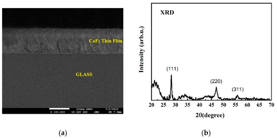
Figure 1.
(a) Cross sectional FE-SEM image of CaF2 thin film; (b) XRD pattern for the CaF2 film.
3.2. Optical Characterization
The optical characteristics of the CaF2-CG were studied in the wavelength range of ~350 to 1100 nm. By varying the thickness of the coating material, the optical properties of the thin film deposited on the substrate can be changed [28]. The prototype of the Macleod simulation parameters are shown in the Supporting Document.
3.2.1. Reflectance, Transmittance and Absorbance
The transmittance and absorbance of the Un CG and CaF2-CG were measured using an ultraviolet–visible spectrophotometer (SCINCO S-3100). The reflectance can be calculated using the relation:
where T is the transmittance, and A is the absorbance at wavelength.
The spectral behaviors of transmittance and reflectance of the Un CG and CaF2-CG, obtained through simulations and experiments, are compared in Figure 2. The Un CG shows an average transmittance and reflectance of ~91% and 8.1%, respectively, across the wide spectrum from ~350 to 1100 nm (Figure 2a), whereas CaF2-CG shows improved an transmittance and reflectance of ~95.7% and 4.3%, respectively, in the broad spectrum of ~ 350–1100 nm as shown in Figure 2b. The observed results are in good agreement with the results reported by Hahn et al. [29] and exhibit an improvement in the result, as discussed by Cetin et al. in their study on vacuum-evaporated CaF2 [24]. The observed absorbance is the minimum (~0.015%) at 600 nm, which is quite low as expected.
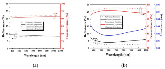
Figure 2.
Comparison of the simulated and experimentally obtained optical spectra of: (a) the uncoated and (b) the CaF2-coated borosilicate glass (BSG).
3.2.2. Incidence Angle and Refractive Index
The optical characteristics of the PV panel are mainly dependent on the incident angle of light. The influence of different incident angles on the reflectance and transmittance of the CaF2-CG computed using Essential Macleod is clearly shown in Figure 3a. The graph shows that the reflectance increases and the transmittance decreases as we go from a low incidence angle to a high incidence angle, and the results are in good agreement with the analysis presented in [30].
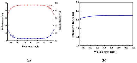
Figure 3.
(a) Influence of the different incident angles on the reflectance and transmittance; (b) refractive index.
The refractive index (n) provides knowledge regarding the local fields, electronic polarization and the phase velocity of light spreading inside a material [25]. The refractive index depends on the deposition technique of coating because the mass density and crystal orientation of the material influences n. The Lorentz–Lorenz equation provides information on the increase in the value of n with the increase in the film density [31]. The dependence of n for the CaF2-coated film on BSG over a broad range of wavelength is shown in Figure 3b. We used the Cauchy model for fitting the data from the VB-250 VASE ellipsometer for determining the n value of the produced CaF2 thin film. The measured refractive index of ~1.39 at 600 nm indicated the excellent transparency of ~95% of CaF2-CG. There was good improvement in the refractive index, as a result of the vacuum thermal evaporation process, when compared to that presented in the literature and that of bulk material [24].
3.3. Electrical Characterization
As a result of the improvement in the optical characteristics of CaF2-CG, a similar improvement was expected in the electrical parameters when the CaF2-CG was placed on a pristine SC.
3.3.1. Conventional Module
The performance of the ARC was analyzed by placing the CaF2-CG on an SC, as shown in Figure 4. The structure represents the conventional module model in which the Un CG is replaced by the CaF2-CG.
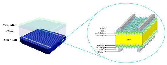
Figure 4.
CaF2-coated BSG on solar cell to represent the conventional photovoltaic (PV) module model.
Table 1 shows a comparison of the different PV parameters of the Un CG and CG samples on SC, having average and corresponding standard deviation values. The data were analyzed after recording the performance data of five different samples.

Table 1.
Comparison of the different electrical parameters of a solar cell (SC), CaF2-coated glass (CG)/SC and uncoated glass (Un CG)/SC measured under 1 sun illumination (100 mW/cm2).
Statistical Analysis
The analysis showed that there is a reasonable improvement being observed in Jsc and η as a result of applying ARC on glass. The CG on SC have an average Jsc and standard deviation of 39.03 ± 0.45 with an effective η of 20.39 ± 0.24, respectively, as compared to SC having Un CG with Jsc and standard deviation of 38.10 ± 0.43, with an effective η of 19.88 ± 0.24, respectively, as shown in Figure 5a. The CG couples, lighter in the device, enhance the Jsc and η of the structure [32]. The increase in effective η of 2.40% is observed by increasing the transmittance of ~4% after applying ARC on glass as compared to Un CG. The relation between the current–voltage (J–V) curve for the Un CG and CG on SC, measured under 1 sun illumination (100 mW/cm2) is shown in Figure 5b.
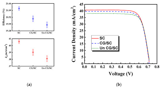
Figure 5.
(a) Statistical analysis of Jsc and η on the SC, CG/SC and the Un CG/SC. The graph shows the data from five different cells, which were analyzed with standard deviation values; (b) the J–V characteristics of a SC, CG/SC and Un CG/SC.
Supporting Documents show the J–V curve for five different PV module structures.
3.3.2. Light Weight Module
The addition of thin glass between the PMMA and SC can help the surface mechanical integrity and the reduce moisture in a light weight PV module. It improves the reliability of module. The performance of the coating in the light weight module model was analyzed by placing the CaF2-CG between the PMMA and SC. Table 2 shows a comparison of the different PV parameters by placing the Un CG and CG between the PMMA and SC having average and corresponding standard deviation values. The data were analyzed after recording the performance data of five different samples.
Table 2.
Comparison of the electrical parameters of a the polymethyl methacrylate (PMMA)/SC, PMMA/CG/SC and PMMA/Un CG/SC measured under 1 sun illumination (100 mW/cm2).
Statistical Analysis
The analysis showed that there is a reasonable improvement being observed in Jsc and η as a result of putting CG between PMMA and SC. The PMMA/CG/SC have an average Jsc and standard deviation of 36.43 ± 0.43 with an effective η of 19.64 ± 0.24 as compared to PMMA/Un CG/SC, which have Jsc and a standard deviation of 35.65 ± 0.36 with an effective η of 19.17 ± 0.20, respectively, as shown in Figure 6a. The relation between the current density–voltage (J–V) curve for the Un CG and CG between the PMMA and SC, measured under 1 sun illumination (100 mW/cm2), is shown in Figure 6b.
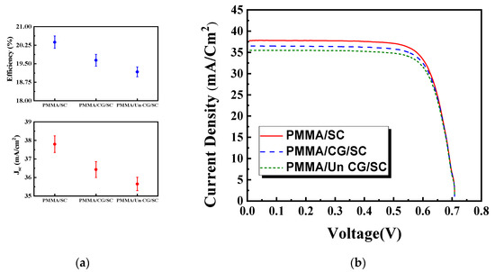
Figure 6.
(a) Statistical analysis of Jsc and η on the PMMA/SC, PMMA/CG/SC and PMMA/Un CG/SC. The graph shows the data from five different SCs, which were analyzed with standard deviation values; (b) the J–V characteristics of a PMMA/SC, PMMA/CG/SC and PMMA/Un CG/SC.
Supporting Documents show the J–V curve for five different light weight PV module structures.
3.4. Weather-Resitance Test
The brine pollution as a weather resistant test was performed to check the adhesive property of ARC on glass [33]. The coated glass was immersed in a 0.5 M NaCl solution for 30 min. The transmittance of CG before performing the test was 95.12% while it became 94.95% after the test. The decrease of only 0.18% was seen in transmittance. The results suggested that this ARC has weather-resistant ability.
4. Conclusions
In summary, the optical properties of a CaF2 as ARC using vacuum thermal evaporation on borosilicate glass substrates are investigated successfully. The optical characteristics of uncoated and CaF2-CG were simulated using Macleod simulations and compared experimentally. In addition, the electrical performance of the CaF2-CG was analyzed for conventional and light weight module applications. The results showed reasonable improvement in the short circuit current density and module efficiency. The findings suggest that, because of the lower solubility of CaF2 when compared to that of MgF2, the CaF2-ARC on glass can be beneficial for improving the electrical performance of solar cell modules, and can be utilized effectively in both types of PV modules (conventional and light weight). The CaF2-ARC showed a good weather-resistant ability. Moreover, various treatments like annealing and hexamethyldisilazane on coated surface could be an interesting topic in the future to further improve the optical properties and environmental sustainability of this material on glass.
Author Contributions
Conceptualization, Y.H.C., and M.A.Z.; methodology, Y.H.C.; software, M.A.Z.; validation, S.Q.H., and Y.H.C.; formal analysis, M.A.Z., and S.Q.H.; investigation, M.A.Z.; data curation, M.A.Z., and S.Q.H.; writing—original draft preparation, M.A.Z.; writing—review and editing, M.A.Z., and S.Q.H.; supervision, Y.H.C., and J.Y.; project administration, Y.H.C., and J.Y.; funding acquisition, Y.H.C., and J.Y. All authors have read and agreed to the published version of the manuscript.
Funding
This research was funded by the Korea Institute of Energy Technology Evaluation and Planning, Korea Government.
Acknowledgments
This research was supported by the Korea Institute of Energy Technology Evaluation and Planning (KETEP) 20193010014850.
Conflicts of Interest
The authors declare no conflict of interest.
References
- Martins, A.C.; Chapuis, V.; Virtuani, A.; Ballif, C. Ultra-Lightweight PV module design for Building Integrated Photovoltaics. In Proceedings of the 2017 IEEE 44th Photovoltaic Specialist Conference (PVSC), Washington, DC, USA, 25–30 June 2017. [Google Scholar]
- Kajisa, T.; Miyauchi, H.; Mizuhara, K.; Hayashi, K.; Tokimitsu, T.; Inoue, M.; Hara, K.; Masuda, A. Novel lighter weight crystalline silicon photovoltaic module using acrylic-film as a cover sheet. Jpn. J. Appl. Phys. 2014, 53, 092302. [Google Scholar] [CrossRef]
- Martins, A.C.; Chapuis, V.; Sculati-Meillaud, F.; Virtuani, A.; Ballif, C. Light and durable: C omposite structures for building-integrated photovoltaic modules. Prog. Photovolt. Res. Appl. 2018, 26, 718–729. [Google Scholar] [CrossRef]
- Ilse, K.; Pfau, C.; Miclea, P.T.; Krause, S.; Hagendorf, C. Quantification of abrasion-induced ARC transmission losses from reflection spectroscopy. In Proceedings of the 2019 IEEE 46th Photovoltaic Specialists Conference (PVSC), Chicago, IL, USA, 16–21 June 2019; pp. 2883–2888. [Google Scholar]
- Murata, T.; Ishizawa, H.; Motoyama, I.; Tanaka, A. Investigations of MgF2 optical thin films prepared from autoclaved sol. J. Sol-Gel Sci. Technol. 2004, 32, 161–165. [Google Scholar] [CrossRef]
- Raut, H.K.; Ganesh, V.A.; Nair, A.S.; Ramakrishna, S. Anti-reflective coatings: A critical, in-depth review. Energy Environ. Sci. 2011, 4, 3779–3804. [Google Scholar] [CrossRef]
- Nubile, P. Analytical design of antireflection coatings for silicon photovoltaic devices. Thin Solid Film. 1999, 342, 257–261. [Google Scholar] [CrossRef]
- Ramamoorthy, K.; Kumar, K.; Chandramohan, R.; Sankaranarayanan, K.; Saravanan, R.; Kityk, I.V.; Ramasamy, P. High optical quality IZO (In2Zn2O5) thin films by PLD–A novel development for III–V opto-electronic devices. Opt. Commun. 2006, 262, 91–96. [Google Scholar] [CrossRef]
- Fujihara, S.; Kadota, Y.; Kimura, T. Role of organic additives in the sol-gel synthesis of porous CaF2 anti-reflective coatings. J. Sol-Gel Sci. Technol. 2002, 24, 147–154. [Google Scholar] [CrossRef]
- Sharma, P.K.; Mellott, N.P.; Taylor, T.J. Solar Cell with Antireflective Coating Comprising Metal Fluoride and/or Silica and Method of Making Same. U.S. Patent Application No. 11/516,671, 27 March 2008. [Google Scholar]
- Kaminski, P.M.; Lisco, F.; Walls, J.M. Multilayer broadband antireflective coatings for more efficient thin film CdTe solar cells. IEEE J. Photovolt. 2013, 4, 452–456. [Google Scholar] [CrossRef]
- Retherford, R.S.; Sabia, R.; Sokira, V.P. Effect of surface quality on transmission performance for (111) CaF2. Appl. Surf. Sci. 2001, 183, 264–269. [Google Scholar] [CrossRef]
- Rehmer, A.; Scheurell, K.; Kemnitz, E. Formation of nanoscopic CaF2 via a fluorolytic sol–gel process for antireflective coatings. J. Mater. Chem. C 2015, 3, 1716–1723. [Google Scholar] [CrossRef]
- Barta, Č.; Fendrych, F.; Recker, K.; Tříska, A.; Wallrafen, F. Influence of crystallisation conditions on the microtexture of the directionally solidified eutectic of the MgF2-CaF2 system. Cryst. Res. Technol. 1990, 25, 1287–1298. [Google Scholar] [CrossRef]
- Yan, J.; Syoji, K.; Tamaki, J.I. Crystallographic effects in micro/nanomachining of single-crystal calcium fluoride. J. Vac. Sci. Technol. B Microelectron. Nanometer Struct. Process. Meas. Phenom. 2004, 22, 46–51. [Google Scholar] [CrossRef]
- Lee, C.H.; Qi, J.; Lee, S.T.; Hung, L.S. Epitaxial diamond on a Si/CaF2/Ir substrate. Diam. Relat. Mater. 2003, 12, 1335–1339. [Google Scholar] [CrossRef]
- Klust, A.; Bierkandt, M.; Wollschläger, J.; Müller, B.H.; Schmidt, T.; Falta, J. Low-temperature interface structure of CaF2/Si (111) studied by combining x-ray standing waves with component-resolved photoemission. Phys. Rev. B 2002, 65, 193404. [Google Scholar] [CrossRef]
- Wollschläger, J.; Hildebrandt, T.; Kayser, R.; Viernow, J.; Klust, A.; Bätjer, J.; Hille, A.; Schmidt, T.; Falta, J. Effects of electron irradiation on the structure and morphology of CaF2/Si (111). Appl. Surf. Sci. 2000, 162, 309–318. [Google Scholar] [CrossRef]
- Klust, A.; Kayser, R.; Wollschläger, J. Growth kinetics of CaF2/Si (111) for a two-step deposition. Phys. Rev. B 2000, 62, 2158. [Google Scholar] [CrossRef]
- Cook, J.G.; Yousefi, G.H.; Das, S.R.; Mitchell, D.F. RF magnetron deposition of calcium fluoride. Thin Solid Film. 1992, 217, 87–90. [Google Scholar] [CrossRef]
- Sata, N.; Eberman, K.; Eberl, K.; Maier, J. Mesoscopic fast ion conduction in nanometre-scale planar heterostructures. Nature 2000, 408, 946–949. [Google Scholar] [CrossRef]
- Maki, T.; Okamoto, K.; Sugiura, M.; Hosomi, T.; Kobayashi, T. The great improvement of surface smoothness of CaF2 in pulsed laser deposition even under the two-photon absorption process. Appl. Surf. Sci. 2002, 197, 448–451. [Google Scholar] [CrossRef]
- Shushtarian, S.S.; Ogale, S.B.; Chaudhari, G.N.; Singh, P.; Rao, V.J. Epitaxial growth of CaF2 thin films on (100) GaAs by pulsed-laser deposition and in-situ annealing. Mater. Lett. 1991, 12, 335–338. [Google Scholar] [CrossRef]
- Çetin, N.E.; Korkmaz, Ş.; Elmas, S.; Ekem, N.; Pat, S.; Balbağ, M.Z.; Tarhan, E.; Temel, S.; Özmumcu, M. The structural, optical and morphological properties of CaF2 thin films by using Thermionic Vacuum Arc (TVA). Mater. Lett. 2013, 91, 175–178. [Google Scholar] [CrossRef]
- Manjunatha, K.N.; Paul, S. Investigation of optical properties of nickel oxide thin films deposited on different substrates. Appl. Surf. Sci. 2015, 352, 10–15. [Google Scholar] [CrossRef]
- Bannon, J.; Coogan, C.K. Thin evaporated calcium fluoride films. Nature 1949, 163, 62–63. [Google Scholar] [CrossRef]
- Tsai, R.Y.; Shiau, S.C.; Lin, D.; Ho, F.C.; Hua, M.Y. Ion-assisted codeposition of CaF2-rich CaF2–TiO2 composites as infrared-transmitting films. Appl. Opt. 1999, 38, 5452–5457. [Google Scholar] [CrossRef] [PubMed]
- Muley, S.V.; Ravindra, N.M. Emissivity of electronic materials, coatings, and structures. Jom 2014, 66, 616–636. [Google Scholar] [CrossRef]
- Hahn, D. Calcium fluoride and barium fluoride crystals in optics: Multispectral optical materials for a wide spectrum of applications. Opt. Photonik 2014, 9, 45–48. [Google Scholar] [CrossRef]
- Sun, C.C.; Chien, W.T.; Moreno, I.; Hsieh, C.T.; Lin, M.C.; Hsiao, S.L.; Lee, X.H. Calculating model of light transmission efficiency of diffusers attached to a lighting cavity. Opt. Express 2010, 15, 6137–6148. [Google Scholar] [CrossRef]
- Washizu, E.; Yamamoto, A.; Abe, Y.; Kawamura, M.; Sasaki, K. Optical and electrochromic properties of RF reactively sputtered WO3 films. Solid State Ion. 2003, 165, 175–180. [Google Scholar] [CrossRef]
- Ballif, C.; Dicker, J.; Borchert, D.; Hofmann, T. Solar glass with industrial porous SiO2 antireflection coating: Measurements of photovoltaic module properties improvement and modelling of yearly energy yield gain. Sol. Energy Mater. Sol. Cells 2004, 82, 331–344. [Google Scholar] [CrossRef]
- Yuan, Y.; Chen, Y.; Chen, W.L.; Hong, R.J. Preparation, durability and thermostability of hydrophobic antireflective coatings for solar glass covers. Sol. Energy 2015, 118, 222–231. [Google Scholar] [CrossRef]


© 2020 by the authors. Licensee MDPI, Basel, Switzerland. This article is an open access article distributed under the terms and conditions of the Creative Commons Attribution (CC BY) license (http://creativecommons.org/licenses/by/4.0/).