Abstract
Heavy-wheeled vehicles with articulated hydraulic steering systems are widely used in construction, road building, forestry, and agriculture, as transport units and tool-carriers because they have many unique advantages that are not available in car steering systems, based on the Ackermann principle, such as—high cross-country mobility, excellent maneuverability, and high payload and lift capacity, due to heavy axles components. One problem that limits their speed of operation and use efficiency is that they have poor directional stability. During straight movement, articulated tractors’ deviate from a straight line and permanent driver correction is required. This limits the vehicles’ speed and productivity. In this study, we describe a driver-aid system concept that would improve the directional stability of articulated vehicles. Designing such a system demands a comprehensive knowledge of the reasons for the snaking phenomenon and driver behaviors. The results of our articulated vehicle directional stability investigation are presented. On this basis, we developed models of articulated vehicles with hydraulic steering systems and driver interaction. We next added the stabilizing system to the model. A simulation demonstrated the possibility of directional stability improvement.
1. Introduction
Wheel machines with an articulated frame due to rigid axles, large tires, and hydraulic steering systems have many unique features, such as high maneuverability, high cross-country mobility, high payload capacity, and high durability and reliability, with low manufacturing costs, as a result of the simplicity of construction and the serial, mass production of components. For these reasons, they are widely used with high efficiency in agriculture like heavy tractors; in forestry, as tree-harvesters and forwarders for transport tasks; in mining sites as transportation vehicles, and on construction and mining sites, as loaders for realization load and carry tasks, and as dumpers for hauling and transportation tasks. According to Petraska et al. [1], transportation productivity mainly depends on average speed. Lopatka et al. [2] indicated that this speed for articulated vehicles is mainly limited by the snaking phenomenon—low direction stability of machine movement. According to Meng et al. [3], the average speed of an articulated hauler on construction sites is about 25 km/h, with a top speed of 54 km/h. According to previous studies [2,4,5], low directional stability demands higher effort from drivers, increasing their concentration levels; additionally, cases of dynamic loads on bearings in joints and in the hydraulic cylinder are a serious problem. The robotization of such equipment is a main development trend, and according to Alshaer et al. [6], the dynamics of vehicle steering systems are critical for path planning for articulated vehicles. Wider use of articulated vehicles in transport applications and increasing their productivity require improvements to their average speed, by limiting the snaking phenomenon at high speeds. The effective realization of transport tasks requires duplication of road speed and achieving about 60 km/h, during driving in good road conditions.
The low lateral stability of articulated machines is a broadly known problem; for this reason, the international standard [7] was developed. It describes the method of dynamic testing of vehicle stability when moving at high speeds. Lateral stability of articulated vehicles is the subject of many studies. A general model of heavy articulated vehicles with hydraulic steering systems was presented [8]. It enabled investigating the influence of geometrical parameters on directional and roll-over lateral stability, and the influence of torsional joint stiffness on the front and rear parts of vehicles and their inertia. Additionally, the lateral and radial stiffness of tires were considered.
Crolla et al. [9] described the handling behavior of articulated vehicles riding on smooth and rough surfaces at high speeds. The model used had three degrees of freedom (DOF) and was linear. Steering actuators were modeled as torsional springs and dampers at the articulation joints and were not actively controlled during riding. The main assumption for this investigation was that low directional stability is caused by mutual front and rear frame oscillation, due to low hydraulic cylinder stiffness. For the studied model, whose weight was 3000 kg, the authors found that with higher speed (12 m/s), folding instability could occur in addition to oscillation. The authors indicated that the most important parameter for stability is oil volume in the hydraulic steering system. Crolla et al. [10] added a model of a hydraulic steering system with linear directional valves. The authors showed the influence of cylinder dimensions and leakage in the hydraulic circuit and additional friction in the articulated joint, on the possibility of mutual frame oscillation damping and lateral vehicle stability improvements. The advanced model revealed that an oversteer mode is also possible. The authors concluded that the interaction between oversteering response and driver action is, in practice, the most likely cause for weaving oscillations, called the snaking phenomenon.
A linear model of an articulated vehicle with a rotary proportional valve, corresponding to the popular technical hydraulic feedback solution was presented [11]. The authors analyzed the understeering or oversteering behavior of articulated tractors with hydraulic steering systems, in the same manner as in vehicles with steering systems based on the Ackermann principle, according to Wong [12].
Azad et al. [13] described the lateral stability of an articulated forestry skidder witch pulling logs. The authors investigated the impact of hydraulic cylinder stiffness, play in the steering system, and locking the front and rear differentials on the stability of such systems. They assumed that frame oscillation is caused by low cylinder stiffness of up to 1°. The used models of vehicle and hydraulic steering system were linear.
A similar assumption was used in other studies [14,15], but the authors noted that for handling the characteristic of articulated vehicles with hydraulic steering systems, one of the most important features is front and rear frame inertia, which affects yaw acceleration and real yaw steer angle. For better results, they used a multi-body model of vehicle build in the MSC.ADAMS software and added a Fiala tire model. The experimental investigation of a scale model of articulated vehicles was prepared, according to this assumption [16].
According to the Standard PN-EN 12643:2000 [17], letting go of the steering wheel or the steering lever should not result in a deviation from rectilinear vehicle travel, coupled with crossing the boundaries of the standard 125% of vehicle width, for a distance less than 20 m. Such requirements were adopted as the technical stability criterion for the investigation of rectilinear travel of an articulated 10-ton loader [18]. The authors used the multi-body model of a vehicle with a locked hydraulic steering system, consisting of a hydraulic cylinder and hoses. They used a single obstacle as disturbance, acting only on the right front wheel. The results of the tests showed that the flexibility of the hydraulic pipelines and flexibility of large-size tires have a strong influence on the total (equivalent) torsional stiffness of the steering system, and consequently, on the snaking of vehicles of this class.
The necessity of using more advanced models of articulated vehicles and a hydraulic steering system was confirmed [3]. Widely used linear models show relatively low accuracy and are not suitable for solving stability problems. The authors proposed using a 3D multi-body vehicle model, together with a nonlinear hydraulic steering model, considering the elastic modulus.
The influence of nonlinearity of flow area on hydraulic steering system characteristics was reported [19]. The researchers showed the influence of dead zones on the rotary valve and the nonlinearity of flow areas, as a function of the relative angular position between the spool and the sleeve in hydrostatic steering units. When modeling the dynamic behavior of hydrostatic steering systems, special attention should be paid to dead zones, which delay the systems’ actions, increase errors, and change system responsiveness.
Daher et al. [20] investigated the yaw stability of an articulated five-ton loader model with active steering control, during a steady-state cornering maneuver and a single-lane change maneuver. The efficiency of such a system on a slippery (snowy) surface during a single-lane change maneuver and J-turn maneuver with a speed of 20 km/h was investigated [21]. The proposed active system used a lateral acceleration and a frame-steer angle sensor. An electrohydraulic proportional valve was used for the hydraulic steering system control. The proposed system was intended for increasing the safety level on a slippery surface during maneuvering at high speed.
2. Experimental Identification Research
All work discussed above assumed that poor directional stability is caused by low torsional stiffness of the hydraulic system and a low damping coefficient. As a result, the snacking phenomenon and frame oscillation can occur. According to previous studies [15,18], the frame, which has limited stiffness and tire flexibility due to the hydraulic cylinder, can oscillate by up to ±2°, with a period of one to two seconds and an oscillation damping ratio of about 0.05–0.1.
To verify this assumption, an experimental investigation on a 20-ton articulated loader was conducted [22]. For this purpose, the pressure in hydraulic actuators was measured. As a forced signal, a fast steering wheel revolution rate was used (about 1 rps). During testing, the loader was placed on a hard surface. The pressure pulsation (Figure 1) showed that fast steering wheel action could generate oscillation, but its period was much smaller, at about 0.4 sec. (with a frequency of about 2.5 Hz) and a damping ratio of about 0.3. The maximal actuator displacement was below 0.1 mm and the angular oscillation did not exceed 0.1°. This was more than 10 times less than that in theoretical assumptions.
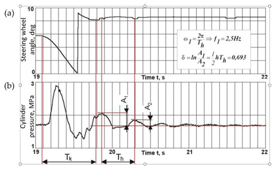
Figure 1.
Pressure pulsation in hydraulic actuator of the steering system as a response to steering wheel forcing action—(a) forcing signal and (b) response signal. Ts—time of steering wheel turn, and TFD—period of articulated frame oscillation.
Recognition of the snaking phenomenon required a vehicle stability investigation at top speed on a straight-line strip and, 125% of vehicle width over tire [7,17]. We investigated 20-ton loaders with a hydraulic steering system with mechanical feedback (5.5 revolution per full-frame turn), and with a hydraulic steering unit (hydraulic feedback) working in a load-sensing system (LS) with a hydraulic amplifier (3.2 revolutions per full frame turn). The results (Figure 2a) showed that during stable movement, lateral displacement exhibited sinusoidal change and could reach 20 cm. In a system with a higher gain (Figure 2b), drivers with lower experience could lose stability, and displacement would constantly grow, causing the driver to stop the vehicle.

Figure 2.
Example of driver lateral displacement during straight-line riding at 30 km/h speed—(a) hydraulic steering system with mechanical feedback and (b) hydraulic steering system with load-sensing system (LS) and hydraulic amplifier.
When riding, the length of the hydraulic actuators continuously changed (Figure 3) due to the driver constantly acting on the steering wheel. The steering wheel’s rotation as the driver reacted to the on-vehicle’s location, strongly depended on speed, driver experience, and type of hydraulic steering system, but typically during stable movements, steering wheel rotation did not exceed 20°, with an average frequency of 0.4 Hz [23]. According to Chaczaturow et al. [24], driver action caused driver lateral displacement or driver angular deviation from the strip axle. During straight-line car driving, angular deviation did not exceed 0.5° and the reason for driver action was mainly lateral driver displacement. Previous research [2] confirmed this and showed that driver perception and sensing were limited. During driving on a straight strip, humans do not sense a lateral displacement error of up to 0.1 m and a yaw deviation of up to 0.5°.
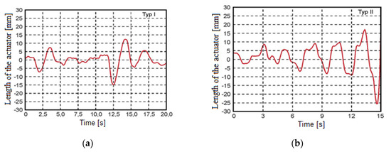
Figure 3.
Example of hydraulic actuator displacement during straight-line riding at 30 km/h speed—(a) hydraulic steering system with mechanical feedback and (b) hydraulic steering system with LS and hydraulic amplifier.
The values of the human sensing level of angular deviation during articulated vehicle riding permanently exceeded a frequency of about 0.4 Hz (Figure 4a). Deviations of the front frames achieved ±1°. Rear frame achieved a bigger deviation—of up to ±1.7°, due to a lower rear tire pressure and lateral stiffness. Frame turn in articulated joints did not typically exceed 1° (Figure 4b). As in articulated wheel loaders, the driver seat is typically placed above an articulated joint and connected to the rear frame, these deviations trigger driver action and activate the snacking phenomenon.

Figure 4.
Angular frame deviation during straight-line drive (a) and frame turn and angular deviation of front frame (b).
This phenomenon did not exist in vehicles with a steering system, based on the Ackermann principle. The design and work characteristics (positive caster angle) of such a system enable acting stabilizing torque [12], which straightens the leading wheel position. In articulated vehicles with hydraulic steering systems, stabilizing moments do not exist. All errors must be eliminated by the drivers, which have limited ability as their acting and feeling accuracy is about 0.5°.
Initial deviation is caused by limited driver accuracy during maneuvering and the driver sensing only one frame position; at the same time the second frame can be twisted in an articulated joint, which leads to yaw. After the driver closes directional valves in the hydraulic actuator chambers, residual pressure tension of up to 1 MPa can remain, due to friction in the actuator sealing. During riding, this pressure acts on pistons and causes additional frame turn, due to vibration.
According to Figure 4, the leading vehicle front-frame deviation preceded the rear frame yaw. Hence, the loader vehicle drivers led the part deviation with a time lag. This delayed reaction and increased lateral vehicle displacement and angular deviation. Moreover, hydraulic steering systems introduced an additional time lag, as a result of the mechanical and hydraulic characteristics of the system [2]. In hydraulic systems with mechanical feedback, this delay amounted to 0.45 s and in systems with LS and a hydraulic amplifier, it could amount to 0.35 s. Other authors [22] showed that to limit internal leakage, the rotary valve of the steering unit had a positive overlay, which caused a 2° dead zone and disturbed the steering system action. Finally, in articulated loaders, the driver reaction was permanently delayed and this caused the necessity of a permanently high level of activity from the driver.
In modified articulated loaders, the driver seat was in the front of the vehicle and was connected to the front frame. Thus according to Figure 4, the drivers felt a deviation earlier because the rear frame deviation was delayed and their reaction to the leading frame’s position could be quicker and provided better directional stability. To improve vehicle reaction, the steering system should be quicker, without LS, and a hydraulic amplifier. To verify this theory, study of a modified loader was conducted.
For the test, a direct hydraulic steering system without LS and amplification was used and the driver was moved to the front of the vehicle to heighten his sensing of yaw (Figure 5). The time lag, which is caused in such hydraulic systems through a pressure transmission in the pipeline, was about 0.05 s. During riding, the average steering wheel rotation was similar (a bit smaller), compared to other hydraulic systems, and its values were about 15°–20°. Driver and front frame yaw deviation were on the same level, at about 1°. However, an increase in low driver activity duration was observed (Figure 5b);—points 1 to 2 and 3 to 4, and the interval between interventions increased from 2.5 s to about 4 s. During low driver activity, steering wheel rotation was about 5°, and was probably caused by driver vibration and inertia during riding. Considering the dead zone in the rotary valve, these steering wheel rotations had no significant influence on the steering system operation. This was confirmed by the hydraulic actuator length measurements. This meant that better yaw sensing and a shorter time lag in the steering system could significantly improve the stability of articulated vehicles and enable a higher driving speed. However, the main problem was the absence of mechanisms that straighten the frame like in vehicles with an Ackermann-based steering system principle. Necessity of continuous correction of frame twist by the driver was the main limitation of the articulated vehicle speed. During riding with a higher speed, the driver sensing and acting ability could be too low and the vehicle could lose stability. In order to increase the articulated vehicle speed, it was necessary to introduce a driver-aid system correcting the frame twist. This should lower the driver effort and reduce driver activity to levels observed in vehicles with a steering system, based on the Ackermann principle.
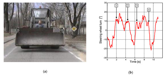
Figure 5.
View of the modified loader with driver before front axle and direct hydraulic steering system during straight-line test (a), and driver reactions during modified loader straight-line test at a speed 28 km/h (b).
3. Concept of Driver-Aid System
Vehicles (e.g., cars) with Ackermann-based steering systems due to their geometry and characteristics (positive caster angle), have the ability to stabilize vehicle direction. In contrast, the geometry of the steering system in articulated vehicles, makes the driver responsible for stabilizing the steering system. The driver’s perception limits the accuracy of vehicle heading, the directional stability of movement, and the top permissible speed. To improve the directional stability of the articulated tractors, the limited sensitivity of the human brain should be supported by the driver-aid system. Since the driver sensitivity of yaw deviation is limited to about 0.5° and this is the main cause of poor directional stability of articulated vehicles, the driver-aid system should straighten the frame and eliminate small frame twist that lead to growing deviations.
For this reason, the proposed system consists of a steering wheel rotation, a frame articulation sensor, and an additional hydraulic circuit for straightening the frame (Figure 6a). For the driver-aid system, we assumed that such a system should act only when the main steering system controlled by the driver was not operating (maneuver was not conducted), and that its flow should be as small as possible and not disturb the main steering system operations, in case of driver-aid system failure. Moreover, its energy consumption should be low and jerk accelerations should not be generated. Hence, the driver-aid system switched on an additional pump to straighten the frame when the steering system wheel sensor indicated that the frame twist was below 1°. It was assumed that such a situation corresponded to straight-line riding. The system should stop when the frame articulation sensor indicated frame straightening. Due to safety reasons, the flow in the driver-aid system was assumed to be 10% of the main steering system flow, considering the maximal steering wheel angular speed was 100 rpm, according to [25,26]. In the analyzed case, it was 10 dm3/min.
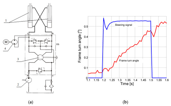
Figure 6.
Driver aid system—(a) diagram of hydraulic steering system with additional driver-aid system: 1—steering hydraulic actuator, 2—main pump, 3—hydraulic steering unit, and 4—additional pump with electric drive; and (b) frame turns as results of additional gear pump operation.
To verify the operation capability, the possibility of such system actions was investigated, considering a high moment of inertia of the rotated front and rear parts of the vehicle. For this reason, an additional hydraulic system powered with a 24V electric motor, 2.2 kW power, and 10 dm3/min pump flow was installed on 20-ton wheel loader, and the time domain characteristics were determined. The results (Figure 6b) showed that during 0.3 s of operation, the pump achieved almost nominal flow at 8 dm3/min, and the frame turned about 0.5°, a value comparable to the initial frame twist. This was a favorable result because it indicated a high speed of turn corrections almost without any time lag, and with a low power consumption at a small pump flow rate, and indicated the possibility to operate such systems.
4. Method
4.1. Vehicle Model
For evaluating the operational efficiency of such a system and estimating its main parameters, a 3D multi-body model simulation of an articulated vehicle as a steered vehicle was developed in the Adams 2014.0.1 (MSC Software Corporation, Newport Beach, CA, USA) software A collaboration co-simulation model of a driver and hydraulic steering system was developed in the Easy5 2015.0.1 Version 9.1.1 (MSC Software Corporation, Newport Beach, CA, USA) software. The assumed principle of the vehicle model is shown in Figure 7 and its parameters are presented in Table 1.

Figure 7.
Assumption for model of the articulated vehicle as a steered vehicle.

Table 1.
Parameters of the Articulated Vehicle Model.
4.2. Driver Model
Modeling human driver behavior is a well-known problem in automotive research. Many different models are used, including linear transfer function models, non-linear models, adaptive controllers, neural networks, and fuzzy logic controllers for modeling complex task performance, including acceleration, braking, and steering, with a driver in the loop. These models can be used to simulate human drivers when testing new vehicle designs and technology to verify developed solutions or concepts [27,28]. According to previous studies [13,29], low order models are often sufficient for many control tasks and are more reliable and easier to apply, because model parameters are relatively easy to identify and determine. The essential requirements of a model should include a time delay due to human processing and acting ability [28,30]. The time delay is strongly connected with driver concentration level, and depend, for example, on vehicle velocity and vehicle and strip width.
Vehicle steering models can use one or more feedback signals as input to the driver model including—lateral displacement, lateral velocity, lateral acceleration, yaw angle, yaw rate, yaw acceleration, roll angle, roll rate, roll acceleration, and other parameters, such as sound and vibration [13,24,26]. Driver behavior emerges from visual cues, motion effects, and tactile feedback.
During straight-line driving and vehicle stability investigation [24,31], the main signals for driver behaviors were lateral displacement and yaw angle (Figure 8)—and models with these inputs were sufficient. Considering the results from investigating the nonlinearity, reflecting time lag and limited driver sensing were introduced (Figure 9). The assumption for the model was that the driver always observed a point on the road. The observable point lay on the required vehicle trajectory at a distance of L from the driver. Distance L depends on vehicle velocity and curvature of trajectory. Any lateral or angular driver inclinations might cause the driver’s reaction.

Figure 8.
Diagram of steering control loop with driver input as lateral displacement and yaw angle.
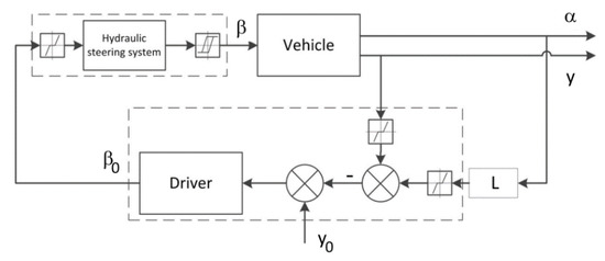
Figure 9.
Steering control loop with non-linearity in driver behavior.
Typically, driver behaviors are described as an anticipative model [24,31,32]. To obtain more credible results, both models were used. Due to the lateral driver displacement being below the driver perception level, according to our assumption, the anticipative driver behavior was described as (based only on angular displacement):
where, βD(s)—driver output signal; α(s)—driver input signal (yaw angle); αo(s) = 0—desired yaw angle; K—system gain; KD—derivative gain; KI—integral gain; and KP—proportional gain. The driver model parameters after tuning are shown in Table 2. In the inert model, the driver behavior was described as:
Table 2.
Parameter of Anticipative Driver Model.
The model parameters after tuning are shown in Table 3. The whole model developed in the Easy5 2015.0.1 Version 9.1.1 (MSC Software Corporation, Newport Beach, CA, USA) software of a vehicle control system is shown in Figure 10.
Table 3.
Parameter of the Inert Driver Model.

Figure 10.
Diagram of vehicle control system developed in the MSC.Easy5 software.
5. Results and Discussion
The goal of the simulation was to select the best driver model, then to verify the acting efficiency of the proposed driver-aid system and finally to investigate the possibility of increasing vehicle velocity. For these reasons, the simulation of straight-line riding with a speed of 30 km/h was made. To compare simulation results with experimental results, a simulation was conducted for both anticipative and inert driver models. Apart from the two driver positions, sitting at the front and above the articulated joint were taken into consideration. In the beginning, the linear model of drivers without a dead zone of sensing was used. For both driver models (anticipative and inert), the snacking phenomenon did not occur. The system was stable without any oscillation. After adding dead zones of driver perception, oscillation appeared in both models. This confirmed that limited driver perception was crucial for the occurrence of the snaking phenomenon. For these reasons, the non-linear driver model was used for the following simulation.
The conducted simulations confirmed the high quality of the used models and the coherence of the results. For the anticipative driver model, results for sitting at the front of the vehicle are shown together with long low driver activity periods (Figure 11a). The length of the hydraulic actuator changed by about ±15 mm. The lateral axle displacement reached 70 mm and the driver yaw angular deviation was about 0.65° (Figure 11b,c, respectively). The oscillation period was about 5.2 s. In the case of the driver sitting above the joint and connected with the rear frame, there was no low driver activity period (Figure 11d) and the length of the actuator changed by up to ±50 mm. The driver was constantly active and the oscillation period was about 4 s. This meant that driver effort was much higher. Despite this lateral axle, displacement reached 120 mm and the driver yaw angular deviation was about 1.45° (Figure 11e,f, respectively).

Figure 11.
Example of simulation for anticipative driver siting before front axle of vehicle—(a) hydraulic actuator displacement, (b) lateral displacement of front—1 and rear—2 axle, (c) yaw angular driver deviation, (d) hydraulic actuator displacement, (e) lateral displacement of front—1 and rear—2 axle, and (f) yaw angular driver deviation.
The simulation performed for the same assumption but with an inert driver model produced slightly different results. For a driver model sitting at the front of the vehicle, similar long low driver activity periods arose (Figure 12a), but the oscillation period was shorter, at about 4.5 s, and the hydraulic actuator length changed by about ±12 mm. The lateral axle displacement reached 51 mm and driver yaw angular deviation was about 0.52° (Figure 12b,c, respectively). In the case of the driver sitting above the joint and connected with the rear frame, there was no low driver activity period (Figure 12d) but the length of the hydraulic actuator changed by only up to ±10 mm. The oscillation period was shorter, at about 3.4 s. Despite this, the lateral axle displacement reached 170 mm and driver yaw angular deviation was about 2.3° (Figure 12e,f, respectively). Comparisons of experimental and simulated results showed that the inert model produced much better results. The period of oscillation and lateral displacement was reflected better. It was particularly visible in the simulation with the driver siting over the articulating joint and connected with the rear frame of vehicle. For these reasons, the inert model was selected as a better driver model for future simulations.

Figure 12.
Example of simulation for inert driver siting before front axle of vehicle—(a) hydraulic actuator displacement, (b) lateral displacement of front—1 axle and rear—2 axles, (c) yaw angular driver deviation, (d) hydraulic actuator displacement, (e) lateral displacement of front—1 axle and rear—2 axles, and (f) yaw angular driver deviation.
As the driver was sitting at the front of the vehicle in transport applications, such as articulated dump trucks and forwarders, and given the possibility of the speed increasing, it was crucial for these applications that the following simulation for higher vehicle velocity was made for this configuration. The results showed (Table 4) that the system could be stable up to 60 km/h but the driver must adapt their behavior. The period of oscillation caused by the snaking phenomenon for varied vehicle velocity was at similar level and the driver had to introduce corrections to the steering system at intervals of approximately 2 s. This indicated a demand for high driver concentration level and heavy physical effort during driving. The proposed driver-aid system should reduce this effort. To evaluate the efficiency of the driver-aid system, its operation was simulated. As an assumption for the simulation, straight-line driving was taken, with the driver triggering the aid system after introducing correction to the steering system. In automated mode, triggering should occur when the frame turn was below 0.5° and driver activity (steering wheel rate) was low. The aim of the aid system action was to prevent articulated frame twist, if it occurred, but the flow in the aid system was limited to 10% of the main steering system. The results of the simulation are shown in Figure 13. After 0.3 s, the frame twist was reduced to the demanded level and the yaw angle of the driver and vehicle was below 0.1°. The angular deviation did not increase and the lateral displacement increased very slowly, reaching the permissible 0.1 m (driver perception limit) in about 10 s. During this period, no driver action was needed. The vehicle movement was stable to aid the driver system’s operation and driver effort was significantly lowered—the interval between driver action increased by four to five times, meaning that lateral displacement was a major factor of driver reaction. Thus, the system’s behavior was similar to cars’ steering systems, and it allowed reaching higher speeds of vehicle motion with a lower level of driver effort and concentration.
Table 4.
Simulation results of high-speed driving with an inert driver model and a driver at the front of the vehicle.

Figure 13.
Example of simulation for inert driver model, siting at the front of the vehicle—(a) hydraulic actuator displacement, (b) lateral displacement of front (1) and rear (2) axle, and (c) yaw angular driver deviation.
6. Conclusions
The conducted research demonstrated that the low directional stability of articulated vehicles with hydraulic steering systems was mainly caused by limited driver perception in sensing angular yaw and the absence of mechanisms that straightened the twisted frame and prevented increasing lateral and angular deviation. In car steering systems, this task was performed by special steering knuckle geometry, which generate straightening torque. Hence, yaw was eliminated automatically and drivers had to mainly heave to react to lateral displacement. In the case of articulated vehicles, in contrast to cars, angular deviations were dominant due to the limited possibility to detect and eliminate them. Unnoticed yaw could reach 0.5° and unnoticed lateral displacement was 0.1 m. The conducted tests showed that a hydraulic steering system, especially one operating in an LS system, could introduce a time lag of up to 0.4 s. This lowered the overall steering system efficiency and the vehicle’s directional stability. The driver’s location significantly influenced movement stability. Driver placement at the front of the vehicle accelerated sensing of lateral and angular deviations from the path.
During the simulation, inert and anticipative driver models were used. The best results and higher simulation accuracy were obtained with the inert model.
Simulations showed that limitation of the snaking phenomenon during movement of articulated vehicles with the driver-aid system was possible. The principles of their operation were verified using simulations. A limited flow rate in the driver-aid system did not cause lateral jerk and acceleration, and high dynamic reactions.
The unique developed model of an articulated vehicle as a steered vehicle, exhibited full usefulness for such simulations and could be used in future work on developing the electronic control and the sensor systems necessary for stabilizing articulating vehicles.
The proposed system could increase the productivity of articulated equipment, due to a significant reduction in driver activity. It lowered the necessary driver effort and concentration level. It, thus, enabled the development of higher travel speed during operations. As was mentioned above, a vehicle’s velocity is crucial for its productivity and operation efficiency. The proposed system could also be used to improve the stability of robotized articulated vehicles—one of the main development direction of modern mining equipment. In automated or robotized equipment, it is strongly recommended to measure the frame twist and connect sensors of deviation to the front frame of vehicle.
This paper only presented the concept and preliminary simulations of the new system. The simulations showed that it is possible to increase directional stability of the articulated vehicles. The results should be verified using wider simulations with different scenarios (on various types of terrain and with different slopes). Before the implementation of such a system on vehicles, risk assessments should be conducted and the implementation possibility of additional safety systems for the driver should be taken into consideration.
Author Contributions
Conceptualization: M.J.Ł.; Methodology: M.J.Ł.; Software: M.J.Ł. and A.R.; Validation: A.R., Formal analysis: M.J.Ł. and A.R.; Investigation: M.J.Ł. and A.R.; Resources: M.J.Ł.; Data curation: A.R.; Writing—original draft preparation: M.J.Ł.; Writing—review and editing: M.J.Ł. and A.R.; Visualization: M.J.Ł. and A.R.; Supervision: M.J.Ł.; Project administration: M.J.Ł. and A.R.; Funding acquisition: M.J.Ł. All authors have read and agreed to the published version of the manuscript.
Funding
This research was funded by Military University of Technology under project number 22—758 “Badania konstrukcji maszyn i innowacyjnych technologii wytwarzania oraz systemów Bezzałogowych Platform Lądowych”.
Conflicts of Interest
The authors declare no conflict of interest.
References
- Petraska, A.; Cizuniene, K.; Jarasuniene, A.; Maruschak, P.; Prentkovskis, O. Algorithm for the assessment of heavyweight and oversize cargo transportation routes. J. Bus. Econ. Manag. 2017, 18, 1098–1114. [Google Scholar] [CrossRef][Green Version]
- Lopatka, M.J.; Muszynski, T. Research of the snaking phenomenon to improve directional stability of remote controlled articulated wheel tool-carrier. In Proceedings of the 20th International Symposium on Automation and Robootics Construction (ISARC), Technische Universiteit Eindhoven (TU/e), Eindhoven, The Netherlands, 21–25 September 2003; pp. 95–101. [Google Scholar]
- Meng, Q.; Gao, L.; Xie, H.; Dou, F. Analysis of the dynamic modeling method of articulated vehicles. J. Eng. Sci. Technol. Rev. 2017, 10, 18–27. [Google Scholar] [CrossRef]
- Dzyura, V.O.; Maruschak, P.O.; Zakiev, I.M.; Sorochak, A.P. Analysis of inner surface roughness parameters of load-carrying and support elements of mechanical systems. Int. J. Eng. Trans. B Appl. 2017, 30, 1170–1175. [Google Scholar]
- Maruschak, P.O.; Panin, S.V.; Zakiev, I.M.; Poltaranin, M.A.; Sotnikov, A.I. Scale levels of damage to the raceway of a spherical roller bering. Eng. Fail. Anal. 2016, 59, 69–78. [Google Scholar] [CrossRef]
- Alshaer, B.J.; Darabseh, T.T.; Alhanouti, M.A. Path planning, modeling and simulation of an autonomous articulated heavy construction machine performing a loading cycle. Appl. Math. Model. 2013, 37, 5315–5325. [Google Scholar] [CrossRef]
- ISO. Standard ISO 5010:2007-06 (E): Earth-Moving Machinery—Rubber-Tyred Machines—Steering Requirements; ISO: Geneva, Switzerland, 2007. [Google Scholar]
- Malinowskij, E.J.; Gajcgori, M.M. Dinamika Samochodnych Maszin s Szarnirnoj Ramoj; Maszinostrojenie: Moscow, Russia, 1974. (In Russian) [Google Scholar]
- Crolla, D.A.; Horton, D.N.L. The steering behaviour of articulated body steer vehicles. In Proceedings of the I. Mech. E. Conference on Road Vehicle Handling, Loughborough, UK, 22–24 May 1983; Mechanical Engineering Publications: London, UK, 1983. [Google Scholar]
- Horton, D.N.L.; Crolla, D.A. Theoretical analysis of the steering behaviour of articulated frame steer vehicles. Veh. Syst. Dyn. 1986, 15, 211–234. [Google Scholar] [CrossRef]
- He, Y.; Khajepour, A.; McPhee, J.; Wang, X. Dynamic modelling and stability analysis of articulated frame steer vehicles. Int. J. Heavy Veh. Syst. 2005, 12, 28–59. [Google Scholar] [CrossRef]
- Wong, J.Y. Theory of Ground Vehicles; John Wiley & Sons, Inc.: Toronto, ON, Canada, 1998. [Google Scholar]
- Azad, N.L.; McPhee, J.; Khajepour, A. Off-road lateral stability analysis of an articulated steer vehicle with a rear-mounted load. Int. J. Veh. Syst. Model. Test. 2005, 1, 106–130. [Google Scholar] [CrossRef]
- Rehnberg, A. Vehicle Dynamic Analysis of Wheel Loader with Suspended Axles. Ph.D. Thesis, KTH, School of Engineering Sciences (SCI), Aeronautical and Vehicle Engineering, Vehicle Dynamics, Stockholm, Sweden, 2008. [Google Scholar]
- Rehnberg, A.; Drugge, L.; Stensson Trigell, A. Snaking stability of articulated frame steer vehicles with axle suspension. Int. J. Heavy Veh. Syst. 2010, 167, 119–138. [Google Scholar] [CrossRef]
- Rehnberg, A.; Edrén, J.; Eriksson, M.; Drugge, L.; Stensson Trigell, A. Scale model investigation of the snaking and folding stability of an articulated frame steer vehicle. Int. J. Veh. Syst. Model. Test. 2011, 6, 126–144. [Google Scholar] [CrossRef]
- ISO. Standard PN-EN 12643:2000: Earthmoving Machines, Rubber Wheeled Machines: Requirements Concerning the Steering System; ISO: Geneva, Switzerland, 2000. [Google Scholar]
- Dudzinski, P.; Skurjat, A. Directional dynamics problems of an articulated frame steer wheeled vehicles. J. KONES Powertr. Transp. 2012, 19, 89–98. [Google Scholar] [CrossRef]
- Zardin, B.; Borghi, M.; Gherardini, F.; Zanasi, N. Modeling and simulation of a hydrostatic steering system for agricultural tractors. Energies 2018, 11, 230. [Google Scholar] [CrossRef]
- Daher, N.; Ivantysynova, M. A virtual yaw rate sensor for articulated vehicles featuring novel electro-hydraulic steer-by-wire technology. Control Eng. Pract. 2014, 30, 45–54. [Google Scholar] [CrossRef]
- Daher, N.; Ivantysynova, M. Yaw stability control of articulated frame off-highway vehicles via displacement controlled steer-by-wire. Control Eng. Pract. 2015, 45, 46–53. [Google Scholar] [CrossRef]
- Lopatka, M.J. Investigation of Snaking Phenomenon Limitations in Articulated Combat Equipment; Grant Report KBN nr 0T00B01921; Military University of Technology: Warsaw, Poland, 2004. [Google Scholar]
- Lopatka, M.J.; Muszynski, T.; Przychodzien, T. Research of high speed articulated wheel tool-carrier steering systems. In Proceedings of the 9th European Regional Conference of The International Society of Terrain-Vehicle Systems (ISTVS), Harper Adams University College, Newport, UK, 8–11 September 2003; pp. 261–272. [Google Scholar]
- Chaczaturow, A.A.; Afanasjew, W.L.; Wasiliew, W.S.; Goldin, G.W.; Dodonow, B.M.; Żigariew, W.P.; Kołcow, W.I.; Jurik, W.S.; Jakobliew, E.I. Dinamika Sistemy Doroga-Szina-Awtomobil-Woditiel; Maszinostrojenie: Moscow, Russia, 1976. (In Russian) [Google Scholar]
- Danfoss. Hydrostatic Steering Components: Hydrostatic and Hydromechanical Steering Systems HK.20.B1.02; Danfoss: Nordborg, Denmark, 2019. [Google Scholar]
- Eaton. Steering Control Units and Torque Generators: Char-Lynn Power Steering No 11-872; Eaton Corporation: Dublin, Ireland, 2002. [Google Scholar]
- Delice, I.I.; Ertugrul, S. Inteligent modeling of human driver: A survey. In Proceedings of the IEEE 2007 Intelligent Vehicles Symposium, Istanbul, Turkey, 13–15 August 2007; pp. 648–651. [Google Scholar]
- MacAdam, C.C. Understanding and modeling the human driver. Veh. Syst. Dyn. 2003, 40, 101–134. [Google Scholar] [CrossRef]
- Brito Palma, L.; Vieira Coito, F.; Sousa Gil, P. Low orders models for human controller-mouse interface. In Proceedings of the IEEE 2012 16th International Conference on Intelligent Engineering Systems (INES), Lisbon, Portugal, 13–15 June 2012; pp. 515–520. [Google Scholar]
- Kesting, A.; Treiber, M. How reaction time, update time, and adaptation time influence the stability of traffic flow. Comput. Aided Civil Infrastruct. Eng. 2008, 23, 125–137. [Google Scholar] [CrossRef]
- Andrzejewski, R.; Awrejcewicz, J. Nonlinear Dynamics of a Wheeled Vehicle; Springer: New York, NY, USA, 2005. [Google Scholar]
- Chen, X.; Li, R.; Xie, W.; Shi, Q. Stabilization of traffic flow based on multi-anticipative intelligent driver model. In Proceedings of the 12th International IEEE Conference on Intelligent Transportation Systems 2009, St. Louis, MO, USA, 4–7 October 2009. [Google Scholar]


© 2020 by the authors. Licensee MDPI, Basel, Switzerland. This article is an open access article distributed under the terms and conditions of the Creative Commons Attribution (CC BY) license (http://creativecommons.org/licenses/by/4.0/).