Abstract
As a kind of common phenomenon in practical engineering, misalignment error considerably changes the working performance of bearing. However, it has rarely attracted attention in the study of duplex angular contact ball bearings (DACBBs). To evaluate the influence of misalignment on DACBB, an analytical model of DACBB considering combined loads and angular misalignment is established for back-to-back, face-to-face, and tandem configurations. According to the geometrical relationship inside the bearing, the deformations caused by external load and angular misalignment are systematically analyzed. On this basis, the effects of external load, axial preload, and angular misalignment on the displacement, maximum contact load, contact load distribution, contact angle, and fatigue life of DACBB are analyzed. The results demonstrate the high dependence of the contact load and contact angle on the above factors. Angular misalignment causes the fluctuation of contact load and contact angle distributions along the azimuth angle of a rolling ball. Nonlinear relationships between fatigue life of DACBB, angular misalignment, and axial preload are obtained. The occurrence of angular misalignment considerably decreases the fatigue life of DACBB. The results suggest the necessity of angular misalignment analysis for DACBB.
1. Introduction
As one of the most important supporting components in transmission systems, angular contact ball bearings (ACBBs) are widely used in numerous rotating machinery systems for their high reliability and high precision. In such applications, a single row ACBB is often assembled into a duplex angular contact ball bearing (DACBB) to improve the stability of the bearing-rotor system. DACBB shows certain advantages over ACBB in terms of rigidity, rotating accuracy, and load-carrying capacity [1]. Therefore, it has been widely adopted in automotive wheels, compressors, turbines, centrifugal pumps, and machine tool spindles [2,3,4].
In the early study of rolling bearings, Jones et al. [5,6,7] established the classical analytical model for rolling bearings. Subsequently, with deepening research in rolling bearings, lots of researchers [8,9,10,11,12,13] became devoted to improving the classical theory to deal with various problems in bearings applications. Recently, some new works have been published to the study the influences of various structure parameters and load conditions on the operating performance of ACBBs [14,15,16,17]. Liu et al. [18] developed a new analytical method for combine loaded ACBB by considering the axial preload and the variation of contact angle to estimate the internal load distribution and stiffness of ACBB. Clearance is an important parameter influencing the performance of bearings, and Zmarzly [19] presented research to evaluate the effect of radial clearance on the basic exploitation of bearings, such as vibration level. As one of the most common errors in practical engineering, ring misalignment error also attracted widespread attention from researchers [20,21,22]. Previous studies demonstrated that ring misalignment error considerably influences the characteristics of ACBBs, such as load distribution and fatigue life, and further determines the performance of rotating machinery. Bae et al. [23] calculated the fatigue life of ACBB according to de Mul’s model and the basic reference rating life in Standard ISO 1628 of International Standards Organization ISO. The research demonstrated that the load distribution and fatigue life of ACBB were significantly influenced by the angular misalignment. Xu et al. [24] found that the misalignment error would reduce the bearing life and even cause bearing failure. Zhang and Ye [25,26] studied the contact angle and local stiffness distribution of ACBB by introducing the influence of misalignment. Considering the angular misalignment, Tong et al. [27] investigated the running torque of ACBB under constant force and constant displacement preload. Oktaviana et al. [28] analyzed the skidding condition of ACBB under combined load and angular misalignment. The results shown that the angular misalignment could increase the bearing skidding. Liao et al. [29] proposed an analytical method for ACBB by considering angular misalignment. The misalignment and the deformations generated in the axial and radial directions were taken as three knowns in the analysis. Considering the influence of angular misalignment, Xiong et al. [30] established a mathematical model of ACBB and studied the stiffness, contact angle, contact stress, and spin-to-roll ratio of ACBB. Zhang et al. [31] evaluated the influences of combined angular misalignment and axial preload on the fatigue life of ACBB and the shaft-bearing systems. Zhang et al. [32] presented an improved quasi-static model of ACBB and discussed the effect of angular misalignment on the service characteristics of ACBB and the natural frequency of rotor systems. The results demonstrated that angular misalignment considerably changes the contact state and stiffness of ACBB, and further influences the performance of the bearing-rotor system. In addition, in the study of roller and self-aligning bearings, the misalignment phenomenon has also attracted much attention from scholars [33,34,35,36,37,38]. Xing et al. [34] presented a theoretical model for spherical roller bearings by considering the angular and centroidal misalignments of bearing rings. Geng et al. [35] proposed a five degree-of freedom quasi-static model for double-row self-aligning ball bearings and investigated the effect of angular misalignment on the dynamic characteristic of the bearing. Tong and Hong [36,37,38] completed a series works on the tapered roller bearings subjected to angular misalignment. Their studies suggested that angular misalignment greatly influences the fatigue life, contact state, running torque, and stiffness of tapered roller bearings.
Up to now, only a few articles on double-row or combined ball bearings have been reported. Bercea et al. [39] developed a unified analytical model for various types of double-row bearings, such as tapered, spherical, cylindrical roller, and angular contact ball bearings. Based on the efforts of Lim and Singh [40] and Royston and Basdogan [41], Gunduz [42] proposed a comprehensive mathematical model of double row angular contact ball bearings for back-to-back, face-to-face, and tandem configurations. Double row bearings were considered as an integrated unit, and the detailed stiffness expression of DACBB was also formulated. Zhang et al. [43] developed a new iterative algorithm to evaluate the preload and stiffness coefficients of combined ACBBs. Yang et al. [44] estimated the performance of the spindle supported by the ACBB with different configurations. Kogan and Petersen [45,46] established a dynamic model for double row ball bearings with different defects. Deng et al. [47] established a dynamic stiffness model of DACBB with back-to-back configuration according to the dynamic analysis of the bearing. On this basis, the influences of bearing structural and load condition on the radial, axial, and angular stiffness coefficients of DACBB were analyzed. However, the dynamic analysis of bearing was not clearly given. Xie et al. [48] established a quasi-static model of DACBB to study the effects of speed, external load, and preload on the characteristics of DACBB. Based on Jones theory, Lin and Jiang [49] proposed a five degree-of-freedom quasi-static model for preloaded DACBB. The stiffness of DACCB with three configurations was simulated under different rotating speeds and unloaded contact angles. Subsequently, they further investigated the dynamic performance of the bearing-rotor system supported by the DACBB with tandem configuration [50].
From the above literature survey, it can be found that, unlike single-row ACBB that has been extensively studied, only a few studies on DACBB have been published. Therefore, the theoretical research on the DACBB should be further enriched. Furthermore, most previous researches related to ring misalignment are mainly aimed at roller bearing, self-aligning bearing and single row angular contact ball bearing, very few studies on the ring misalignment phenomenon in the DACBB have been reported. Tong and Hong [51] carried out some meaningful study and proposed a quasi-static mechanical model for DACBB according to de Mul’s theory [7]. The stiffness and fatigue life of DACBB under angular misalignment were studied. Generally, owing to main shaft deflection, mounting error, and geometric inaccuracy, DACBB commonly runs with angular misalignment [35,36,37,52]. In order to control the magnitude of angular misalignment of inner ring, it is necessary to improve the machining and assembly accuracy of bearing, shaft, and bearing seat. This would lead to a sharp increase of manufacturing costs. In addition, the ignorance of misalignment phenomenon in the study of DACBB may lead to large deviation between actual performance and simulated results of DACBB. Therefore, it is necessary to study the DACBB under misalignment operating condition in theory so as to meet the urgent requirements of engineering. Moreover, it is also found that most previous researches of DACBB mainly aimed at the bearing stiffness, while bearing displacement, contact load, and contact angle are rarely involved.
To address the aforementioned issues, this paper presented a three degree-of-freedom static model for preloaded DACBB. The misalignment angle of inner ring, external radial and axial loads are regard as the input condition in the analysis. According to the analysis of the deformation inside the bearing, the analytical approach of DACBB is established for back-to-back or ‘O’, face-to-face or ‘X’, and tandem configurations. Subsequently, taking the DACBB arranged in back-to-back configuration as the research object, the radial/axial displacement, contact load and contact angle of DACBB are systematically studied under different angular misalignments, axial preloads and combined external loads. Finally, based on the theory presented by Lundberg and Palmgren [53], the fatigue life of DACBB is also evaluated under various axial preloads, external loads, and misalignment angles.
2. Analytical Model of DACBB
In applications, ACBB is usually assembled into DACBB to improve the rigidity and load carrying capacity. In order to meet different working conditions, DACBB is often arranged in three configurations according to the organization of rolling element, as shown in Figure 1: (1) back-to-back or ‘O’ configuration (Figure 1a); (2): face-to-face or ‘X’ configuration (Figure 1b); (3) tandem or series configuration (Figure 1c). Generally, inner ring misalignment can be divided into two cases: centroidal misalignment and angular misalignment [33,52]. However, as an important supporting component on the shaft, DACBB unavoidably runs in angular misalignment operating condition [35].
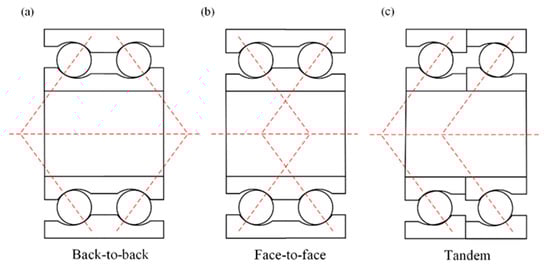
Figure 1.
Three configurations of DACBB: (a) back-to-back (DB) or ‘O’ arrangement; (b) face-to-face (DF) or ‘X’ arrangement; (c) tandem (DT) or series arrangement.
In practical applications, inner ring of bearing can easily tilt an angle relative to the outer ring owing to the deflection of main shaft. And the angular misalignment is a kind of typical misalignment error in the bearing-rotor systems [32]. Therefore, only the case of angular misalignment error is considered in this paper. It is defined as the tilt angle between inner and outer ring, as illustrated in Figure 2.
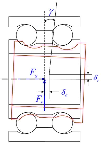
Figure 2.
Angular misalignment of DACBB.
2.1. Assumptions
In actual situation, misalignment angle of inner ring may be non-constant because of time-varying external load [36]. If the non-constant angular misalignment is considered, the study will be very difficult. Hence, in the analysis of current work, angular misalignment is considered as a constant value. Furthermore, in general, both inner and outer raceways of bearing may move and deflect under external load [7,42]. However, in order to simplify the analysis, it is sufficient to consider the relative displacement between the inner and outer rings. As a result, the bearing can be conveniently analyzed by assuming that the outer ring is fixed in the space and the inner ring displaces under the external load. And the problem then is to establish the equilibrium of inner ring. Meanwhile, this simplified approach is also adopted by lots of researchers [7,42,53]. Moreover, to establish an analytical model of DACBB, the following assumptions should also be made:
- The contact between rolling elements and raceways satisfies the Hertzian point contact.
- The rolling elements are evenly distributed.
- Each row of DACBB has the same structural parameter and operating condition.
- The inner and outer groove centers and ball center are collinear even though the inner ring of DACBB tilts a small angle relative to the outer ring.
- The centrifugal effect of rolling element is ignored in the analysis.
2.2. Analysis of Internal Deformation of DACBB
A cylindrical system , , with its origin in the geometrical center of DACBB is introduced in Figure 3. The z-axis is the bearing rotational axis, points to the radial direction of bearing, represents the azimuth angle of ball. The inner ring of DACBB is loaded externally by the load vector . and represent the external radial and axial loads, respectively. Angular misalignment between inner and outer rings is represented by the angle . As a result, two corresponding translational displacements of the bearing inner ring will be generated at the same origin. and denote the radial and axial displacements of inner ring, respectively. Meanwhile, the bearing will also produce an induced moment load . As shown in Figure 3b, and are the inner ring groove curvature centers of the left and the right rows of DACBB, respectively. According to the assumption in Section 2.1, only the inner ring groove curvature centers and move accordingly when the inner ring displaces. As a result, local displacement and contact load are generated, as shown in Figure 3b. Therefore, and are taking as the reference points in the following analysis. When the DACBB is subjected to combined external loads and angular misalignment, the local radial and axial displacements at reference points is
where and are the local radial and axial displacements, respectively. The subscript denotes the bearing rows, and represent the left and right row of DACBB, respectively. Meanwhile, at the reference points, the corresponding local contact load is generated
where and are the radial and axial contact loads between ball and raceway, respectively. Moreover, the centers of rolling ball of each row will also move to the new positions.
where and are the radial and axial displacements of ball center, respectively.
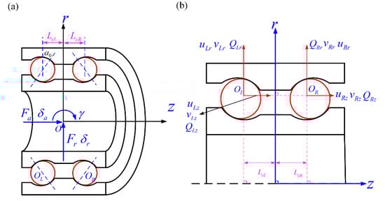
Figure 3.
Loads and displacements of DACBB. (a) external loads and displacements of inner ring; (b) local loads and displacements.
To calculate the internal deformation of each row of DACBB, deformations caused by the angular misalignment are firstly analyzed. As shown in Figure 4, and are the projection points of and on the bearing rotating axis, respectively. is the azimuth angle of ball. When the inner ring tilts relative to the outer ring. Accordingly, r-axis and z-axis will rotate to rT-axis and zT-axis, respectively. and will also rotate to and . As described in Figure 4, it is observed that the rotation of leads to the additional radial displacements of and . Because the rotating angle is usually small, the radial displacements of and can be approximately represented by and . Therefore, the additional radial displacements of and at the azimuth angle can be calculated by
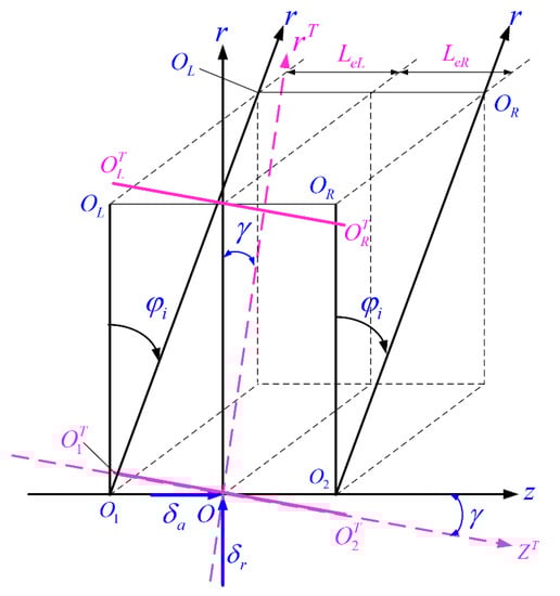
Figure 4.
Deformations of each row of DACBB.
Therefore, at different azimuth positions, the additional radial displacements of and caused by angular misalignment is
where , is used to adjust the sign of the radial displacements of the left and the right row.
where is the axial displacement between and and bearing geometrical center , which is
where is the axial distance between the geometric center of DACBB and bearing one row, is the unloaded contact angle, is the radius of inner ring groove. depends on the configuration of DACBB, which is
Similarly, as seen in Figure 4, the rotation of and also leads to additional axial displacements of and
where is the distance between the inner ring groove curvature center and z-axis, which is
where is the pitch diameter of DACBB.
Moreover, the radial and axial displacements of and caused by the external radial and axial load should also be considered. When the inner ring center of DACBB displaces the displacement , the reference points and will accordingly generate the local radial displacements. The local radial displacements of and at different azimuth position can be determined by
Similarly, for each row of DACBB, when the inner ring of DACBB is loaded by pure axial load, the reference points of DACBB at different azimuth positions have the same displacement . Therefore, the axial displacements of and caused by external axial load can be determined by
According to the aforementioned analysis, the total radial and axial displacements of and can be formulated as below:
As seen in Figure 5, the internal positions and displacements of ball center and reference points are illustrated under external load. According to the assumption in Section 2.1, the inner and outer ring groove curvature centers and ball centers are always collinear under angular misalignment condition. Therefore, the actual contact deformation between ball and raceway can be calculated. For the sake of generality, the clearance between ball and raceway is considered in current study. The initial distances between the center of ball and the center of inner/outer ring groove are
where and respectively denote the clearances between ball and inner/outer raceway. According to the geometrical relations shown in Figure 5, the actual distance between inner and outer ring groove centers is
where is a parameter related to the configuration of DACBB, which is expressed by:
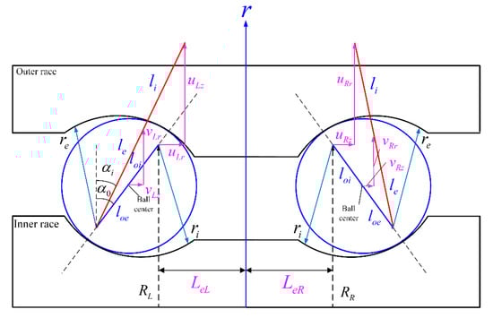
Figure 5.
Positions and displacements of the centers of ball and inner ring groove.
Meanwhile, DACBB is usually mounted on the shaft by preload, hence, the axial deformation caused by axial preload is considered, which ca be calculated by Equations (18) and (19)
where is axial preload, is the contact stiffness coefficient. Equation (18) can be solved by the Newton–Raphson method. Then, the axial deformation can be calculated. So, the Equation (16) is revised as:
Then, the total contact deformation between ball and raceway is:
Furthermore, it should be noted that the actual contact angle is not constant, but depends on the operating condition of DACBB. According to the geometrical relationship shown in Figure 5, the actual contact angle can be determined by:
or
2.3. Equilibrium Equation of DACBB
According to Hertzian contact theory, the contact load between ball and raceway is determined by:
Based on the Newton’s third low, the reaction forces that the ball applied to the inner ring can be decomposed in the directions of radial and axial:
where and represent the radial and axial components of contact load between ball and raceway, respectively. Then summing all the radial and axial components of contact load at different azimuth position of ball, the equilibrium equation of DACBB can be established as
Moreover, the contact load between ball and raceway will produce an induced moment load to balance the effect of angular misalignment. The induced moment load is expressed as follow
where is
It should be noted that the Equations (25) and (26) must satisfy the assumption that all the rolling balls of DACBB participate in the load transfer. However, in many situations, not all rolling balls inside the bearing are in contact with the raceway. In fact, when the external radial load and angular misalignment are very large or the axial preload is small, some rolling balls will be no longer constrained by the bearing inner ring [53]. This phenomenon will destroy the assumption of Equations (25) and (26). So, the rolling balls those do not participate in the load transfer should be excluded in the actual simulation. Evidently, as shown in Equation (21), if the contact deformation satisfies the relationship , ball and inner raceway will be in the critical or separate contact state, and the contact load will equal to zero. Therefore, the criteria for judging the contact state between ball and raceway is
Therefore, the Equations (25) and (26) should be modified as
where
where represents the number of inactive rolling balls, which is defined as the rolling ball that do not contact with the raceway. The above equilibrium equations are nonlinear. Therefore, Newton-Raphson iteration algorithm is adopted to solve the equations. In current simulation, the external radial and axial loads and , and angular misalignment are known. Therefore, there are only two unknowns ( and ) should be determined. Once the unknown radial and axial displacements are obtained, the contact load between rolling ball and raceway can be calculated according to Equation (23). Meanwhile, the fundamental calculation process is illustrated in Figure 6.
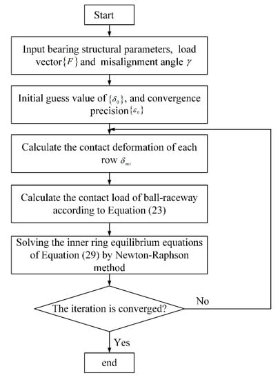
Figure 6.
The fundamental computational flow of proposed model.
3. Theoretical Fatigue Life of DACBB
Fatigue life theory of rolling bearings was firstly presented by Lundberg and Palmgren, and gradually accepted by the world’s major bearing manufacturers and the Standard ISO 281 [53]. This theory should be given priority in the case that the contact load distribution can be accurately obtained [1,2,4,53]. According to this theory, the fatigue life of DACBB is
where is a factor introduced to adjust the fatigue life of bearing, which is 1.3 according to Luo’s work [1]. represents the fatigue life of each row of DACBB, which is expressed by
where is the basic rating life of inner and outer raceway, which can be determined by
where is the equivalent contact load related to the actual load distribution. is the basic rating dynamic load, which is formulated by [53]
where and are the coefficient of inner or outer raceway groove coverture, respectively. And , , The equivalent contact loads of inner and outer ring are formulated by
In the above formula, the contact load between ball and inner/outer raceway can be determined by Equation (23).
4. Results and Discussions
Contact load distribution is an important factor reflecting the performance of rolling bearings. In order to verify the presented model of DACBB for calculating the contact load distribution, a comparison of contact load distribution between the current work and literature of Luo [1] is conducted under the same condition. In the comparison, DACBB is loaded by the combined external loads and moment load. The radial and axial loads are both 1000 N, the moment load is 10,000 Nmm. Meanwhile, DACBB is loaded by the axial preload of 580 N. The calculation results are shown in Table 1. From the results shown in Table 1, it can be observed that the contact load of current work shows the good agreement with the literature of Luo [1]. The agreement verifies the proposed model for calculating the contact load distribution of DACBB.

Table 1.
Results of current work and literature of Luo [1].
In general, studying the operating performance of rolling bearings is often based on two boundary conditions: (1) external load vector is known and the corresponding displacement vector should be solved according to the equilibrium equations, and (2) bearing displacement vector is known and the corresponding load vector should be determined [27]. However, the situation that arises frequently is that the rolling bearing is subjected to combined external loads and angular misalignment [33]. Misalignment effect is inevitable in the application of rolling bearings due to various reasons. Therefore, in this paper, the effect of angular misalignment is considered to extend the mechanical model of DACBB. Furthermore, the characteristics of DACBB such as radial/axial displacement, contact load, actual contact angle, and fatigue life under different conditions are evaluated. The type of angular contact ball bearing used for simulation is 7010 AC/DB. The basic structural parameters are shown in Table 2. Meanwhile, it should be noted that the study object of the whole article is the DACBB with back-to-back arrangement.
Table 2.
Structural parameters of ACBB 7010 AC/DB.
4.1. Displacement of DACBB
When the DACBB is loaded by the external loads, the center of DACBB will deviate from its original position. Therefore, in this section, the influences of external loads and axial preload on the radial and axial displacements of DACBB are evaluated.
Figure 7 shows the radial and axial displacements of DACBB under different external radial/axial loads and axial preloads. The angular misalignment of inner ring is ignored. As shown in Figure 7a,b, the influences of external radial load and axial preload on the radial and axial displacements of DACBB are illustrated. The external axial load is 3000 N, and the axial preload is changing from 100 N to 600 N. It can be observed that, with the increase of radial load, radial displacement of DACBB gradually increases, and the radial displacement is almost linearly related to the external radial load. However, with the growth of axial preload, the radial displacement of DACBB tends to be decreased. Meanwhile, it is also found that, under lower external radial load, the influence of axial preload on the radial displacement is not significant. However, as the external radial load gradually increases, the radial displacement obviously decreases with the increase of axial preload. Moreover, as described in Figure 7b, axial displacement of DACBB shows the opposite tendency compared to the result illustrated in the Figure 7a. Axial displacement significantly decreases when the external radial load increases. Similarly, the axial displacement of DACBB is also obviously dependent on the axial preload. With the increase of axial preload, axial displacement of DACBB shows the decreasing trend.
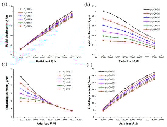
Figure 7.
Displacements of DACBB under different external loads and axial preloads : (a) radial displacement versus external radial load; (b) axial displacement versus external radial load; (c) radial displacement versus external axial load; (d) axial displacement versus external axial load.
Figure 7c,d describes the dependence of radial and axial displacements of DACBB on the axial preload and external axial load . The external radial load applied on the DACBB is 3000 N. As shown in Figure 7c, under different the axial loads and axial preloads, the variation of radial displacement of DACBB is different from that shown in Figure 7a. With the increase of external axial load, the radial displacement of DACBB gradually decreases. Meanwhile, it is also found that, under lower axial load, the radial displacement of DACBB is more sensitive to the axial preload than that under higher axial load. When the DACBB is loaded by lower axial load, radial displacement of DACBB significantly decreases with the increase of axial preload. However, as the axial load increases, the decreasing tendency of radial displacement tends to be reduced, and finally radial displacement becomes almost independent on the axial preload when the axial load exceeds 5000 N. In the same range of axial load, under lower axial preload, the radial displacement of DACBB is more sensitive to the applied axial load than that under higher axial preload. Furthermore, as shown in Figure 7d, with the increase of external axial load, the axial displacement of DACBB increases evidently. The influence of axial preload on the axial displacement of DACBB is the same as that shown in Figure 7b.
4.2. Maximum Contact Load of DACBB
Figure 8 illustrates the maximum contact loads of the left and the right rows of DACBB under combined loads. The external axial load and axial preload are 1500 N and 300 N, respectively. Figure 8a shows the maximum contact load of the left row of DACBB. It is clearly seen that the maximum contact load increases with the increase of external radial load. Meanwhile, as angular misalignment gradually increases, the maximum contact load tends to be sharply increased. For the maximum contact load of the right row, as described in Figure 8b, the variation of the maximum contact load shows the opposite tendency compared to that of the left row. As the external radial load increases, the maximum contact load tends to be decreased. Similarly, the maximum contact load of the right row also increases with the increase of misalignment angle. Relatively speaking, the effect of angular misalignment on the maximum contact load is more significant than that of radial load.
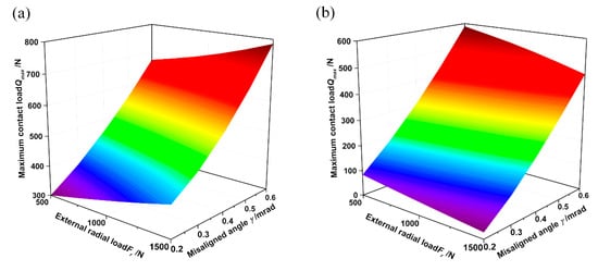
Figure 8.
Variation of maximum contact load under various radial loads and angular misalignments: (a) the left row of DACBB; (b) the right row of DACBB.
Figure 9 describes the dependence of the maximum contact load of the left and the right rows of DACBB on the axial preload and angular misalignment. The external radial and axial loads are both 1500 N. From the results shown in the Figure 9, it can be found that the maximum contact loads of the left and the right rows of DACBB both increase with the increase of the axial preload. The impact of angular misalignment on the maximum contact load of DACBB is the same as that shown in Figure 8. Meanwhile, compared to the axial preload, angular misalignment has a greater influence on the maximum contact load.
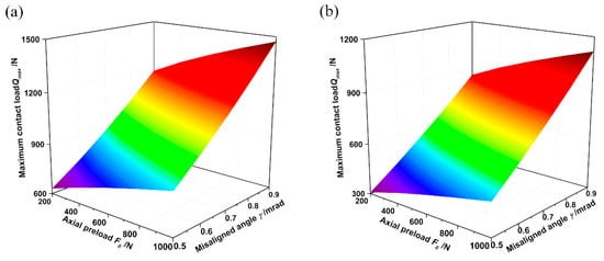
Figure 9.
Variation of maximum contact load under various axial preloads and angular misalignments: (a) the left row of DACBB; (b) the right row of DACBB.
4.3. Contact Load Distribution of DACBB
Contact load distribution is very important to analyze the characteristic of rolling bearings. The study of fatigue life, contact stress, frictional torque and energy loss of rolling bearings greatly depends on the contact load distribution. Therefore, in this section, contact load distribution of DACBB is evaluated under different working conditions.
Figure 10 shows the effect of axial preload on the contact load distribution of the left and the right rows of DACBB under combined external loads. The misaligned angle of inner ring is 0.2 mrad. The external radial and axial loads are 550 N and 500 N, respectively. From Figure 10, it can be seen that contact load distribution of DACBB is closely related to the axial preload. With the increase of axial preload, the contact load of the left and the right rows of DACCBB increase. Meanwhile, the contact region of the left and the right rows also tends to be increased. This means that more of rolling balls are in contact with the inner ring and participate in the load transfer. It is also found that the situation of the contact load of the left row is opposite to that of the right row. In the upper half part of the left row (at the azimuth angle and ), contact load between ball and raceway is significantly higher than that of the lower half part (at the azimuth angle ). As for the right row of DACBB, contact load of lower half part is greater than that of the upper half part. This difference is because that the inner ring of DACBB is subjected to the angular misalignment. In addition, as shown in Figure 10, owing to the symmetrical structure of DACBB, the contact load of each row of DACBB distributes symmetrically with respect to the azimuth position of 180 degrees.
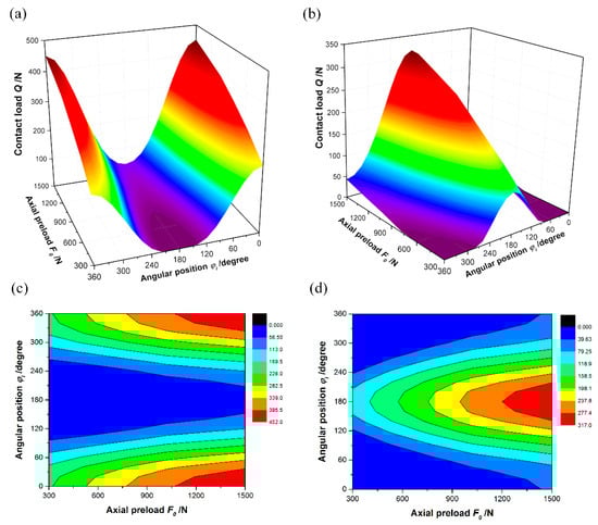
Figure 10.
Effect of axial preload on the contact load distribution of DACBB: (a,b) contact load distribution of the left and the right rows; (c,d) contour map of contact load distribution.
Figure 11 and Figure 12 illustrate the relationship between angular misalignment and the contact load distribution of each row of DACBB. It is assumed that the direction of angular misalignment shown in Figure 2 is positive, and the opposite misalignment direction is negative. In this section, the positive and negative angular misalignment are both considered. As shown in Figure 11, the effect of positive angular misalignment is described. The axial preload is 800 N, and the external radial and axial loads are 1500 N and 500 N, respectively. It is found that angular misalignment has a great influence on the contact load distribution of DACBB. Angular misalignment of inner ring causes uneven contact load distribution in each row of DACBB. This leads to the fluctuation of contact load distribution of each row along the azimuth angle of ball. Meanwhile, the fluctuation is symmetric with respect to the position of 180 degrees due to the symmetric structure of DACBB. Furthermore, angular misalignment has a limited influence on the contact loads of rolling balls near 90 and 270 degrees. This is because that these two positions are the boundary between the upper and lower half part of DACBB. Meanwhile, as demonstrated in Figure 11a, for the left row of DACBB, under lower misalignment angle, all the rolling balls are in contact with inner ring and participate in the load transfer, while under higher angular misalignment, some rolling balls do not participate in the load transfer because they are no longer constrained by the inner ring. This means that the inactive number of rolling balls is closely related to the magnitude of angular misalignment. Moreover, the load zone is the upper half part, and the contact load obviously increases with the increase of angular misalignment. For the right row of DACBB, the main load zone is the lower half part. In the upper half part, the contact load slightly decreases with the increase of angular misalignment. However, in the lower half part, contact load tends to be significantly increased when the misalignment angle increases. Meanwhile, under higher angular misalignment, some rolling balls of upper half part of the right row do not participant in the load transfer. As a matter of fact, when the inner ring of DACBB tilts an angle relative to the outer ring, the upper half part of the left row tends to be “compressed”, while the lower half part tends to be “relaxed”. For the right row, the upper half part tends to be “relaxed” and the lower half part tends to be “compressed”. Accordingly, the contact load distribution will show the behavior described in Figure 11.
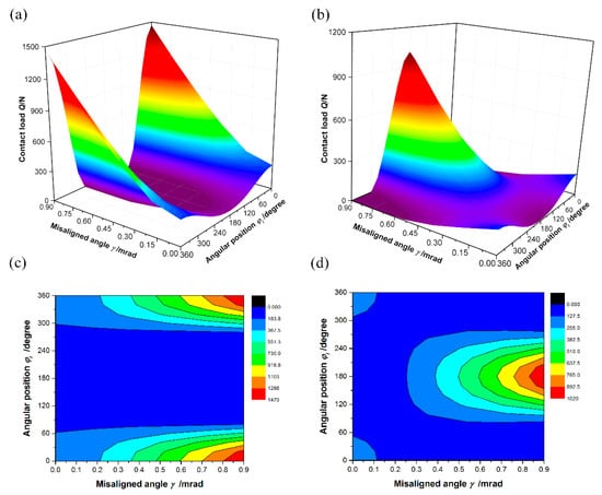
Figure 11.
Effect of positive angular misalignment on the contact load distribution of DACBB: (a,b) contact load distribution of the left and the right rows; (c,d) contour map of contact load distribution.
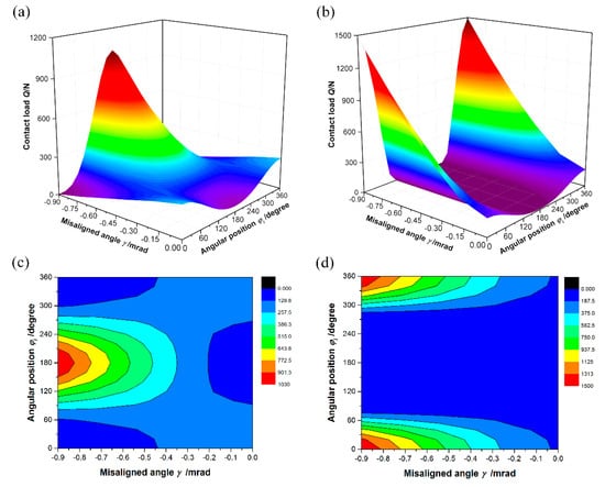
Figure 12.
Effect of negative angular misalignment on the contact load distribution of DACBB: (a,b) contact load distribution of the left and the right rows; (c,d) contour map of contact load distribution.
Figure 12 shows the influence of negative angular misalignment on the contact load distribution of the left and the right rows of DACBB under combined external loads. From Figure 12, it can be observed that, compared to the results shown in Figure 11, the variation of contact load distribution of each row of DACBB will be reversed when the DACBB is loaded by negative angular misalignment. From the results shown in Figure 11 and Figure 12, it can be seen that the angular misalignment will cause the fluctuation of contact load distribution of each row along the azimuth angle of rolling ball. Meanwhile, under lower angular misalignment, the fluctuation is relatively small, while as the angular misalignment increases, the fluctuation is more sever. As a result, the fluctuation of contact load will lead to the fluctuation of contact stress between ball and raceway and further aggravate uneven distribution of contact stress. This condition is very adverse to the fatigue life of DACBB, and even causes premature failure of DACBB. Therefore, excessive angular misalignment should be avoided as far as possible in the applications of DACBB.
4.4. Contact Angle of DACBB
Figure 13 demonstrates the dependence of contact angle of DACBB on the axial preload. The external radial and axial loads are 550 N and 500 N, respectively. The misalignment angle of inner ring is 0.2 mrad. From the results depicted in Figure 13, it is seen that the contact angle is closely dependent on to the axial preload. Under lower axial preload, whether the left or the right row, the curves of contact angle exist the blank, which denotes the area where the contact angle is inexistent because of no direct contact between rolling ball and raceway. Under higher axial preload, the contact angle of the left and the right rows significantly increases with the increase of axial preload. As shown in Figure 13a, contact angles in the upper half part of the left row of DACBB are higher than those of lower half part. However, for the right row, the contact angles in the upper half part is smaller than those of lower half part.
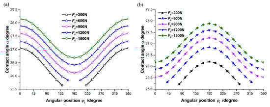
Figure 13.
Contact angle of each row of DACBB under various axial preload: (a) contact angle of the left row; (b) contact angle of the right row.
Figure 14 illustrates the influences of external radial and axial loads on the contact angle of the left and the right rows of DACBB. The axial preload and the external axial load are 500 N and 1000 N, respectively, angular misalignment is 0.5 mrad. As shown in Figure 14a,b, the closely dependence of contact angle of each row of DACBB on the external radial load can be clearly observed. As described in Figure 14a, rolling balls in the lower half part of the left row of DACBB do not direct contact with raceway, thus the contact angle in such a region does not exist. However, in the upper half part, contact angle decreases with the increase of external radial load. For the right row of DACBB, contact angle in the upper half part is inexistent when the external radial load is 1500 N. When the radial load exceeds 1500 N, the contact angle between rolling ball and raceway is existed because all the rolling balls are in contact with the raceway and participate in the load transfer. Meanwhile, contact angle increases with the increase of external radial load.
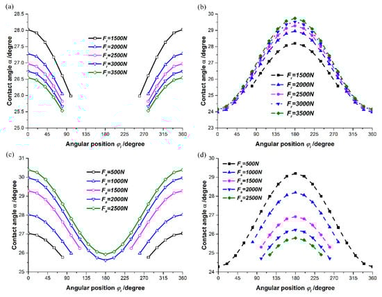
Figure 14.
Contact angle of each row of DACBB under various external loads: (a,b) contact angle of the left and the right rows under external radial load; (c,d) contact angle of the left and the right rows under external axial load.
Figure 14c,d describes the effect of external axial load on the contact angle of the left and the right rows DACBB. The external radial load is 1500 N. As shown in Figure 14c, the contact angle increases with the increase of external axial load. Meanwhile, in the lower half part, the contact angle of the left row does not exist when the axial load is smaller than 2000 N. Once the axial load exceeds 2000 N, the contact angle at each ball position does not exist because all the rolling balls are in contact with raceway. As for the right row of DACBB illustrated in Figure 14d, the contact angle decreases with the increase of axial load. When the DACBB is loaded by the axial load of 500 N, all the rolling balls are in contact with raceway. However, with the increase of external axial load, some rolling balls are no longer contact with raceway. Therefore, the contact angle is inexistent, and the inactive number of rolling balls will be increased.
Figure 15 denotes the effect of angular misalignment on the contact angle of the left and the right rows of DACBB under combined external loads. The axial preload is 800 N, and the external radial and axial loads are 1500 N and 500 N, respectively. As illustrated in Figure 15, it can be observed that angular misalignment of inner ring significantly influences the contact angle of DACBB. Meanwhile, owing to the symmetrical structure of DACBB, contact angle also shows the symmetry similar to that of the contact load described in the figures of Section 4.3. As shown in Figure 15a,b, the influence of positive angular misalignment on the contact angle of the left and right rows of DACBB is described. For the left row of DACBB, it is found that, under lower angular misalignment, the contact angle in the lower half part tends to be decreased. However, once the misalignment angle is higher than 0.1 mrad, the contact angle is in existent in the lower half part. Meanwhile, in the upper half part, the contact angle increases rapidly with the increase of angular misalignment. For the right row of DACBB, the contact angle of upper half part decreases with the increase of angular misalignment. However, when the inner ring misalignment angle is greater than 0.3 mrad, some rolling balls will no longer contact with the raceway and the contact angles at the corresponding azimuth positions are inexistent. In the lower half part, contact angle significantly increases with the increase of misalignment angle.
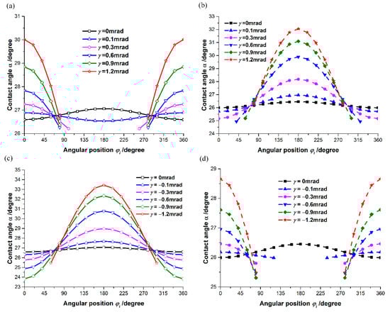
Figure 15.
Influence of angular misalignment on the contact angle of DACBB: (a,b) contact angle of the left and the right rows under positive angular misalignment; (c,d) contact angle of the left and the right rows under negative angular misalignment.
As for the influence of negative angular misalignment of inner ring, the results shown in Figure 15c,d demonstrate that the contact angles of each row of DACBB show similar variations compared to those shown in Figure 15a,b. The main difference is that the situation is reversed for each row. In addition, the value of the contact angle under positive angular misalignment is not equal to that under negative condition.
4.5. Theoretical Fatigue Life of DACBB
Figure 16 shows the impacts of external radial load and angular misalignment on the theoretical fatigue life of DACBB. The external axial load and axial preload are 2000 N and 800 N, respectively. As shown in the Figure 16, the results suggest the nonlinear dependence of DACBB fatigue life on both radial load and angular misalignment. With the increase of external radial load or angular misalignment of inner ring, the fatigue life of DACBB will be significantly decreased. Moreover, it is also found that, under a lower radial load, the fatigue life of DACBB is more sensitive to the angular misalignment than that under higher radial load. Under lower external radial load, the fatigue life of DACBB rapidly decreases with the increase of angular misalignment. However, as the external radial load increases, such downward trend of fatigue life tends to be reduced. Moreover, in the same range of external radial load, the fatigue life of DACBB significantly decreases at lower angular misalignment, especially in the range of 0–0.2 mrad, whilst the change of fatigue life becomes more moderate when the angular misalignment is increased. Furthermore, as shown in the contour map of fatigue life described in Figure 16b, the variation pattern of DACBB fatigue life is almost independent on the direction of angular misalignment. The influence of negative misalignment angle on the fatigue life of DACBB is the same as that of the positive misalignment angle. Although the positive and negative angular misalignments are considered in this part, the figure of fatigue life is asymmetry with respect to 0 mrad. As a matter of fact, as shown in Figure 11 and Figure 12, under positive angular misalignment, the contact load between rolling ball and raceway is not equal to that of negative angular misalignment. Meanwhile, it is also observed that the fatigue life of DACBB does not reach the maximum value at zero angular misalignment, and the value is a little bit greater than zero. Further, the corresponding size of angular misalignment slightly increases with the radial load. This means that the ring angular misalignment of a small size can improve the fatigue life of DACBB under combined loads.
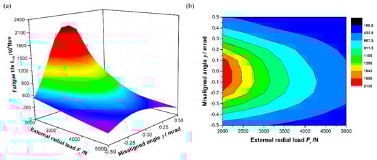
Figure 16.
Influence of angular misalignment and external radial load on the fatigue life of DACBB: (a) fatigue life of DACBB under different radial loads and misalignment angles; (b) contour map of fatigue life.
Figure 17 illustrates the influence of axial preload and angular misalignment on the fatigue life of DACBB. The external radial and axial loads are both 1500 N. As described in Figure 17, as the axial preload gradually increases, the fatigue life of DACBB shows a decreasing tendency. Meanwhile, the fatigue life of DACBB under smaller angular misalignment is more sensitive to the applied axial preload than that under higher angular misalignment. Under lower axial preload, the fatigue life of DACBB significantly decreases with the growth of angular misalignment.
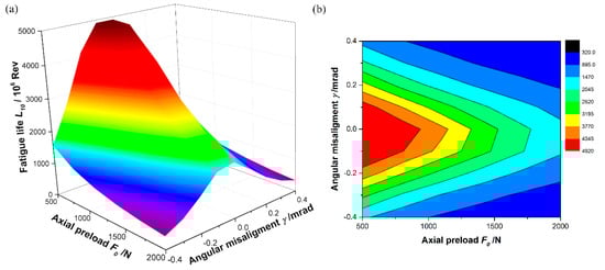
Figure 17.
Dependence of the fatigue life of DACBB on the axial preload and angular misalignment: (a) fatigue life of DACBB under different axial preloads and misalignment angles; (b) contour map of fatigue life.
From the aforementioned analysis and discussion, it is seen that fatigue life of DACBB is closely dependent on the external load and axial preload. Particularly, angular misalignment is also an important factor that greatly affects the fatigue life of DACBB. In fact, as discussed in Figure 11 and Figure 12, angular misalignment significantly influences the contact load distribution of DACBB. It leads to the fluctuation of contact load distribution, thus causes uneven load distribution in the bearing. With the increase of angular misalignment, the fluctuation is more sever. This leads to the fluctuation of contact stress between ball and raceway and further aggravates the uneven distribution of contact stress. The uneven contact stress distribution has a very negative influence on the fatigue life of DACBB, which significantly reduce the fatigue life of DACBB. Therefore, the influence of angular misalignment should be valued in the application and analysis of DACBB.
5. Conclusions
As an important supporting component in the bearing-rotor systems, DACBB commonly runs with angular misalignment. Lots of previous studies demonstrated that misalignment of the inner ring has a great influence on the performance of rolling bearings and rotor systems. However, the misalignment phenomenon in DACBB has not yet been thoroughly studied. Therefore, to study the influence of angular misalignment on the DACBB in theory, this paper established a three degree-of freedom static model of DACBB for back-to-back, face-to-face, and tandem configurations. According to the geometrical relationship inside the bearing, the deformations of DACBB caused by external loads and angular misalignment are systematically analyzed for back-to-back, face-to-face, and tandem configurations. Subsequently, based on the presented model, the influences of angular misalignment, axial preload, and external load on the displacement, maximum contact load, contact load distribution, and actual contact angle of DACBB are studied and discussed. Finally, according to the life theory proposed by Lundberg and Palmgren, the theoretical fatigue life of DACBB under different axial preload, external radial load, and angular misalignment is evaluated in detail. Based on the aforementioned analysis and discussion, the following conclusions can be drawn:
(1) Angular misalignment can considerably increase the contact load between ball and raceway. Angular misalignment will cause the fluctuation of contact load distribution of each row of DACBB, and accordingly lead to the uneven load distribution. With the increase of angular misalignment, the fluctuation is more severe. Contact load increases with the increase of axial preload.
(2) Angular misalignment and axial preload significantly affect the contact zone of DACBB. Under higher angular misalignment, some rolling balls will be no longer constrained by the inner ring. With the increase of axial preload, the contact zone of bearing tends to be increased.
(3) Contact angle increases with the increase of axial preload. With the increase of radial load, contact angle of the left row of DACBB decreases, while it tends to be increased for the right row. Increasing the axial load, the contact angle of the left row increases and the contact angle of the right row decreases. Angular misalignment will cause uneven distribution of contact angle of each row of DACBB. With the increase of angular misalignment, the contact angle can be significantly increased.
(4) With the increase of external radial load or axial preload, fatigue life of DACBB tends to be decreased. Higher angular misalignment considerably reduces the fatigue life of DACBB, so higher angular misalignment should be avoided in the application of DACBB. For the combined loaded DACBB, angular misalignment of certain size can improve the fatigue life of DACBB, and the corresponding size of angular misalignment slightly increases with the increase of radial load.
This paper established a static model for DACBB. However, the rotating effect of the rolling ball is ignored in the analysis. Therefore, the model needs to be extended in the future studies. In addition, this paper only focuses on the characteristics of DACBB. However, DACBB is commonly used to support the bearing-rotor systems. Therefore, the experimental device of bearing-rotor system will be used to study the operating performance of DACBB and the bearing-rotor system under angular misalignment conditions.
Author Contributions
Conceptualization, T.X. and L.Y.; Methodology, T.X.; Validation, T.X.; and K.W.; Formal Analysis, T.X. and K.W.; Writing—Original Draft Preparation, T.X. and L.Y.; Writing—Review and Editing, T.X. and K.W.; Supervision, T.X. and L.Y. All authors have read and agreed to the published version of the manuscript.
Funding
This research was funded by the National Science Foundation of China under Grant No.11872288 and No. 51575425, the Shaanxi Provincial Natural Science Foundation under Grant No. 2019JM-219.
Acknowledgments
The authors would like to express their appreciation to the anonymous reviewers for their help and meaningful comments on this paper.
Conflicts of Interest
The authors declared that there is no conflict of interest with respect to the research, authorship, and/or publication of this article.
Nomenclature
| Adjust factor of fatigue life of DACBB, | |
| Basic rating dynamic load | |
| The coefficient used to adjust the sign of deformation | |
| , and | The index related to the configuration of DACBB |
| Ball diameter, mm | |
| Pitch diameter of DACBB, mm | |
| Axial distance between two rows, mm | |
| Young’s modulus, MPa | |
| Axial preload, N | |
| External radial load, N | |
| External axial load, N | |
| , | Coefficient of inner and outer raceway groove curvature |
| Contact stiffness coefficient of DACBB, N/mm1.5 | |
| Distance between the center of DACBB and the center of rolling ball, mm | |
| The axial distance from the center of inner ring groove curvature to r-axis, mm | |
| Fatigue life, Rev | |
| , | Basic rating life of inner and outer raceway |
| , | The initial distance between the inner/outer groove centers and ball centers, mm |
| , | The distance between the inner/outer groove centers and ball centers, mm |
| Moment load, Nmm | |
| , | Inner ring groove curvature centers of the left and right row of DACBB. |
| Contact load between ball and raceway, N | |
| , | Decomposed component of contact load in radial and axial, N |
| Equivalent contact load of ball-inner/outer raceway | |
| Distance between the inner raceway groove curvature center and z-axis, mm | |
| Radius of inner raceway groove curvature, mm | |
| Radius of outer raceway groove curvature, mm | |
| , | Radial and axial displacement of inner groove curvature centers |
| , | Radial and axial displacements of rolling ball center |
| Number of ball |
Greek Symbols
| Unloaded contact angle, rad | |
| Actual contact angle, rad | |
| Misalignment angle, rad | |
| Total contact deformation, mm | |
| Radial displacement, mm | |
| Axial displacement, mm | |
| , | Deformation components caused by angular misalignment, mm |
| Poisson’s ration | |
| Axial deformation, mm | |
| The azimuth angle of rolling ball, rad | |
| , | The clearances between ball and inner/outer raceway, mm |
References
- Luo, J.; Luo, T. Calculation and Application of Rolling Bearing; China Machine Press: Beijing, China, 2009. [Google Scholar]
- Harris, T.A. Rolling Bearing Analysis; John Wiley and Sons J. Wiley: New York, NY, USA, 2001. [Google Scholar]
- Abele, E.; Altintas, Y.; Brecher, C. Machine tool spindle units. CIRP Ann-Manuf. Technol. 2010, 59, 781–802. [Google Scholar] [CrossRef]
- Palmgren, A. Ball and Roller Bearing Engineering; SKF Industries: Philadelphia, PA, USA, 1959. [Google Scholar]
- Jones, A.B. A general theory for elastically constrained ball and radial roller bearings under arbitrary load and speed conditions. J. Basic Eng. 1960, 82, 309–320. [Google Scholar] [CrossRef]
- Harris, T.A.; Mindel, M.H. Rolling element bearing dynamics. Wear 1979, 23, 311–337. [Google Scholar] [CrossRef]
- De Mul, J.M.; Vree, J.M.; Maas, D.A. Equilibrium and associated load distribution in ball and roller bearings loaded in five degrees of freedom while neglecting friction—Part I: General theory and application to ball bearings. J. Tribol.-Trans. ASME 1989, 111, 142–148. [Google Scholar] [CrossRef]
- Noel, D.; Ritou, M.; Furet, B.; Le Loch, S. Complete analytical expression of the stiffness matrix of angular contact ball bearings. J. Tribol.-Trans. ASME 2013, 135, 041101. [Google Scholar] [CrossRef]
- Zhang, J.; Fang, B.; Zhu, Y.; Hong, J. A comparative study and stiffness analysis of angular contact ball bearings under different preload mechanisms. Mech. Mach. Theory 2017, 115, 1–17. [Google Scholar] [CrossRef]
- Yan, K.; Hong, J.; Zhang, J.; Mi, W.; Wu, W. Thermal-deformation coupling in thermal network for transient analysis of spindle-bearing system. Int. J. Therm. Sci. 2016, 104, 1–12. [Google Scholar] [CrossRef]
- Yang, Z.; Li, B.; Yu, T. Influence of structural parameters and tolerance on stiffness of high-speed ball bearings. Int. J. Precis. Eng. Manuf. 2016, 17, 1493–1501. [Google Scholar] [CrossRef]
- Wang, W.Z.; Hu, L.; Zhang, S.G.; Kong, L.-J. Modeling high-speed angular contact ball bearing under the combined radial, axial and moment loads. Proc. Inst. Mech. Eng. Part C—J. Eng. Mech. 2014, 228, 852–864. [Google Scholar] [CrossRef]
- Wang, W.; Hu, L.; Zhang, S.; Zhao, Z.; Ai, S. Modeling angular contact ball bearing without raceway control hypothesis. Mech. Mach. Theory 2014, 82, 154–172. [Google Scholar] [CrossRef]
- Li, X.; Yu, K.; Ma, H.; Cao, L.; Luo, Z.; Li, H.; Che, L. Analysis of varying contact angles and load distributions in defective angular contact ball bearing. Eng. Fail. Anal. 2018, 91, 449–464. [Google Scholar] [CrossRef]
- Fang, B.; Zhang, J.; Hong, J.; Zhu, Y. Quick calculation method and contact angle analysis for high-speed angular contact ball bearing under combined loads. J. Xi’an Jiaotong Univ. 2017, 51, 115–121. [Google Scholar]
- Fang, B.; Zhang, J.; Yan, K.; Hong, J.; Wang, M.Y. A comprehensive study on the speed-varying stiffness of ball bearing under different load conditions. Mech. Mach. Theory 2019, 136, 1–13. [Google Scholar] [CrossRef]
- Wang, H.; Han, Q.; Zhou, D. Nonlinear dynamic modeling of rotor system supported by angular contact ball bearings. Mech. Syst. Signal Process. 2017, 85, 16–40. [Google Scholar] [CrossRef]
- Liu, J.; Tang, C.; Wu, H.; Xu, Z.; Wang, L. An analytical calculation method of the load distribution and stiffness of an angular contact ball bearing. Mech. Mach. Theory 2019, 142, 103597. [Google Scholar] [CrossRef]
- Zmarzły, P. Influence of the internal clearance of ball bearings on the vibration level. In Proceedings of the 4rd International Conference Engineering Mechanics, Svratka, Czech Republic, 14 May 2018; pp. 961–964. [Google Scholar] [CrossRef]
- Hinton, W.R. An investigation into the causes of ball bearing failures in types P2 and P3 engine-driven generators. Wear 1970, 16, 3–42. [Google Scholar] [CrossRef]
- Hinton, W.R. A theoretical study of the effect of angular misalignment on ball bearing cage life. Wear 1970, 16, 175–187. [Google Scholar] [CrossRef]
- Taha, M.M.A. The influence of bearing misalignment on the performance of helicopter gear boxes. Wear 1983, 92, 79–97. [Google Scholar] [CrossRef]
- Bae, G.H.; Tong, V.C.; Hong, S.W. Fatigue Life Analysis for angular contact ball bearing with angular misalignment. J. Korean Soc. Precis. Eng. 2016, 33, 53–61. [Google Scholar] [CrossRef]
- Xu, R.; Shen, X.S.; Fan, Q.; Wang, X.-Q.; Chen, Y. Failure analysis on aero-engine spindle ball bearing. Bearing 2012, 20–24. [Google Scholar] [CrossRef]
- Zhang, X.; Han, Q.; Chu, F. Contact angle of ball bearings based on a simplified Jones-Harris method. J. Vib. Shock 2013, 32, 170–175. [Google Scholar]
- Ye, Z.; Wang, L.; Zhang, C.; Gu, L. Impact of shaft coaxiality on the local stiffness of angular contact ball bearing. Adv. Mater. Res. 2012, 418–420, 1026–1030. [Google Scholar] [CrossRef]
- Tong, V.C.; Hong, S.W. Study on the running torque of angular contact ball bearings subjected to angular misalignment. Proc. Inst. Mech. Eng. Part J—J. Eng. Tribol. 2018, 232, 890–909. [Google Scholar] [CrossRef]
- Oktaviana, L.; Tong, V.C.; Hong, S.W. Skidding analysis of angular contact ball bearing subjected to radial load and angular misalignment. J. Mech. Sci. Technol. 2019, 33, 837–845. [Google Scholar] [CrossRef]
- Liao, N.T.; Lin, J.F. An analysis of misaligned single-row angular-contact ball bearing. J. Mech. Des. 2004, 126, 370–374. [Google Scholar] [CrossRef]
- Xiong, W.; Zhou, Y.; Zhao, Z.; Lü, L. Quantitative research on the permissible tilt angle of high-speed angular contact ball bearings. J. Mech. Eng. 2015, 51, 46–52. [Google Scholar] [CrossRef]
- Zhang, Y.; Zhang, M.; Wang, Y.; Xie, L. Fatigue life analysis of ball bearings and a shaft system considering the combined bearing preload and angular misalignment. Appl. Sci. 2020, 10, 2750. [Google Scholar] [CrossRef]
- Zhang, Y.; Fang, B.; Kong, L.; Li, Y. Effect of the ring misalignment on the service characteristics of ball bearing and rotor system. Mech. Mach. Theory 2020, 151, 103889. [Google Scholar] [CrossRef]
- Yang, L.; Xu, T.; Xu, H.; Yao, W. Mechanical behavior of double-row tapered roller bearing under combined external loads and angular misalignment. Int. J. Mech. Sci. 2018, 142, 561–574. [Google Scholar] [CrossRef]
- Xing, Y.; Xu, H.; Pei, S.; Zhang, X.; Chang, W. Mechanical analysis of spherical roller bearings due to misalignments between inner and outer rings. Proc. Inst. Mech. Eng. Part C—J. Eng. Mech. 2016, 231, 3250–3262. [Google Scholar] [CrossRef]
- Geng, K.; Lin, S. Effect of angular misalignment on the stiffness of the double-row self-aligning ball bearing. Proc. Inst. Mech. Eng. Part C—J. Eng. Mech. 2020, 234, 946–962. [Google Scholar] [CrossRef]
- Tong, V.C.; Hong, S.W. The effect of angular misalignment on the stiffness characteristics of tapered roller bearings. Proc. Inst. Mech. Eng. Part C—J. Eng. Mech. 2017, 231, 712–727. [Google Scholar] [CrossRef]
- Tong, V.C.; Hong, S.W. Fatigue life of tapered roller bearing subjected to angular misalignment. Proc. Inst. Mech. Eng. Part C—J. Eng. Mech. 2016, 230, 147–158. [Google Scholar] [CrossRef]
- Tong, V.C.; Hong, S.W. The effect of angular misalignment on the running torque of tapered roller bearings. Tribol. Int. 2016, 95, 76–85. [Google Scholar] [CrossRef]
- Bercea, I.; Nelias, D.; Cavallaro, G. A unified and simplified treatment of the non-linear equilibrium problem of double-row rolling bearings. Part 1: Rolling bearing model. Proc. Inst. Mech. Eng. Part J—J. Eng. 2003, 217, 205–212. [Google Scholar] [CrossRef]
- Lim, T.C.; Singh, R. Vibration transmission through rolling element bearings, part I: Bearing stiffness formulation. J. Sound Vib. 1990, 139, 179–199. [Google Scholar] [CrossRef]
- Royston, T.J.; Basdogan, I. Vibration transmission through self-aligning (spherical) rolling element bearings: Theory and experiment. J. Sound Vib. 1998, 215, 997–1014. [Google Scholar] [CrossRef]
- Gunduz, A.; Singh, R. Stiffness matrix formulation for double row angular contact ball bearings: Analytical development and validation. J. Sound Vib. 2013, 332, 5898–5916. [Google Scholar] [CrossRef]
- Zhang, J.; Fang, B.; Hong, J.; Wan, S.; Zhu, Y. A general model for preload calculation and stiffness analysis for combined angular contact ball bearings. J. Sound Vib. 2017, 411, 435–449. [Google Scholar] [CrossRef]
- Yang, Z.; Chen, H.; Yu, T. Effects of rolling bearing configuration on stiffness of machine tool spindle. Proc. Inst. Mech. Eng. Part C—J. Eng. Mech. 2018, 232, 775–785. [Google Scholar] [CrossRef]
- Kogan, G.; Klein, R.; Kushnirsky, A.; Bortman, J. Toward a 3D dynamic model of a faulty duplex ball bearing. Mech. Syst. Signal Proc. 2015, 54, 243–258. [Google Scholar] [CrossRef]
- Petersen, D.; Howard, C.; Sawalhi, N.; Ahmadi, A.M.; Singh, S. Analysis of bearing stiffness variations, contact forces and vibrations in radially loaded double row rolling element bearings with raceway defects. Mech. Syst. Signal Proc. 2015, 50, 139–160. [Google Scholar] [CrossRef]
- Deng, S.; Dong, X.; Cui, Y.; Hu, G. Analysis of dynamic stiffness characteristics of double-row angular contact ball bearings. Acta Armamentarii 2015, 36, 1140–1146. [Google Scholar]
- Xie, L.; Ma, J.; Jin, L.; Yang, Z. Analysis on dynamic stiffness of paired angular contact ball bearings. Bearing 2019, 12, 11–15, 27. [Google Scholar] [CrossRef]
- Lin, S.; Jiang, S. Study of the stiffness matrix of preloaded duplex angular contact ball bearings. J. Tribol.-Trans. ASME 2019, 141, 032204. [Google Scholar] [CrossRef]
- Lin, S.; Jiang, S. Dynamic characteristics of motorized spindle with tandem duplex angular contact ball bearings. J. Vib. Acoust.-Trans. ASME 2019, 141, 12. [Google Scholar] [CrossRef]
- Tong, V.C.; Hong, S.W. Analysis of the stiffness and fatigue life of double-row angular contact ball bearings. J. Korean Soc. Precis. Eng. 2017, 34, 813–821. [Google Scholar] [CrossRef]
- Liu, J.; Shao, Y. Overview of dynamic modelling and analysis of rolling element bearings with localized and distributed faults. Nonlinear Dyn. 2018, 93, 1765–1798. [Google Scholar] [CrossRef]
- Zhang, J.; Fang, B.; Hong, J.; Zhu, Y. Effect of preload on ball-raceway contact state and fatigue life of angular contact ball bearing. Tribol. Int. 2017, 114, 365–372. [Google Scholar] [CrossRef]


© 2020 by the authors. Licensee MDPI, Basel, Switzerland. This article is an open access article distributed under the terms and conditions of the Creative Commons Attribution (CC BY) license (http://creativecommons.org/licenses/by/4.0/).