1. Introduction
Foams are generally an essential class of materials that are ubiquitous in impact mitigation applications, due to their inherent high-energy absorption ability. Such an ability is associated with its cellular structure through multiple deformations or failure mechanisms dependent on the classification of the foam structure, i.e., open-cell or closed-cell. In general, the reversible or irreversible deformations (e.g., elastic deformation, bulking, and densification) dissipate the incoming impact energy through the strain energy resulting from the shape change during the loading scenario. Another intrinsic property of foams is the significant reduction of weight compared to its base materials, since the solid is either orderly or randomly arranged in the three-dimensional space during the foaming process. A sub-class of the foam family of materials is polymeric foams, which are universally used in protective sports equipment to guard against low to moderate impacts such as those experienced by athletes. Polymeric foams strategically combine the fundamental properties of cellular solids by providing superior energy absorption to weight ratio, which is imperative for novel and innovative personal armors for athletic and military applications [
1]. To further improve the performance of polymeric foams in dynamic loading scenarios, dense polymers with superior impact mitigation have been continuously sought by scientists and engineers to create the cellular microstructure of foams.
The macroscale deformation response of polymeric foams is sensitive to the attributes of the loading conditions, including the duration and amplitude of the impact, as well as the strain rate. This sensitivity is an interplay between the properties of the base or parent polymer and the cellular microstructure [
2,
3,
4,
5,
6,
7]. At the fundamental level, the mechanical behavior of foams is hinged on the interconnectivity of the solid forming the basic cell structure, which gives rise to different energy dissipation and shunting mechanisms that are tunable through the geometry of the cellular microstructure. Gibson and Ashby exhaustively treated the topic of the structure and properties of foams by generally classifying their microstructures as either open-cell or closed-cell, as well as partially-open/partially-closed cells [
2]. The latter, if it exists, usually is a material with segregated regions of open-cells adjacent to regions of closed-cells, due to the difficulty in strategically controlling the dispersion of the blowing or foaming agent into the polymer melt during the manufacturing process. Open-cell foams are more desirable for energy-absorption applications, due to their horizontal plateau behavior, while closed-cell foams are more desirable for cushioning and load distribution applications [
8,
9,
10]. Thus, combining the advantages of the open and closed microcellular structures would result in a foam material with tailorable properties explicitly designed for a target application. The material selection can be further improved if shape memory properties are intrinsically or extrinsically induced on the foam microstructure [
11]. Recently, our group reported a manufacturing process that produced a hybrid structure foam encompassing the advantages of closed and open cells [
5,
6,
12,
13]. A byproduct of the foaming process is the nucleation of dense microspheres, which get deposited on the inner walls of the cells during the final water drainage process, resulting in additional reinforcement. The latter is the focus on the research leading to this paper. It is important to note the difference between enhancing properties by tailoring the molecular structure through the combination of urethane and urea bonds [
11], the addition of microparticles to form composite materials [
3], and the approach reported here, where polyurea microspheres form during the mechanical mixing process and act a reinforcement.
A promising material for foaming is polyurea, a thermoset elastomer with superior structural and mechanical properties coupled with hygrothermal and chemical resistance that warranted widespread attention in industrial and scientific applications [
14,
15,
16,
17,
18,
19]. The superior impact mitigation properties are driven by the underlying segmental microstructure of polyurea, which comprises of a rigid hard phase composed of aromatic moieties, dispersed in a compliant, aliphatic soft phase [
20]. The ratio of these hard and soft phases is controlled by tuning the stoichiometric ratio of the isocyanate and amine constituents [
21]. It is essential to differentiate between the chemical structure of the common polyurethane material, including its foam derivatives, and the polyurea discussed here. Generally, dense polyurea is well situated within the coating industry as a viable solution for a wide range of applications, e.g., water well and roof protection, given its ability to retain the majority of its mechanical properties even after exposure to ultraviolet radiation for extended periods [
22,
23,
24,
25]. It was then the motivation of this research to introduce a novel polyurea foam microstructure manufactured through a simple and green manufacturing process that also self-reinforces the cell walls with polyurea microspheres (a byproduct of the process), hence, creating a new polymer/polymer foam composite [
5,
6,
12]. The notion of ‘composite’ is motivated based on the concurrent forming of polyurea in a different form factor, i.e., the microsphere, which was shown to be stiffer than its dense counterpart [
26]. The introduction of this new class of polymeric foams will promote scientific, theoretical, and experimental investigations beyond those presented within the scope of this paper. It is important to note that other researchers concurrently investigated different variations of polyurea foams, based on the same constituents, where their results corroborate and support the notion of this foam having superior impact mitigation properties [
26,
27]. Polyurea foams can be further exploited in many applications, including thermal insulation, filtration, and acoustic isolation, to name a few.
Previous studies confirmed that polyurea foams inherit superior mechanical properties, including viscoelastic and impact mitigation attributes, of their dense counterpart [
4,
5,
6,
28,
29,
30,
31]. Different density variations were fabricated and characterized using quasi-static and impact testing. Reed et al. first performed the microstructure analysis [
5]. They noted that their version of polyurea foam exhibit a hierarchical microcellular structure consisting of large perforated semi-closed spherical cells surrounded by smaller closed spherical cells, where the mean diameters, calculated based on image analysis of scanning electron microscope micrographs, were found to be 370 ± 162 μm and 69 ± 18 μm, respectively [
5]. Following the Ogden hyperfoam model, an exhaustive quasi-static characterization demonstrated the hyperelastic response of polyurea foams extending from linear elasticity to the onset of densification, and the results and the experimental data were found to be in good agreement [
5]. Reed and coworkers also found that the elastic and energy-absorbing properties of polyurea foams outperformed a benchmark, off-the-shelf, closed-cell foam (also with spherical microcellular structure) [
5]. Youssef et al. then tested the same polyurea foams in response to low-velocity impacts and confirmed the predictions of Reed et al. regarding the remarkable impact performance [
6]. Contemporary to the investigations mentioned above, Ramirez et al. also foamed polyurea using a vacuum environment distinctively different from the polyurea foams reported herein that were foamed and cured in ambient conditions [
4,
28,
29,
30,
31].
2. Materials and Methods
Polyurea foam sheets were fabricated using a slab molding technique, with dimensions of 30.5 cm Long × 30.5 cm Wide × 1.9 cm Thick. The foam was prepared by combining Versalink
® P1000 (C
70H
124N
2O
16, oligomeric diamine, AirProducts & Chemicals., Allentown, PA, U.S.A.) and Isonate
® 143 L (C
15H
10N
2O
2, modified Methylene Diphenyl Diisocyanate, Dow Chemical Company, Midland, MI, U.S.A.) with DI H
2O (deionized water) as the blowing agent (since the reaction of DI H
2O with isocyanate results in CO
2) in a ratio of 12:3:40 by weight [
5,
12,
13]. The relatively large water content was required to protect the mechanical mixer from self-binding, but it consistently and repeatedly results in polyurea foam with desired properties, e.g., density. Polyurea foams with a density of 227.3 ± 4.5 kg·m
−3 and 355.8 ± 18.6 kg·m
−3 were fabricated by adjusting the amount of the diamine, isocyanate, and deionized water mixture to tune the volume of the foamed slurry. The DI H2O was first thoroughly mixed with Versalink
® P1000 for 45 s, followed by mixing the Isonate
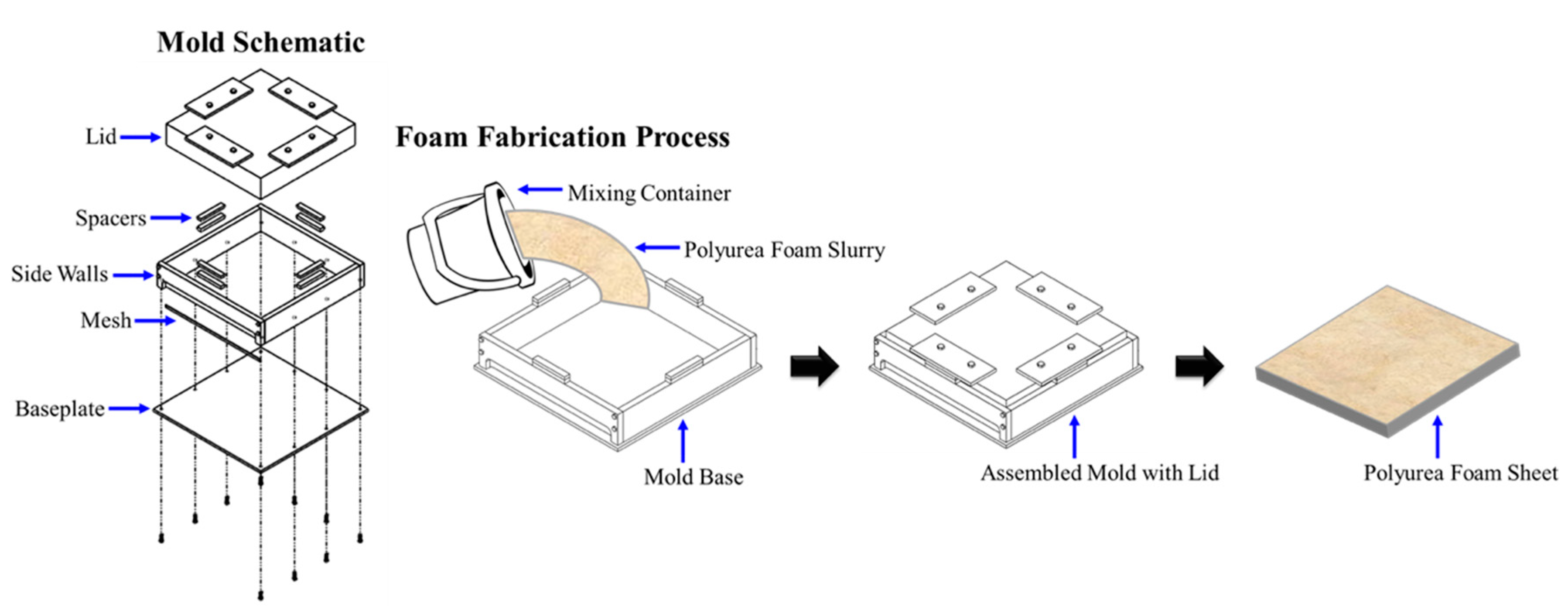
® 143 L for an additional 45 s. The foam slurry, created by vigorously mixing the constituents, was quickly transferred to the mold, since it was observed to have a short pot-life ranging from 3–5 min. A nonstick liner was sprayed on the mold cavity inside to assist in releasing the foam upon curing. The poured volume of the foam slurry added to a preset mold cavity resulted in the desired thickness and density. Samples in the mold were cured under ambient conditions for 24 h without heat and vacuum. The demolded foam sheets were left for an additional 48 h in the same conditions to allow for the natural evaporation of the water residue.
Figure 1 schematically summarizes the foam fabrication process. The reader is referred to Ref. [
12] for additional details about the foam manufacturing process.
Upon release from the mold, several samples were extracted from the sheets, and the microstructure of the novel polyurea foam was analyzed using an electron microscope (FEI, Quanta 450) to elucidate the underlying mechanisms responsible for the unique structure. Once SEM (scanning electron microscope) micrographs were obtained, the cell structure of the foam was measured using ImageJ (NIH, U.S.A.). The SEM micrographs were first calibrated within ImageJ. The circular perimeter of individual cells and microspheres were then measured and used to calculate their nominal diameters. The average diameter was calculated based on measurements of the cross-sectional area of exposed cells in the SEM micrographs. Additional image analysis was performed on the same SEM micrographs to estimate the open-space in each cell, resulting in the average perforated area. In separate investigations, the mechanical properties of the foam were assessed and found to exhibit superior impact mitigation properties suitable for integration in low-velocity sports protective gears [
5,
12]. The reader is referred to these references for compressive discussion about the mechanical characterizations of the polyurea foam discussed here, which were also benchmarked to an off-the-shelf foam with spherical microcellular structure. It is worth noting that the ability to produce foams with different densities using the same process prompted its investigation for density-graded foam midsoles for orthotics [
1]. It is predicted that density gradation would significantly improve the strength and energy absorption performance [
1].
3. Results and Discussion
The SEM micrographs of a low-relative density of 0.21 (EML227) and high-relative density (EML350) of 0.33 polyurea foams are shown in
Figure 2. The average cell diameter of the EML227 (
) foam was 134.5 ± 108.5 µm, which is nearly 48% larger the cell diameter of EML350 (
= 90.9 ± 48.9 µm) based on micrographic analysis of the SEM micrographs. The variation between the cell sizes of EML227 and EML350 is attributed to the interplay between the desired final sheet thickness as a function of the initial mixing ratio of the chemicals and the blowing agent. That is to say, the volume of the foam cavity was kept constant, while adjusting the amount of the poured foam slurry—which resulted in congregating the entrapped gas bubbles, yielding an overall smaller cell diameter. Lastly, the standard deviation of the cell size is associated with a hierarchal microcellular structure, since the cell walls separating adjacent large microcells tend to encompass cells with smaller diameters (circled in
Figure 2a,d for EML227 and 350, respectively). Such a hierarchal microcellular structure plays a significant role in the quasi-static mechanical behavior of the foam [
5,
6,
32].
The generation of carbon dioxide gas bubbles based on the reaction between isocyanate and DI H
2O continues to expand the cell walls resulting in the formation of the spherical microcellular foam structure, as shown in
Figure 2. The carbon dioxide generation process is said to be a self-limiting chemical reaction, which impedes the transformation of the microcellular structure to a polyhedral geometry. Moreover, the relatively short curing time of the polyurea elastomer also limits the expansion process [
33]. The large perforations around the cell surfaces are due to the interplay between the internal gas pressure and the proximity of adjacent cells, or shared walls between neighboring cells. A close examination of
Figure 2 elucidates the perforation formation process. Portions of the cell walls appear to be much thinner sheaths, sites encircled in red in
Figure 3, depicting areas where large perforations would have been created if the cell wall expansion had continued, due to CO
2 generation. The ruptured edges are also wrapped towards the cell with lower internal pressure, confirming the large perforation formation mechanism through a close examination of the periphery of existing perforations. The rupture process of the thin sheaths commences when the strength and stiffness of the viscous polymer sheath cannot resist the deformation induced by the applied tension in the cell wall, due to the difference in the internal gas pressure between adjacent cells. The mechanical properties of the curing polyurea can be determined through rheological studies, which are the focus of future research. Additionally, stretch marks (insets in
Figure 3) on the cell walls reveal the effect of the gas pressure entrapped inside the cells during the curing process before setting. The pressure from the mold enclosure to control the dimensions of the sheets also enhances the applied load. The formation of the small holes is an independent process and is explained next.
Omnipresent small holes are preferentially located on one side of the cell in addition to the large perforations discussed above, where the nucleation of the holes is associated with the localized precipitation of dispersed isocyanate during the violent mixing process. That is, the formation of micro-holes implies a localized concentration of isocyanate that locally generates CO2 when reacting with the entrapped DI H2O. As a result, the cell walls of the polyurea foam contain only ~7.6% and ~4.5% open-space, comprising of perforations and holes for EML227 and EML350, respectively. The existence of the perforations promoted the classification of our polyurea foam as ‘semi-closed cell’ or ‘partially-perforated’ foam. A transversely isotropic mechanical behavior is then implied by the newly reported ‘semi-closed cell’ foam structure. In contrast, anisotropic behavior is ascribed to the partially-open/partially-closed microcellular structure at the macroscale level. A comprehensive mechanical characterization of the anisotropy of the foam will be undertaken in future research.
The favored direction at which the small holes nucleate on the lower portion of the foam cell is shown in
Figure 2b,e, which is attributed to two concurrent processes. The aggressive mechanical mixing of amine and isocyanate in DI H
2O results in an emulsion of chemicals that polymerize and create micro-holes and microspheres (discussed next) [
34]. Second, the foam slurry floats above the surface of the water as it starts to form since the foam density is less than that of DI H
2O. The excess water is then quickly drained (towards the blue arrows on
Figure 2b,e), pulling the suspended microspheres towards the bottom of the cell. The deposition of the microspheres occurs early in the curing stage since the foam slurry is rapidly transferred to the model given its low pot life, which indicates a local chemical reaction between excess isocyanate and residual DI H
2O producing carbon dioxide, therefore, the creation of small holes at the cell walls as discussed above. It is essential to differentiate between the syntheses of well-connected, hierarchical foam structure with microspheres from the previously reported polyurea microcapsules [
35]. The latter exhibited no perforations, were individual unconnected capsules, and were unreinforced. Hence, the reported microstructure is unique, since it combines attributes of a foam structure with a self-reinforcement that was not reported a priori, to the best of the authors’ knowledge.
The reinforcement of polyurea foam by the concurrent nucleation (a byproduct of the manufacturing process) and deposition of polyurea microspheres constitutes a unique aspect of our foam (
Figure 4), or in short, our polyurea foam is a polymer/polymer composite. The deposited microspheres are expected to enhance the strength and increase the force required to deform the walls during dynamic loading scenarios, e.g., low-velocity impacts. The high-speed, aggressive mechanical mixing process of the constituents results in the isocyanate reacting with the emulsified amine molecules in deionized water solution, hence, creating microspheres through a modified precipitation polymerization process. It is, however, important to emphasize that the microspheres are a byproduct of the foaming process, due to the emulsification of the polyurea chemicals in DI H
2O using violent mechanical mixing. The residual stresses at the interface between the two composite phases are substantially reduced, due to the absence of elastic mismatch, as well as the chemical mismatch between the cell walls and the reinforcing microspheres phase, i.e., eliminating the inter-phasic region. Do et al., who also delineated the polyurea microsphere process [
36], recently reported the premise of a homo polymer-polymer composite material.
As mentioned earlier, one of the most prominent potential applications for polyurea foams is the mitigation of biomechanical impact loadings, such as those experienced by American football players in helmet-to-helmet or helmet-to-ground impacts [
4,
5,
6,
12,
26,
28,
29,
30,
31]. The performance of foams in such impact scenarios can be evaluated from the results of quasi-static mechanical testing [
8,
9,
10] to elucidate the ability of the foam to resist deformation, i.e., elastic modulus, as well as the amount of strain energy per unit volume represented by the area under the stress-strain curve. To draw a distinction between our polyurea foams and others currently available on the open market, 19.1 mm thick foam plugs with a diameter of 41.3 mm and 25.4 mm were extracted from EML227 and EML350, respectively. Alternatively, 25.4 mm Dia. × 14.0 mm thick samples were extracted from a commercially available impact mitigating foam (~390 kg·m
−3, closed-cell) used in motorcycle helmets and padding. The latter served as a benchmark control for comparison of performance, and the reduction in diameter for the higher density foam plugs was to accommodate the force limitations of the testing apparatus. Previously mechanical testing showed that the EML350 foam resulted in a density-normalized absorbed energy per unit volume of 991 Pa/kg·m
−3, while EML227 and the control foams were found to be similar for this metric, resulting in density-normalized absorbed energies per unit volume of 536 Pa/kg·m
−3 and 532 Pa/kg·m
−3, respectively, with EML227 being 42.8% lighter. Moreover, the specific modulus (modulus per unit density) for both polyurea foam variations were found to be superior in comparison to the specific modulus of the control foam, where EML227 and EML350 have specific moduli of 2.52 and 2.81 Pa/kg·m
−3, while the control reported only 1.73 Pa/kg·m
−3.
In a helmet impact scenario, the kinetic energy can be represented as,
, where
is the mass of the head (taken in subsequent calculations to be 5 kg [
37]),
is the acceleration of the head,
is the initial velocity, and
is the duration of the impact (estimated to be 10 ms for biomechanical impact [
37]). Thus, the kinetic energy (due to this impact) can be compared to the strain energy in the foam based on the quasi-static data reported in the previous paragraph to determine the effectiveness of EML350 and control foams in decelerating an incoming impact. EML227 foam was not included in the comparison, due to the large density difference with the other two types of foams. To estimate the strain energy, the density-normalized absorbed energy per unit volume is multiplied by the volume of the impact region and the density of the respective foam. The volume of the impact region was calculated based on an estimated 10 cm impact diameter and the thickness of a typical helmet foam liner (2 cm). The results show that EML350 can tolerate up to 47.6 g of acceleration, while the control foam (with comparable density) can only sustain an acceleration of 36.8 g. The estimated 29% increase in impact mitigation ability through tolerance to higher acceleration is attributed to the unique microstructure of our novel polyurea foam.
Finally, a discussion about the reinforcing effect due to the nucleation and deposition of dense polyurea microspheres during the foam fabrication process is warranted to demonstrate the substantial change in the response upon reinforcing. The stiffening phenomenon is emphasized locally, due to the deposition of the microspheres on the inner surface of the microcell of the foam; hence, it is not conducive for experimental probing. Here, we alternatively leverage a newly developed analytical model by some of the current authors to elucidate the increase in stiffness, due to the presence of microspheres. In this model, the dense microspheres were modeled as uniformly distributed over the inner surface in both polar and azimuth directions. The model is based on linear elasticity, which is sufficient to elucidate the stiffening effect. Given the lack of transitional interphase between the microsphere and the foam wall, as explicated from the inset of the micrograph presented in
Figure 5a, the material entrapped in the wall of the microcell and that of the microspheres were taken to be the same. The material was assumed to have an elastic modulus of 10 MPa and a Poisson’s ratio of 0.25. It is important to note that changes to the properties would linearly adjust the results given the underlying linear isotropy assumption in the model. The displacement resulting from the applied load was then calculated over one-quarter of the unit cell geometry. A schematic of a representative microcell with the reinforcing microspheres is shown in
Figure 5b.
Figure 6 shows an example of the analytical results demonstrating the difference in the mechanical response of a unit cell (i.e., microcell, see
Figure 5b) without any reinforcement and with 144 uniformly distributed microspheres. In the simulation leading to the results in
Figure 6, a modeled microcell without any reinforcing microspheres was first subjected to a load of 30 N distributed over an area defined by a zenith angle of 12° divided symmetrically. The microcell was assumed to have a diameter of 140 μm, which is within the range reported by Reed et al. [
5]. Subsequently, the barren microcell was reinforced with microspheres with a diameter ratio of 0.1 (i.e., microsphere diameter/microcell diameter = 0.1), which was chosen to be in the same order of magnitude, observed by Do et al., while producing standalone polyurea microspheres [
36]. All other loadings and boundary conditions were the same for both cases of the reinforced and barren microcells.
The stiffening effect is substantiated based on three observations from
Figure 6, namely, the deformation in the zenith and azimuth directions and the overall change in the deformed perimeter. The normalized zenith deformation in response to a 30 N applied load decreased by 35% upon introducing the reinforcing microsphere, where the normalized zenith radius changed from 0.71 to 0.81 for the barren and reinforced microcells, respectively. Similarly, the equator, i.e., normalized azimuth radius, exhibited a 63% reduction in the deformation for microsphere-reinforced microcell. Specifically, the equator for the barren case increased by 25%, while only expanding by 9% for the reinforced case. Therefore, the reduction in deformation under the same loading conditions signifies the increase in the stiffness, regardless of the direction. Remarkably, the addition of the reinforcing microspheres also changed the overall deformation behavior of the entire perimeter, such that the barren microcell experienced elastic instability resembled in the buckling of the wall. This is consistent with the plateau region in a typical foam response, the onset of which is associated with many deformation mechanisms, including elastic instability [
2]. On the other hand, the reinforced microcell remained in the elastic region without showing any cell wall buckling, implying the ability of reinforced polyurea foam to manage the incoming low-velocity impact scenarios better than the smooth and barren microcell. Reed et al. recently experimentally demonstrated this observation, where a polyurea foam with a relative density of 0.33 reported ~71.7 kJ·m
−3 of strain energy under the stress-strain curve. In comparison, a benchmark foam with barren microstructure only exhibited energy of 51.9 kJ·m
−3, for the same strain history [
5]. In essence, Reed and coworkers provided the experimental evidence for the superiority of reinforced foam, which was analytically demonstrated and confirmed herein [
5]. In closing, it is worth noting that the analytical results of our model are consistent with elastic predictions of the spherical microcapsule geometry as delineated in [
38].


