Article

Investigations of Adhesion under Different Slider-Lube/Disk Contact States at the Head–Disk Interface

1
College of Mechanical and Electronic Engineering, Nanjing Forestry University, Nanjing 210037, China
2
School of Mechanical Engineering, University of Science and Technology Beijing, Beijing 100083, China
*
Author to whom correspondence should be addressed.
Appl. Sci. 2020, 10(17), 5899; https://doi.org/10.3390/app10175899
Submission received: 8 July 2020 / Revised: 22 August 2020 / Accepted: 24 August 2020 / Published: 26 August 2020
(This article belongs to the Special Issue Tribology in Machine Components)

Abstract

:
Adhesion is the key factor influencing the failure of the hard disk drive operating under ultra-low flying height. In order to mitigate the negative effects of adhesion at the head–disk interface (HDI) and promote further development of the thermal flying height control (TFC) technology, an adhesive contact model based on the Lifshitz theory accounting for the thermal protrusion (TP) geometry of TFC slider, the layered structures of the head and disk, and the operation states of the slider was proposed to investigate the static contact characteristics at the HDI. The simulation results demonstrated the undesirable unstable regions during the transitions between different operation states and the necessity of applying TFC technology. The reduction in the head–media spacing (HMS) was found to be achieved by properly increasing the TP height, decreasing the thickness of the lubricant layer or the thickness of the diamond–like carbon (DLC) layer during the flying state or the TP–lube contact state. At the TP–DLC contact regime, the attractive interaction was stronger than other states, and the strong repulsive interaction made the HMS difficult to be further reduced through the increase in the TP height or the decrease in the lubricant thickness.

1. Introduction

Hard disk drive (HDD) storage, because of its cheaper cost per stored data, still plays an important role in the world of digital data and the demand for its storage density increases with the explosive growth of information in recent years [1]. Optimization of the head–media spacing (HMS), defined as the distance from the bottom of the recording element on the head to the top of the magnetic layer on the disk, plays a pivotal role in achieving this demand [2,3]. Critical to the success of this effort is the minimization of the flying height (FH), which denotes the clearance between the closest points of the head slider and the disk [4]. However, decreasing the FH through directly bringing the whole slider close to the disk may induce vibration and lead to a catastrophic crash of the slider [5]. To counteract such problems, a thermal flying height control (TFC) technology was proposed [6], which reduces the FH by heating an element in the head to yield a small thermal protrusion (TP) around the recording element whilst the slider substrate flies steadily at a relatively large nominal flying height. The TFC technology has been widely used in HDD products [7], and has made a sub-2 nm FH become reality [8]. In pursuit for much higher read/write capacity, a FH of less than 0.5 nm may be required in the future [9]. To achieve this, the surfaces of the slider and the disk need to be atomically smooth. An extremely smooth slider and disk working under ultra-low FH can lead to strong adhesive interactions at the head–disk interface (HDI), which may influence the dynamic properties of the slider and the read/write capacity of the disk [4,8,9,10]. Furthermore, the possibility of contacts between the slider and the disk increases, and, as a result, the traditional flying recording mechanism may transform to the lubricant-contact [11,12] or solid-contact [7] recording mechanisms. Hence, in order to mitigate the negative effects of adhesion at the HDI and promote further development of the TFC technology, it is necessary to model and predict the various possible contact states of the HDI with the TP geometry and the adhesive interaction taken into consideration.
One of the main contributors to the adhesion of the HDI is the intermolecular interaction, which includes both the attractive portion and the repulsive portion [13]. The dominant source of the attractive portion is known as the van der Waals (vdW) interaction, and the repulsive portion is caused by the overlap of electron clouds of atoms at small interatomic distances, which is a short-range interaction and often characterized by the power potential [13]. The commonly used method to quantify the adhesive interaction resulting from intermolecular forces is the Hamaker theory, which gains the interaction force between macroscopic bodies through the pairwise summation of all molecular interactions by assuming that the number density and the interaction coefficient are constant over the volume of the bodies [14]. Following this theory, Wu et al. [15] derived the interaction force between each triangular cell of the slider and the disk according to the Lennard–Jones pair potential [13], and found that the vdW force had a significant effect on the FH when the slider flew below 5 nm, while the repulsive force dominated when the FH was below 0.5 nm. Trinh [16] incorporated the Hamaker theory into the dynamic analysis of the HDI and investigated the influence of vdW force on the flying characteristics. In Wu’s [15] and Trinh’s [16] studies mentioned above, surface deformations caused by the interaction force are neglected. Investigations of the surface deformation governed by the Green function and the vdW force effects on FH for the TFC slider–disk interface were conducted by Ono et al. [9] with a hypothesis that the adhesion force did not change the Hertzian profile. However, the lubricant layer on the disk was not considered in the above studies. Suh et al. [10] established an improved sub-boundary lubrication (ISBL) adhesive contact model based on the Lennard–Jones surface force law [17], assuming that the lubricant did not influence the contact force and contact area. Their simulation results found the highest adhesion force for separations below 2 nm. Vakis et al. [8] extended the ISBL contact model to the dynamic analysis of the TFC slider–disk interface, and investigated influences of the TP geometry on the operation states of the slider.
Despite the theoretical guidance of the above studies for the interpretation of contact characteristics of the HDI and the design of sliders, their usefulness is limited because all these models based on the Hamaker theory share the common assumption that the influence of neighboring atoms on the interaction between any pair of atoms can be ignored [13]. However, the effective polarizability of an atom changes when it is surrounded by other atoms, and the existence of multiple reflections and the extra force terms to which they give rise can make the simple additivity break down [13]. Prokopovich [18] pointed out that the nonretarded Hamaker constant in the Hamaker theory used to characterize the surface interaction can be qualitatively and quantitatively inaccurate. In addition, the multilayered constructions of the slider and the disk are not accounted for in the above studies based on the Hamaker theory. As is known, to prevent corrosion and damage from intermittent slider–disk contact, the disk surface is often deposited with a diamond-like carbon (DLC) layer and a strongly adhered molecularly thin lubricant layer, and the slider surface is also covered with a DLC layer [19]. The addition of a lubricant layer and a DLC layer can influence the adhesion energy and thus change the adhesion force [20,21]. Therefore, predictions of the adhesive interaction at the HDI need a more accurate theory, which can consider the layered structures of the head and the disk.
Lifshitz [22] proposed a theory based on the fluctuational electrodynamics for calculating the vdW force. This theory characterizes the contribution of the electromagnetic fluctuations of the media involved to the vdW force by the dielectric data, which can avoid problems introduced by additivity and thus can consider the interaction between adjacent molecules more precisely [13]. It has been reported, furthermore, that results obtained by the Lifshitz theory agree with the experimental data [18], suggesting that this theory is a more physically satisfying and rational approach. A model for predictions of the vdW force of layered materials using the Lifshitz theory was constructed as early as 1970 by Ninham et al. [23]. Following this model, White et al. [24] established a Lifshitz-theory-based fully retarded vdW force model for the HDI system, and found that the multilayered structure of the disk made the Hamaker function strongly air gap-dependent and dramatically changed the magnitude of the vdW interaction. Subsequently, Peng et al. [25] used the same model to HDI and clarified the role of vdW force on the flying characteristics under ultra-low FH. However, it should be pointed out that the above studies are for the traditional flat slider–disk interface, and the slider operates at the flying state. The possible recording states of the lube contact and the DLC contact are not taken into consideration. In addition, only the attractive portion of the molecular interaction is included. However, the repulsive interaction has significant effects on the properties of the HDI under ultra-low FH [15] and thus should be considered.
This paper is undertaken to establish a steady-state numerical adhesive contact model for the TFC slider–disk interface based on the Lifshitz theory, capable of handling various recording status including the flying state, lubricant contact state and solid contact state. Numerical simulations are conducted, and the necessity of using the Lifshitz theory for the HDI is illustrated by comparing it with the Hamaker theory. Additionally, effects of the TP height, the lubricant thickness and the DLC thickness of the disk on the adhesive interaction and FH (or HMS) are investigated so that theoretical foundations can be provided for the reduction in adhesion-related problems at the HDI, the precise prediction of the slider dynamic properties and the further development of the TFC technology.

2. Methods

2.1. Theoretical Model

An illustration of the multilayered construction of a typical HDI under the dry air and steady-state condition is shown in Figure 1, in which the head slider applies the TFC technology and comprises of the Al2O3-TiC substrate and the DLC layer, while the disk is an assembly consisting of the glass or aluminum substrate, NiP underlayer, CoCr magnetic layer, diamond-like carbon (DLC) layer and perfluoropolyether (PFPE)-type lubricant layer. The size of the thermal protrusion (TP) is determined by the power of the heating element in the TFC slider. Three states, that is the flying state, the thermal protrusion–lubricant (TP–lube) contact state and the thermal protrusion–diamond–like carbon (TP–DLC) contact state, may present, as shown in Figure 1. The symbol θ denotes the pitch angle, zr is the spacing between the trailing edge of the slider and the lubricant layer, which also denotes the flying height for the case without TP and is referred to as the nominal flying height. FH is the nearest distance between the head and the disk, namely, the flying height. HMS represents the distance from the bottom of the slider to the top of the magnetic layer on the disk, which is the sum of the FH, lubricant thickness and DLC thickness of the disk.
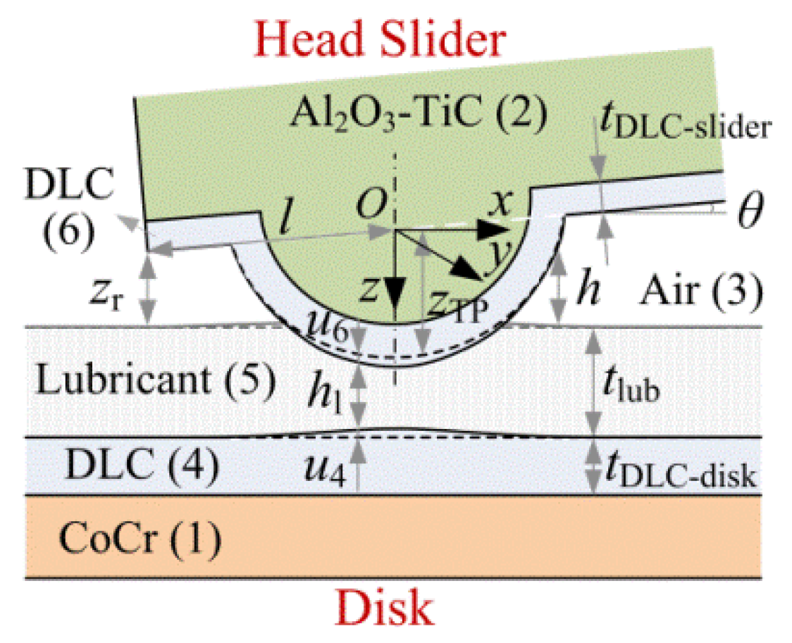
For the sake of computational efficiency, only the CoCr magnetic layer (layer 1) overlaid with layer 4 of DLC and layer 5 of lubricant is modelled, as presented in Figure 2. This model is reasonable, as reported by White [24] that the relative error of the vdW force per unit area predicted by the model considering the first two layers of the disk and that the full multilayered construction of the disk, is less than 10%. In regard to symbols in Figure 2, the layers of the slider and the medium air are numbered by 2, 6 and 3, respectively. The thicknesses of the DLC layer and the lubricant layer on the disk and the DLC layer on the slider are denoted as tDLC-disk, tlub and tDLC-slider, respectively. The coordinate system is established at the center of the TP, which is at a distance of l from the trailing edge of the slider. h stands for the distance between the slider surface and the disk lubricant layer, while h1 denotes the distance between the slider surface and the disk DLC layer. The minimum value of h (x, y) is the flying height FH, that is FH = min {h (x, y)}. zTP (x, y) represents the z coordinate of the undeformed DLC layer surface on the slider.
The net interaction force F at the HDI caused by the molecular interaction includes both the adhesion force Fa and the contact force Fc satisfying
F = F c F a
The contact force Fc is the integration of pressure P (x, y) in the contact zone Ωc between the slider and the disk, while the adhesion force Fa is the absolute value of the integration of pressure P (x, y) outside the contact area Ωa, which can be expressed, respectively, as
F c = Ω c P ( x , y ) d x d y
F a = Ω a P ( x , y ) d x d y
Pressure P (x, y) is the interaction force per unit area of the HDI, which is positive inside and negative outside of the contact zone and can be given by
P ( x , y ) = P vdW ( x , y ) + P rep ( x , y )
where Pvdw and Prep denote the vdW pressure and the repulsive pressure, respectively.
The vdW attractive interaction between macroscopic bodies can be obtained by the Lifshitz theory [22], as described in the introduction. The previous Lifshitz-based model [24,26], which constructed the relationship between the vdW pressure and the dielectric function for two parallel layered systems, can be extended to predict the vdW interaction between the TFC slider and the disk according to the Derjaguin approximation [27], as the local curvature radius of the TP is usually on the micron scale which is much larger than the nanometer-sized FH [8,19]. It is assumed that the equilibrium distance, at which the net interaction force vanishes, between two parallel surfaces having properties of the slider and the disk across the air gap is denoted by z01. If hz01, the slider flies away from the disk and the intermediate medium is air, while if h < z01, the TP is in contact with the lubricant or the DLC layer and the intermediate medium between the slider and the disk can be considered as lubricant. Whether the slider operates at the flying state, the TP–lube contact state or the TP–DLC contact state, the vdW pressure Pvdw can be uniformly expressed as
P vdW ( x , y ) = { k T 8 π h 3 n = 0 r n d r r 2 · [ Δ ¯ 31 E Δ ¯ 32 E e r 1 Δ ¯ 31 E Δ ¯ 32 E e r + Δ ¯ 31 F Δ ¯ 32 F e r 1 Δ ¯ 31 F Δ ¯ 32 F e r ] , ( a ) i f   h ( x , y ) z 01 k T 8 π h l 3 n = 0 r n d r r 2 · [ Δ ¯ 51 E Δ ¯ 52 E e r 1 Δ ¯ 51 E Δ ¯ 52 E e r + Δ ¯ 51 F Δ ¯ 52 F e r 1 Δ ¯ 51 F Δ ¯ 52 F e r ] , ( b ) i f   h ( x , y ) < z 01
where, k is the Boltzmann’s constant k = 1.38 × 10 −23 J/K and T is the absolute temperature T = 293.15 K. The prime on the summation indicates that the n = 0 term is assigned half weight [24].
In Equation (5a), Δ ¯ 31 E , Δ ¯ 32 E , Δ ¯ 31 F , Δ ¯ 32 F can be expressed as
Δ ¯ 31 E = Δ 35 E + Δ 54 E + Δ 41 E exp ( t D L C - d i s k s 4 / h ) 1 + Δ 54 E Δ 41 E exp ( t D L C - d i s k s 4 / h ) exp ( t lub s 5 / h ) 1 + Δ 35 E Δ 54 E + Δ 41 E exp ( t D L C - d i s k s 4 / h ) 1 + Δ 54 E Δ 41 E exp ( t D L C - d i s k s 4 / h ) exp ( t lub s 5 / h ) Δ ¯ 32 E = Δ 36 E + Δ 62 E exp ( t D L C - s l i d e r s 6 / h ) 1 + Δ 36 E Δ 62 E exp ( t D L C - s l i d e r s 6 / h ) Δ ¯ 31 F = Δ 35 F + Δ 54 F + Δ 41 F exp ( t D L C - d i s k s 4 / h ) 1 + Δ 54 F Δ 41 F exp ( t D L C - d i s k s 4 / h ) exp ( t lub s 5 / h ) 1 + Δ 35 F Δ 54 F + Δ 41 F exp ( t D L C - d i s k s 4 / h ) 1 + Δ 54 F Δ 41 F exp ( t D L C - d i s k s 4 / h ) exp ( t lub s 5 / h ) Δ ¯ 32 F = Δ 36 F + Δ 62 F exp ( t D L C - s l i d e r s 6 / h ) 1 + Δ 36 F Δ 62 F exp ( t D L C - s l i d e r s 6 / h )
where,
Δ i j E = ε i s j ε j s i ε i s j + ε j s i ,   Δ i j F = μ i s j μ j s i μ i s j + μ j s i s j = r 2 + r n 2 ( ε j ε 3 1 ) ,   r n = 2 h ξ n ε 3 c
where, c is the light speed c = 3 × 10⁸ m/s. εj = εj(n) and μj = μj(n) denote the dielectric permittivity and magnetic permeability of substance j evaluated at the imaginary frequency n. ξn = 0 and ξ0 ≈ 2.5 × 10¹⁴ rad/s at room temperature [24].
In Equation (5b), Δ ¯ 51 E , Δ ¯ 52 E , Δ ¯ 51 F , Δ ¯ 52 F are given by
Δ ¯ 51 E = Δ 54 E + Δ 41 E exp ( t D L C - d i s k s 4 / h l ) 1 + Δ 54 E Δ 41 E exp ( t D L C - d i s k s 4 / h l ) , Δ ¯ 52 E = Δ 56 E + Δ 62 E exp ( t D L C - s l i d e r s 6 / h l ) 1 + Δ 56 E Δ 62 E exp ( t D L C - s l i d e r s 6 / h l ) Δ ¯ 51 F = Δ 54 F + Δ 41 F exp ( t D L C - d i s k s 4 / h l ) 1 + Δ 54 F Δ 41 F exp ( t D L C - d i s k s 4 / h l ) , Δ ¯ 52 F = Δ 56 F + Δ 62 F exp ( t D L C - s l i d e r s 6 / h l ) 1 + Δ 56 F Δ 62 F exp ( t D L C - s l i d e r s 6 / h l )
where,
Δ i j E = ε i s j ε j s i ε i s j + ε j s i ,   Δ i j F = μ i s j μ j s i μ i s j + μ j s i s j = r 2 + r n 2 ( ε j ε 5 1 ) ,   r n = 2 h l ξ n ε 5 c
The repulsive interaction between molecules is a short-range interaction, which is less influenced by the adjacent atoms, and the pairwise additivity applies. Under the hypothesis that the lubricant layer does not affect the contact force and the solid contact area [28], the repulsive interaction force per unit area Prep at the HDI is written as [15]
P rep ( x , y ) = { B 45 π h 9 , i f   h ( x , y ) z 01 ( a ) B 45 π h 1 9 , i f   h ( x , y ) < z 01 ( b )
where B is a constant.
The influence of the TP–lube contact or the TP–DLC contact on the lubricant thickness is neglected. The same assumptions with Stanley’s study [28], that the force at the lubricant surface can be transmitted to the solid and the topography of the lubricant surface is the same as the solid surface, are made. According to the geometrical relationship shown in Figure 2, the following equations can be constructed.
h ( x , y ) = l sin θ + z r z T P ( x , y ) + u ( x , y )
h l ( x , y ) = h ( x , y ) + t lub
where u(x, y) = u4(x, y) + u6(x, y). u4(x, y) and u6(x, y) denote the surface elastic deformation in the z axis of the DLC layer on the disk and that of the DLC layer on the slider, respectively. It is stipulated that the deformation is positive if the disk deforms downward or the slider deforms upward, otherwise it is negative. The geometry of the TP is modeled approximately as an ellipsoid, as shown in Figure 3. la, lb and lc denote the three hemi-axial lengths of the ellipsoid. The coordinate (x, y, z) for the surface of the ellipsoidal TP satisfies the following equation.
( x cos θ z sin θ l a ) 2 + ( y l b ) 2 + ( x sin θ + z cos θ l c ) 2 = 1
Then, zTP(x, y) can be written as
z T P = { ( l c 2 l a 2 ) sin θ cos θ l c 2 sin 2 θ + l a 2 cos 2 θ x + l a 2 l b 2 l c 2 l a 2 l c 2 y 2 l b 2 ( l c 2 sin 2 θ + l a 2 cos 2 θ ) l a 2 l c 2 x 2 ( l c 2 sin 2 θ + l a 2 cos 2 θ ) 2 ,         i f l a 2 l b 2 l c 2 l a 2 l c 2 y 2 l b 2 ( l c 2 sin 2 θ + l a 2 cos 2 θ ) l a 2 l c 2 x 2 ( l c 2 sin 2 θ + l a 2 cos 2 θ ) 2 > 0 x tan θ ,     e l s e
Assuming that the contact zone is small compared with the size of the contact body, the elastic deformations u4(x, y) and u6(x, y) can be expressed as
u 4 ( x , y ) = g 4 ( x x , y y ) P ( x , y ) d x d y
u 6 ( x , y ) = g 6 ( x x , y y ) P ( x , y ) d x d y
where g4 and g6 denote the Green functions for the normal elastic deformation on the surface of the slider and that of the disk, respectively.

2.2. Numerical Method

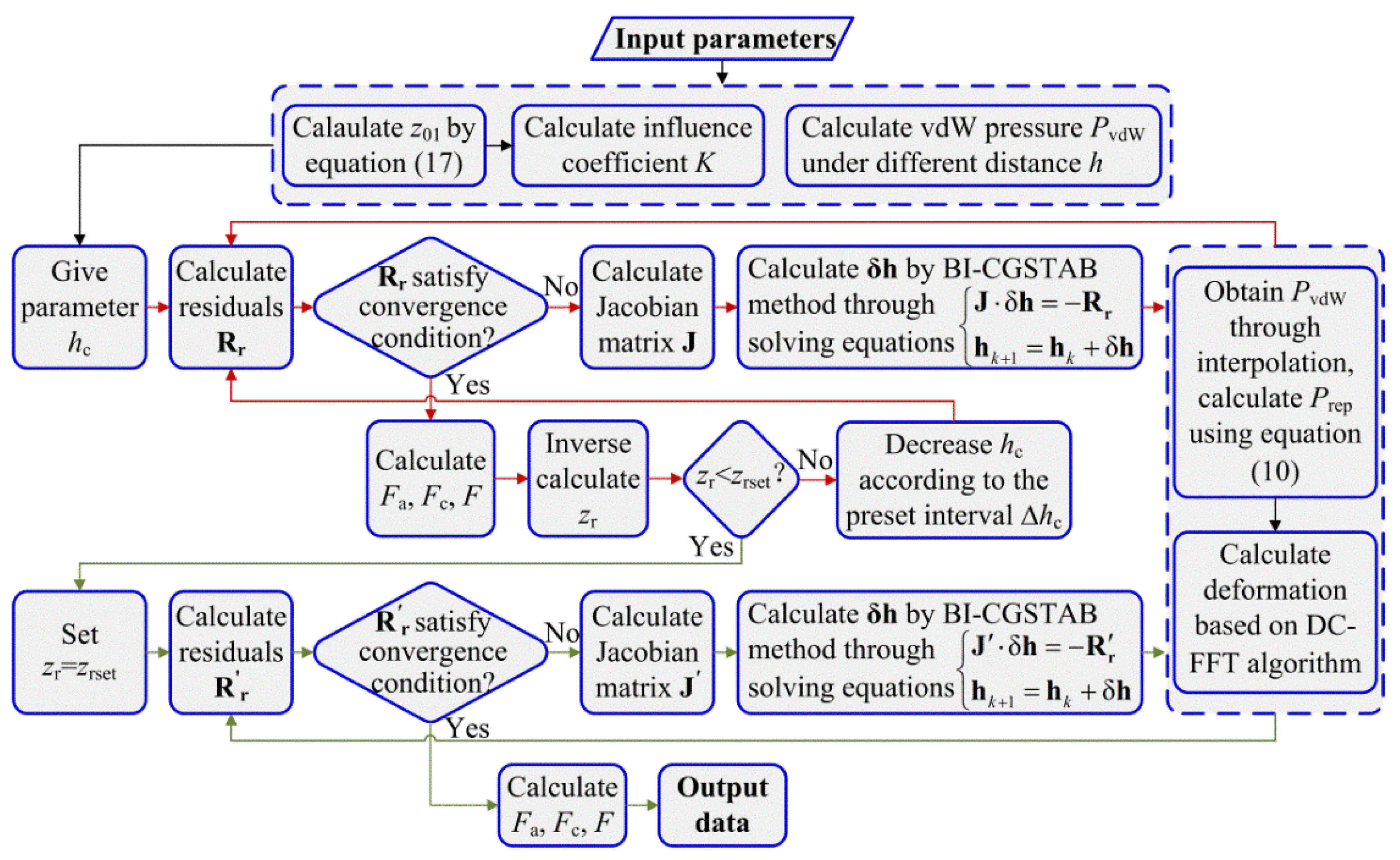
The analysis of adhesive interaction at the HDI requires the use of numerical methods for Equation (11). To improve the computational efficiency, the inexact Newton–Bi-conjugate stabilized method is applied, and the numerical procedure is given in Figure 4. The key techniques involved are introduced in the following.
(1) Determination of the equilibrium distance z01:
At the equilibrium distance, the net interaction force of two surfaces vanishes, which implies that PvdW + Prep = 0 at h = z01. Therefore, z01 satisfies
k T 8 π z 01 3 n = 0 r n d r r 2 · [ Δ ¯ 31 E Δ ¯ 32 E e r 1 Δ ¯ 31 E Δ ¯ 32 E e r + Δ ¯ 31 F Δ ¯ 32 F e r 1 Δ ¯ 31 F Δ ¯ 32 F e r ] + B 45 π z 01 9 = 0
The relaxation iterative method is used to solve the above equation.
(2) Determination of the vdW pressure Pvdw:
According to Equation (5), the vdW pressure is a two-dimensional summation operation, which is time-consuming in the numerical procedure of the Newton method. To reduce computational burdens, the vdW pressure at different distances is calculated at first and then used through interpolation during the iterative solving of Equation (11).
(3) Determination of the initial estimate of distance h:
For the Newton method, the initial value of h can influence the convergence of the iterative procedure. When the nominal flying height zr is larger compared with the TP height, the adhesive interaction at the HDI is small and the surface deformation can be neglected. Thus, h = lsinθ + zrzTP can be taken as the initial guess of h. However, with the decrease in the nominal flying height zr, the adhesive interaction becomes remarkable and the initial estimate of h should take the surface deformation into account. In addition, jump-in and jump-out instabilities [29] may occur at the HDI. Near the jump-in and jump-out points, small changes in the nominal flying height may lead to the abrupt variation of the interface interaction between the head and the disk, which will influence the convergence of the numerical simulation. To solve this problem, the nominal flying height is substituted by the distance h(0, 0). Denoting hc = h(0, 0), the following equation is derived from Equation (11).
h c = h ( 0 , 0 ) = l sin θ + z r z T P ( 0 , 0 ) + u ( 0 , 0 )
By combining Equation (11) with Equation (18), we have
h ( x , y ) = h c [ z T P ( x , y ) z T P ( 0 , 0 ) ] + [ u ( x , y ) u ( 0 , 0 ) ]
Through the above substitution, the distance h becomes a function of the central distance hc. To obtain the initial value of h at a preset nominal flying height zrset, the simulation procedure starts from a large central distance hc and solves Equation (19) using an initial value h = hc − [zTP(x, y) − zTP(0, 0)]. After achieving the convergent solution, zr can be inversely calculated by Equation (18). If zr < zrset, then the central distance is decreased by a preset interval Δhc, and the existing solution at hc is used as the initial estimate at hc − Δhc. The above process is repeated until the condition zr < zrset does not satisfy. Using the obtained solution as the initial guess at zr = zrset, and solving Equation (11), the desirable convergent solution can be acquired. The detailed flowchart for the computational procedure is presented in Figure 4, and the element of residuals Rr, Rr′ and that of the Jacobian Matrix J, J′ in discrete form can be written as
R r i j = h i j h c + ( z T P i j z T P i c j c ) ( u i j u i c j c ) ( a ) J i j I J = R r i j h I J = δ i j I J ( K I J i j K I J i c j c ) P I J h I J ( b ) R r i j = h i j l sin θ z r + z T P i j u i j ( c ) J i j I J = R r i j h I J = δ i j I J K I J i j P I J h I J ( d ) ( δ i j I J = { 1 , i f   i = I   a n d   j = J 0 , e l s e )
where i, I = 0:M, and j, J = 0:N. M and N are the total numbers of mesh points in x and y directions. ic and jc stand for the grid nodes at x = 0 and y = 0, respectively. K I J i j = K 4 I J i j + K 6 I J i j , in which K4 and K6 denote the influence coefficients for the elastic deformation due to pressure on the surface of the slider and that of the disk, respectively.
(4) Determination of the elastic deformations u4 and u6:
For the layered structure, the Green function for the elastic deformation in the spatial domain is difficult to be derived; however, its frequency response function in the frequency domain can be obtained in light of the Papkovich–Neuber potentials, continuity condition at the layer/substrate interface and boundary conditions at the contact surface. Details can be referred to in the study of Liu [30].
Discrete forms of the elastic deformations u4 and u6 can be expressed as
u 4 ( x i , y j ) = I = 0 M J = 0 N K 4 I J i j P I J
u 6 ( x i , y j ) = I = 0 M J = 0 N K 6 I J i j P I J
The influence coefficients K4 and K6 can be derived from the frequency response functions g ˜ ˜ 4 and g ˜ ˜ 6 based on the convolution theorem and the fast Fourier Transform technique [30]. Then, the elastic deformations can be solved according to Equations (21) and (22) through the DC-FFT (Discrete convolution and fast Fourier transform) algorithm [30].

3. Results and Discussions

For the simulations in this paper, layers contained in the simplified HDI have the material properties shown in Table 1. The dielectric functions εj(n) shown in Ref. [24] are used and the magnetic permeability μj is equal to 1. The constant B is taken to be 10−76 J·m6 [15]. Parameters related with TP and the thickness of layers are l = 8 μm, θ = 10−4 rad, tDLC-disk = 0.5~3 nm, tlub = 0.5~3 nm, tDLC-slider = 1~2 nm, la = 2 μm, lb = 10 μm, lc = 5~13 nm. For the TFC slider, the interaction at the HDI is mainly determined by the interaction between the TP and the disk. Therefore, for the sake of computational efficiency, the calculation domain is set to be −1.5lax ≤ 1.5la and −1.5lby ≤ 1.5lb, and the mesh numbers are 512 × 512.

3.1. Comparisons of Results Between Hamaker Theory and Lifshitz Theory

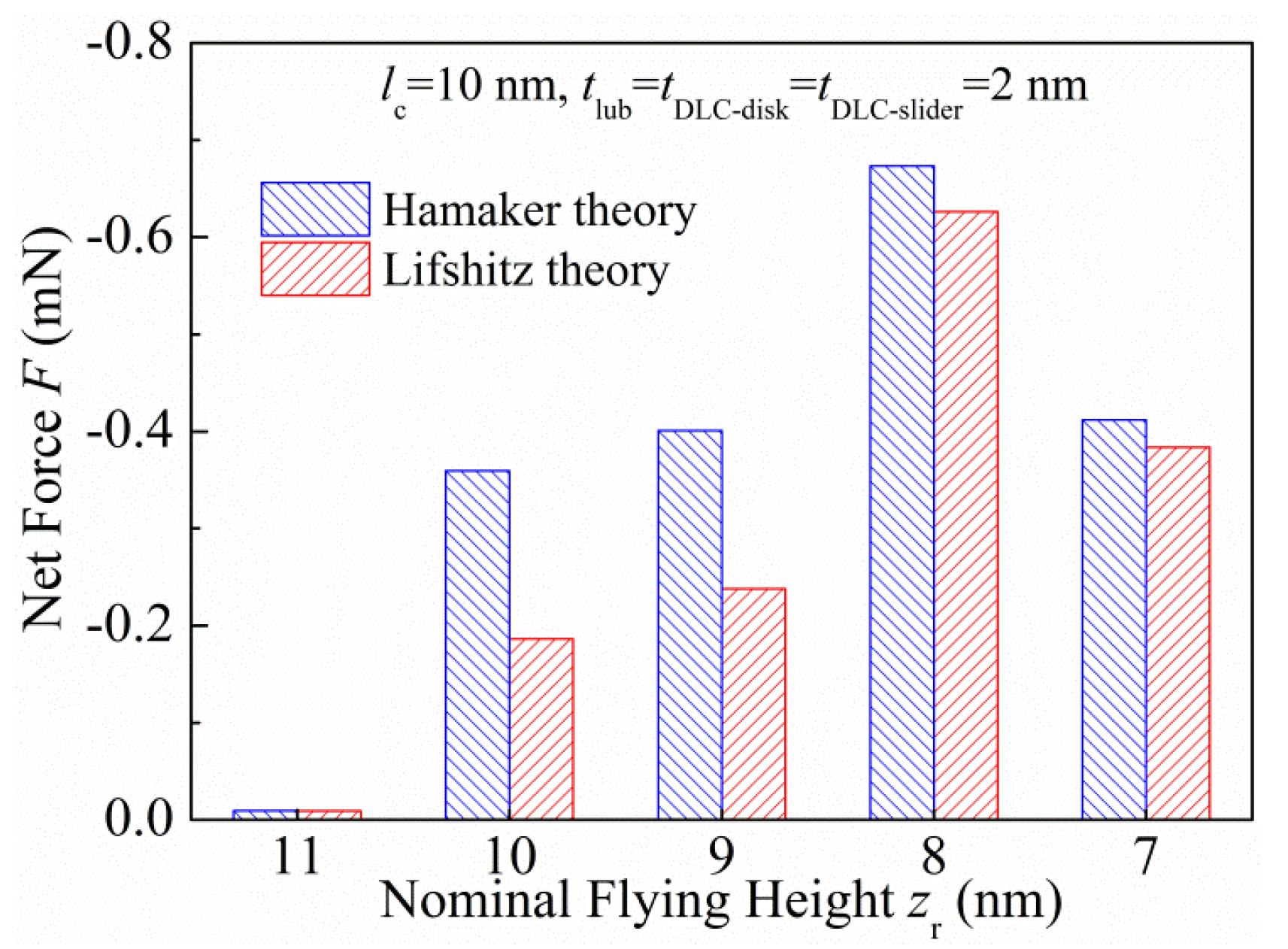
To obtain a qualitative understanding of the difference between the Hamaker theory and the Lifshitz theory, Figure 5 compares the net force in terms of the nominal flying height. The vdW pressure in Hamaker theory is calculated by PvdW = -AH/(6h3), in which AH is the Hamaker constant and a typical value of AH = 10−19 J [15] is assumed in the present study. Discrepancies are found between results predicted by these two theories, implying that it is unreasonable to set a value of the Hamaker constant directly.

3.2. Analysis of The Adhesive Contact Characteristics at The HDI

To illustrate the adhesive contact characteristics of the HDI, Figure 6 shows a schematic of the adhesion force Fa, contact force Fc, net force F and flying height FH as a function of the nominal flying height zr. In regard to the results of this figure, five sub-regions, I–V, can be divided. In region I, the slider flies sufficiently away from the disk, and the net force depends entirely on the adhesion force as no contact occurs. In this region, the magnitude of the net force (|F|) increases and the FH decreases with the nominal flying height. When the nominal flying height decreases to the value at point A in region II, the attractive interaction increases abruptly and the TP jumps into contact with the lubricant, as evidenced by the sudden decrease in FH to the equilibrium distance z01. If the nominal flying height is now increased, the net force follows the A’B branch as far as point B but then jumps to point B’, implying that the TP jumps out of contact with the lubricant. In region III, the slider is at the TP–lube contact state, and the net force is still determined totally by the adhesion force. As the nominal flying height decreases, it causes the magnitude of the net force to increase accompanied by a decrease in the FH. In region IV, the TP jumps from point C to point C’, at which it comes into contact with the DLC layer and the FH decreases to z02-tlub, and jumps out of contact from point D to point D’. z02 stands for the equilibrium distance between two parallel surfaces having properties of the slider and the disk across the lubricant. In region V, the slider is at the TP–DLC contact state. During this full contact regime, both the adhesion force and the contact force increase with the decreasing nominal flying height, while the FH is almost unchangeable. Due to the combined effect of the adhesion force and the contact force, the magnitude of the net force increases firstly until reaching a maximum value and then decreases.
Three important results can be extracted from the above contact characteristics of the HDI. First, the operation status of the slider can be approximately determined in light of the FH. The slider is at the flying state when FH > z01, at the TP–lube contact state when z02-tlub < FHz01, and at the TP–DLC contact state when FHz02-tlub. Second, jump-in and jump-out phenomena occur in regions II and IV, which can influence the stability of the slider and should be avoided during the operation of the HDD. Third, at the TP–DLC contact state, the adhesive interaction is remarkable compared with that at the flying or TP–lube contact states. The FH is difficult to be reduced further due to the strong repulsive interaction of the HDI at the small distance.
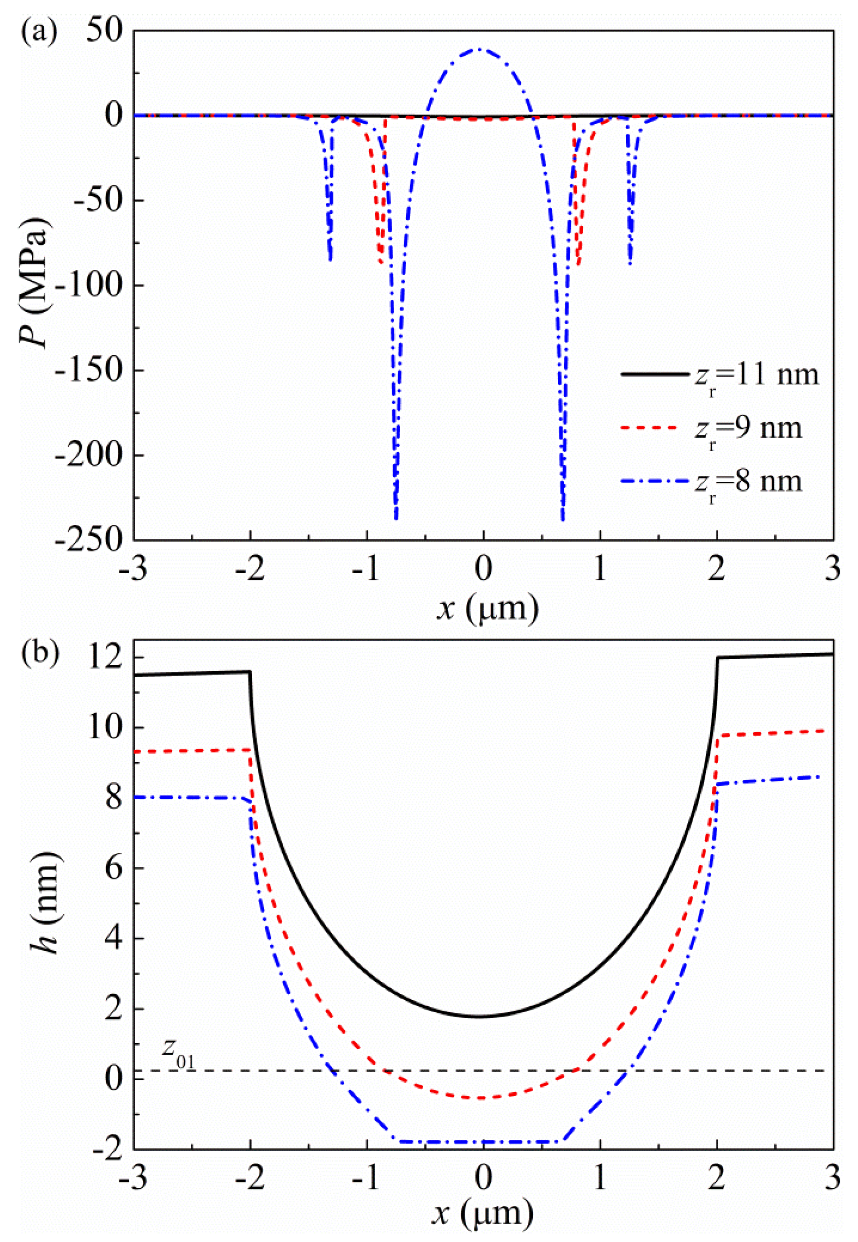
The distribution of interaction pressure P for three nominal flying heights zr = 11 nm, 9 nm and 8 nm corresponding to the flying state, the TP–lube contact state and the TP–DLC contact state is shown in Figure 7 in conjunction with the distance h in the section of y = 0. It can be seen that the pressure is almost zero and the surface is basically undeformed at the flying state (for example zr = 11 nm). When the TP is in contact with the lubricant (for example zr = 9 nm), the adhesive interaction near the contact edge between the TP and the lubricant becomes remarkable. At the TP–DLC contact state (for example zr = 8 nm), the local pressure is positive at the contact center, together with the obvious surface deformation. Furthermore, strong attractive interactions near the TP–DLC contact edge and near the periphery of the TP–lube contact zone are observed. The direct contact between the TP and the disk can exacerbate the wear of the slider and/or the disk.

3.3. Effects of TP Height on the Interaction Force and FH at the HDI

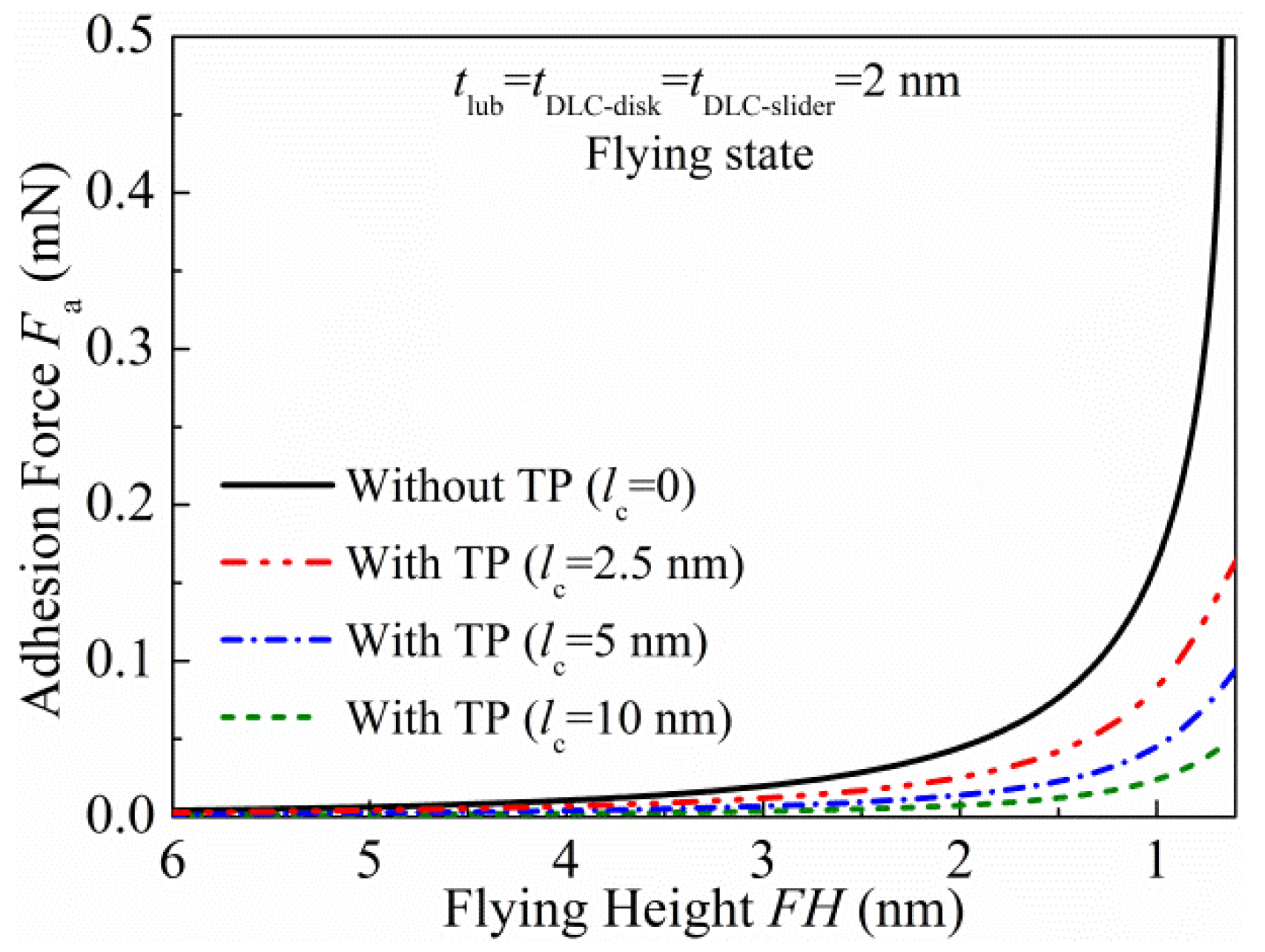
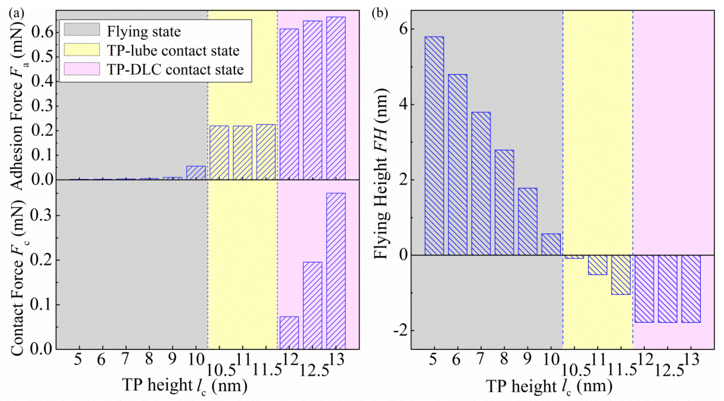
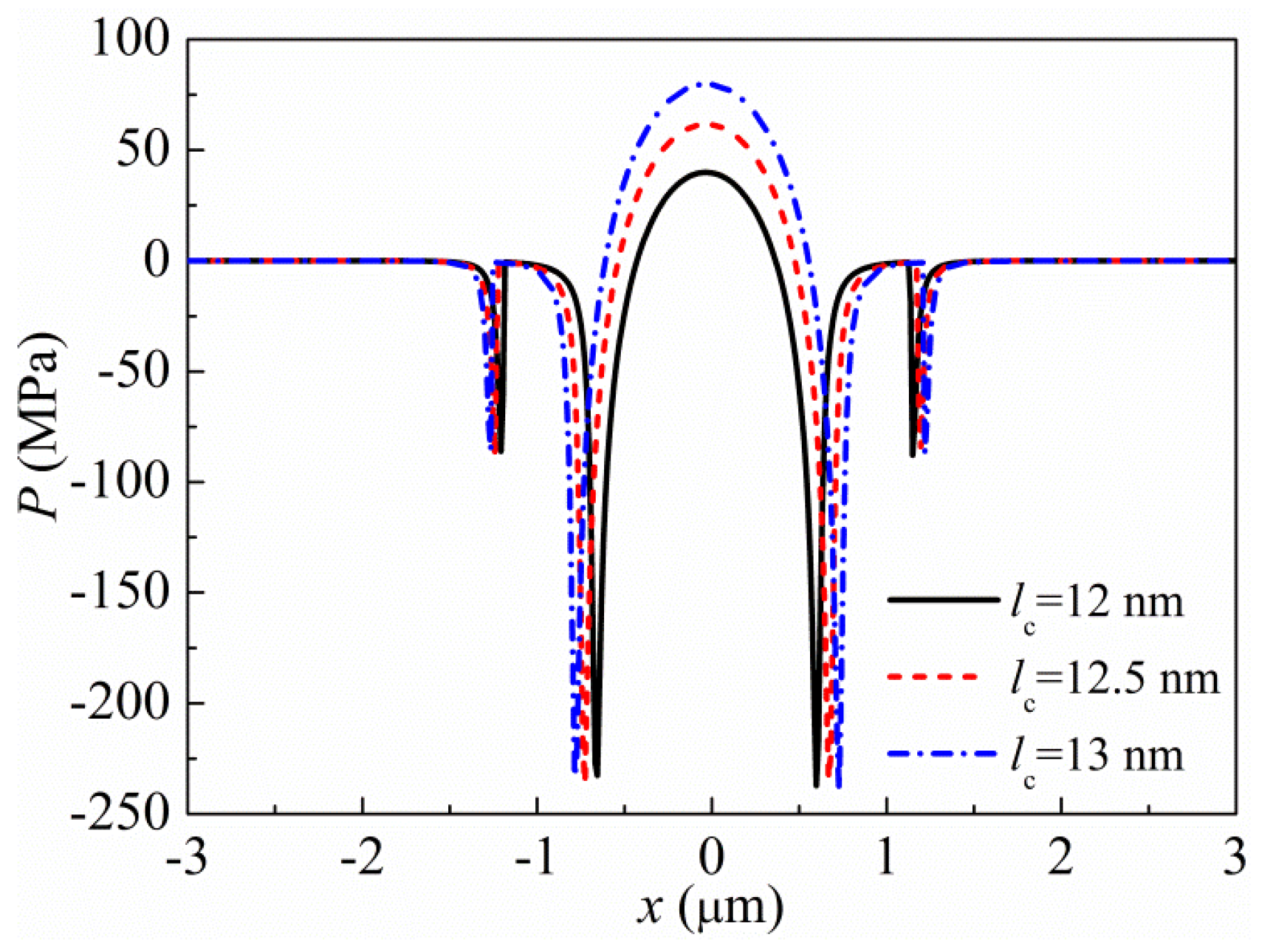
The adhesion forces of the HDI without TP and that with TP having different heights when the slider is at the flying height are compared in Figure 8. It should be noted that the FH is equal to the nominal flying height zr for the case of HDI without using the TFC technology. It is observed that the adhesion force at the HDI without TP is larger than that at the HDI with TP, and this discrepancy is more remarkable when the FH becomes smaller, demonstrating the necessity of using the TFC technology at ultra-low flying heights. The effects of the TP height on the adhesion force, contact force and FH at a fixed nominal flying height are presented in Figure 9. Transitions of the slider operation state from the flying state (the left grey region) to the TP–lube contact state (the middle yellow region) and then to the TP–DLC contact state (the right pink region) with the increase in the TP height are observed. During the flying state, the adhesion force increases and the FH decreases if the TP height is increased. When the TP comes into contact with the lubricant, the increased TP height results in a decreased FH and an almost unchangeable adhesion force. If the slider is at the TP–DLC contact state, the adhesion force and contact force increase but the FH cannot be obviously reduced by increasing the TP height on one hand, and on the other hand, the contact zone and contact pressure increase, as depicted in Figure 10. The increase in the contact pressure and contact zone can affect the friction and wear of the HDI and, as a result, may influence the read/write accuracy. Therefore, excessive TP height should be avoided.

3.4. Effects of Lubricant Thickness on the Interaction Force and HMS at the HDI

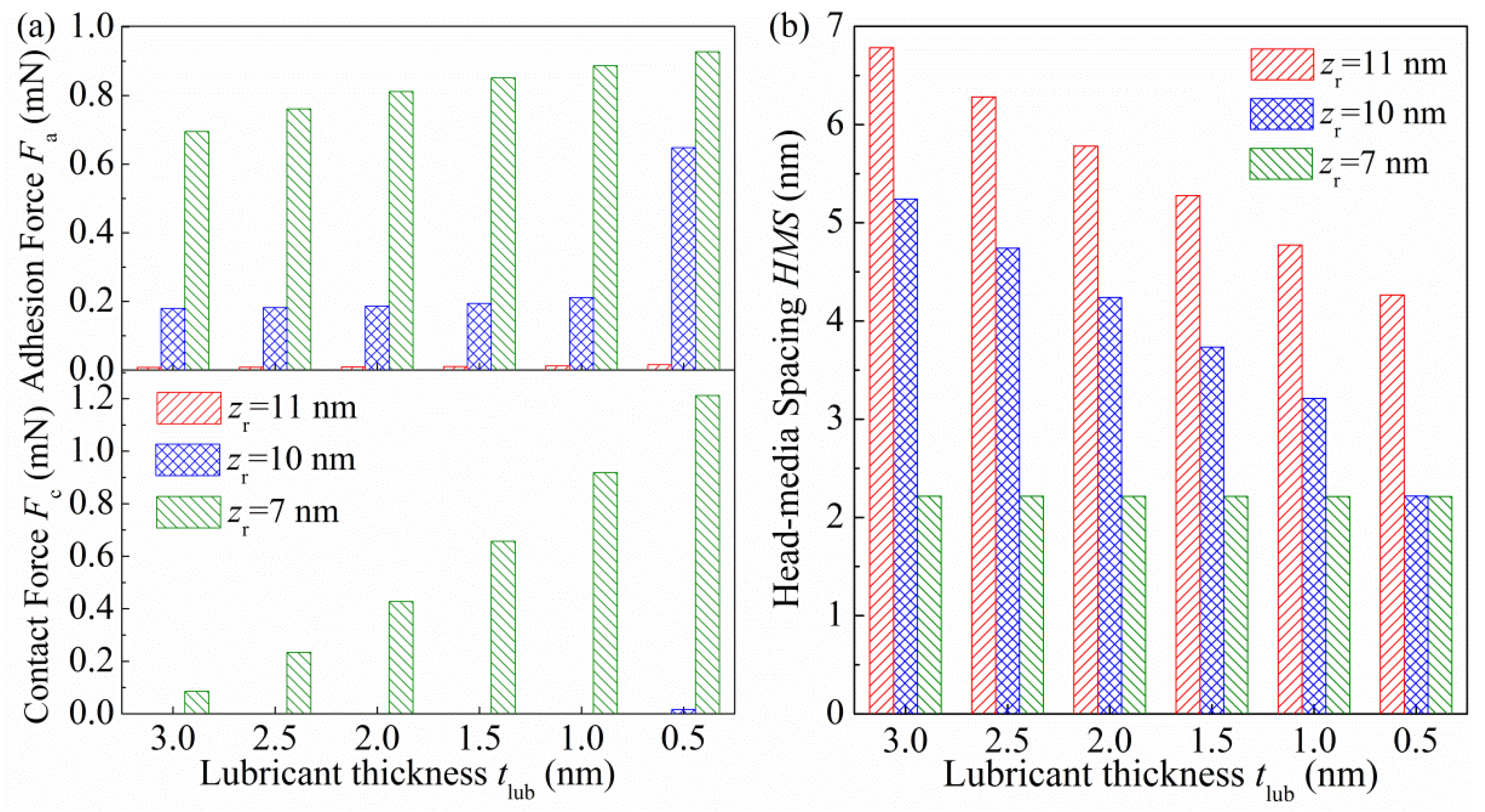
The lubricant thickness not only influences the head–media spacing (HMS) through changing the FH, but, in addition, can itself affect the magnitude of HMS. Therefore, in the interpretation of effects of the lubricant thickness, Figure 11 shows variations of the adhesion force, contact force and HMS as a function of the lubricant thickness, for zr = 11 nm, 10 nm and 7 nm, respectively. At zr = 11 nm, the slider is at the flying state over the entire range of the investigated lubricant thickness. A decrease in the HMS and slight increase in the adhesion force with the decreasing lubricant thickness are found. When zr = 10 nm, the TP is in contact with the lubricant at 1 nm ≤ tlub ≤ 3 nm, at which the variation trends of the HMS and adhesion force with the lubricant thickness are the same as for the case of the flying state. However, if tlub < 1 nm, the adhesion force increases remarkably because of the contact between the TP and the DLC layer. From the perspective of avoiding large adhesion force, the lubricant thickness should not be small. When zr = 7 nm, the slider operates at the TP–DLC contact state for the lubricant thickness ranging from 0.5 nm to 3 nm. It is found that the HMS cannot be reduced further through decreasing the lubricant thickness.

3.5. Effects of DLC Thickness on the Interaction Force and HMS at the HDI

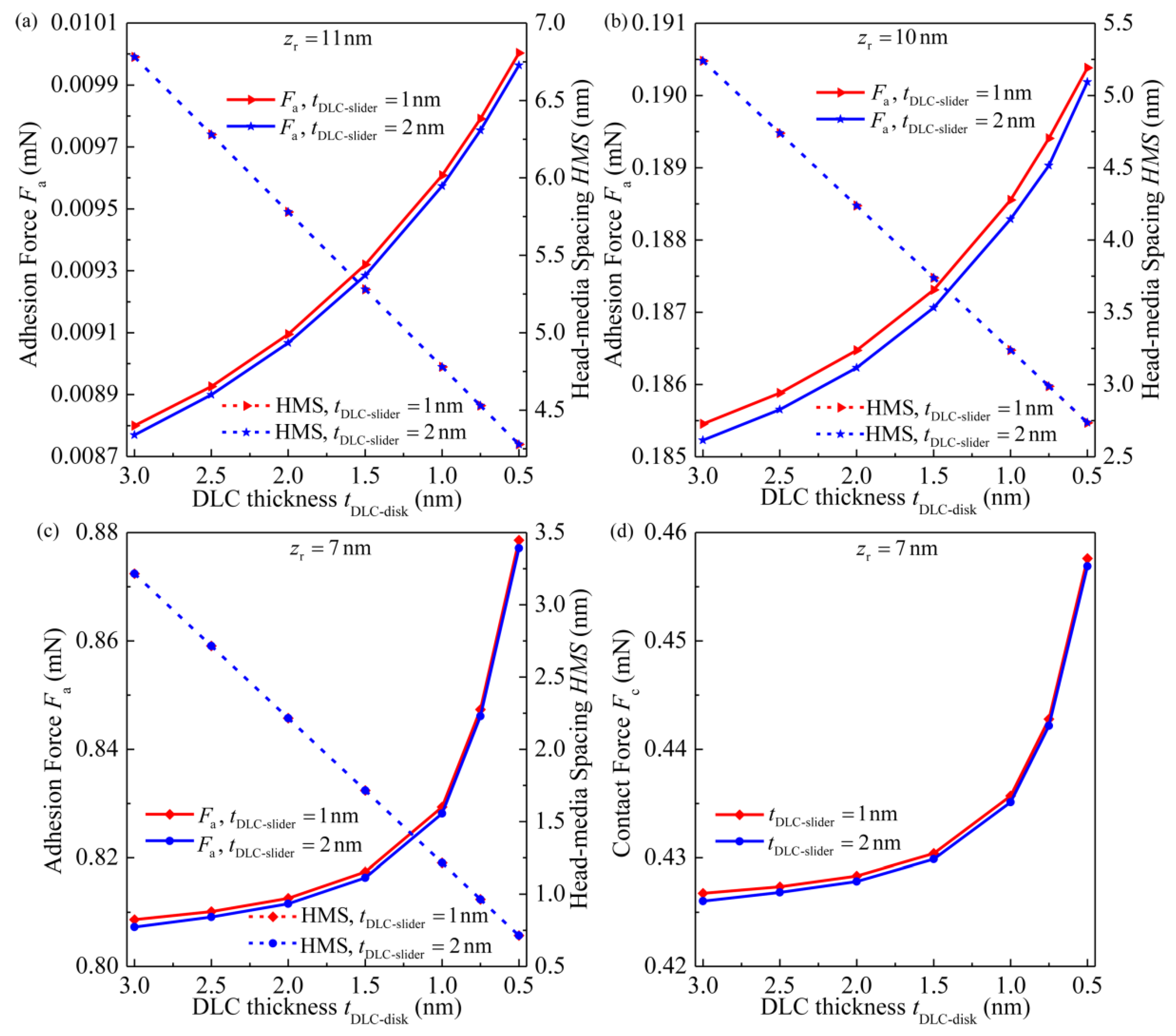
The magnitude of the DLC thickness is also of importance in regard to the adhesion and HMS of the HDI. To illustrate the influence of the DLC thickness, Figure 12 demonstrates results of the adhesion force, contact force and HMS. Three nominal flying heights of 11 nm, 10 nm and 7 nm, corresponding to the flying state, TP–lube contact state and TP–DLC contact state of the slider, are chosen. In Figure 12a–c, it is observed that the adhesion force is larger and the HMS is smaller for smaller DLC thicknesses on the disk in spite of the operation states. In addition, the contact force that presents during the TP–DLC contact state increases with the decreasing DLC thickness on the disk, as depicted in Figure 12d. It is also found, by comparing the results when the DLC thickness of the slider equals to 1 nm and 2 nm, that a smaller DLC thickness of the slider yields a larger adhesion force and an almost unchangeable HMS. Hence, a relatively thick layer is more beneficial since it reduces the adhesion of the HDI.

4. Conclusions

A numerical adhesive contact model for the TFC slider–disk interface based on the Lifshitz theory, capable of handling various recording status including the flying state, lubricant contact state and solid contact state, is established in this paper. The adhesive contact characteristics of the HDI in the presence of thin lubricant and DLC layers are examined, and effects of the TP height, lubricant thickness and DLC thickness on the interaction force and FH (or HMS) are investigated. The main conclusions are as follows.
(1) Unstable regions exist when the status of the slider transits from the flying state to the TP–lube contact state and from the TP–lube contact state to the TP–DLC contact state, which should be avoided in the operation of the HDD.
(2) At the TP–DLC contact state, adhesive interactions occur near the TP–DLC contact edge and near the periphery of the TP–lube contact zone, which are more remarkable than those at the flying state or the TP–lube contact state. At the TP–DLC contact center, strong repulsive interactions exhibit when the TP comes into proximity with the disk and the FH is difficult to be further reduced.
(3) The adhesion force of the HDI using the TFC technology is smaller than that without applying the TFC technology under the same FH at the flying state.
(4) Under the fixed nominal flying height, the FH can be reduced through suitably increasing the TP height at the flying state or the TP–lube contact state with only a slight increase in the adhesion force. However, at the TP–DLC contact state, increasing the TP height can not only render the FH almost unchangeable, but also increase the contact force and contact zone which influence the friction and wear properties of the HDI.
(5) The HMS can be reduced by decreasing the lubricant thickness when the slider operates under the flying state or the TP–lube contact state, while, at the TP–DLC contact state, the HMS cannot be further reduced through decreasing the lubricant thickness.
(6) The decrease in the DLC thickness on the disk is beneficial in reducing the HMS, but can increase the adhesive interaction of the HDI. The thickness of the DLC layer on the slider has negligible effects on the HMS, thus a relatively thick layer is more beneficial since it reduces the adhesion at the HDI.

Author Contributions

Conceptualization, Y.Z. and W.Y.; Methodology, Y.Z.; Software, L.J.; Validation, W.Y.; Formal Analysis, Q.Y.; Investigation, Y.Z.; Resources, W.Y.; Data Curation, C.M.; Writing—Original Draft Preparation, Y.Z.; Writing—Review and Editing, C.M.; Visualization, L.J.; Supervision, Q.Y.; Project Administration, C.M.; Funding Acquisition, Y.Z. and W.Y. All authors have read and agreed to the published version of the manuscript.

Funding

The authors would like to express their gratitude to the financial support from the National Natural Science Foundation of China (No. 51805269), the Youth Science and Technology Innovation Foundation of Nanjing Forestry University (No. CX2017007), and the Postdoctoral Foundation of China (No. 2019M660449).

Conflicts of Interest

The authors declare no conflict of interest.

References

  1. Dawit, Z.S.; Polina, V.K.; Pyung, H. Experimental and direct numerical analysis of hard-disk drive. J. Mech. Sci. Technol. 2018, 32, 3507–3513. [Google Scholar]
  2. Samad, M.A.; Rismani, E.; Yang, H.; Sinha, S.K.; Bhatia, C.S. Overcoat Free Magnetic Media for Lower Magnetic Spacing and Improved Tribological Properties for Higher Areal Densities. Tribol. Lett. 2011, 43, 247–256. [Google Scholar] [CrossRef]
  3. Marchon, B.; Pitchford, T.; Hsia, Y.-T.; Gangopadhyay, S. The Head-Disk Interface Roadmap to an Areal Density of Tbit/in2. Adv. Tribol. 2013, 2013, 1–8. [Google Scholar] [CrossRef] [Green Version]
  4. Katta, R.R.; Polycarpou, A.A. Microtribodynamics of Magnetic Storage Hard Disk Drives; Springer Science and Business Media LLC: New York, NY, USA, 2013; pp. 2244–2256. [Google Scholar]
  5. Vakis, A.I.; Polycarpou, A.A. Head-disk interface nanotribology for Tbit/inch2recording densities: Near-contact and contact recording. J. Phys. D Appl. Phys. 2010, 43, 225301. [Google Scholar] [CrossRef]
  6. Schultz, B.E. Thermal fly-height control (TFC) technology in Hitachi hard disk drives. Hitachi Glob. Storage Technol. San Jose 2007, 1–4. [Google Scholar]
  7. Hua, W.; Liu, B.; Yu, S.; Zhou, W. Contact recording review. Microsyst. Technol. 2010, 16, 493–503. [Google Scholar] [CrossRef]
  8. Vakis, A.I.; Polycarpou, A.A. Optimization of thermal fly-height control slider geometry for Tbit/in2 recording. Microsyst. Technol. 2010, 16, 1021–1034. [Google Scholar] [CrossRef]
  9. Ono, K. Effect of van der Waals Forces in a Near Contact Head-Disk Interface. IEEE Trans. Magn. 2008, 44, 3675–3678. [Google Scholar] [CrossRef]
  10. Suh, A.Y.; Polycarpou, A.A. Adhesive contact modeling for sub-5-nm ultralow flying magnetic storage head-disk interfaces including roughness effects. J. Appl. Phys. 2005, 97, 104328. [Google Scholar] [CrossRef]
  11. Liu, B.; Zhang, M.; Yu, S.; Hua, W.; Wong, C.H.; Zhou, W.; Man, Y.; Gonzaga, L.; Ma, Y. Towards fly- and lubricant-contact recording. J. Magn. Magn. Mater. 2008, 320, 3183–3188. [Google Scholar] [CrossRef]
  12. Man, Y.; Liu, B.; Ng, K.K.; Yu, S.; Sinha, S.K.; Lim, S.C. Investigations of Light Contact and Lube-Surfing State with Electrical Current. IEEE Trans. Magn. 2014, 50, 1–4. [Google Scholar] [CrossRef]
  13. Israelachvili, J.N. Intermolecular and Surface Forces, 3rd ed.; Elsevier: Santa Barbara, CA, USA, 2011. [Google Scholar]
  14. Hamaker, H. The London—van der Waals attraction between spherical particles. Physica 1937, 4, 1058–1072. [Google Scholar] [CrossRef]
  15. Wu, L.; Bogy, D.B. Effect of the Intermolecular Forces on the Flying Attitude of Sub-5 NM Flying Height Air Bearing Sliders in Hard Disk Drives. J. Tribol. 2002, 124, 562–567. [Google Scholar] [CrossRef]
  16. Trinh, T.D. Tribological Performance of the Head-Disk Interface in Perpendicular Magnetic Recording and Heat-Assisted Magnetic Recording. Ph.D. Thesis, University of California, San Diego, CA, USA, 2019. [Google Scholar]
  17. Yu, N.; Polycarpou, A.A. Adhesive contact based on the Lennard–Jones potential: A correction to the value of the equilibrium distance as used in the potential. J. Colloid Interface Sci. 2004, 278, 428–435. [Google Scholar] [CrossRef] [PubMed]
  18. Prokopovich, P.; Starov, V. Adhesion models: From single to multiple asperity contacts. Adv. Colloid Interface Sci. 2011, 168, 210–222. [Google Scholar] [CrossRef]
  19. Matthes, L.M.; Brunner, R.; Knigge, B.; Talke, F.E. Head Wear of Thermal Flying Height Control Sliders as a Function of Bonded Lubricant Ratio, Temperature, and Relative Humidity. Tribol. Lett. 2015, 60, 1–10. [Google Scholar] [CrossRef]
  20. Brunner, R.; Tyndall, G.W.; Waltman, R.J.; Talke, F.E. Adhesion Between Surfaces Separated by Molecularly Thin Perfluoropolyether Films. Tribol. Lett. 2010, 40, 41–48. [Google Scholar] [CrossRef] [Green Version]
  21. Lai, T.; Huang, P.; Cai, Y. Adhesion Reduction of Diamond-Like Carbon Films Based on Different Contact Geometries by Using an AFM. J. Adhes. 2014, 92, 18–38. [Google Scholar] [CrossRef]
  22. Lifshitz, E.; Hamermesh, M. The theory of molecular attractive forces between solids. Perspect. Theor. Phys. 1992, 2, 329–349. [Google Scholar] [CrossRef]
  23. Ninham, B.W.; Parsegian, V.A. van der Waals Interactions in Multilayer Systems. J. Chem. Phys. 1970, 53, 3398–3402. [Google Scholar] [CrossRef]
  24. White, L.R.; Dagastine, R.R.; Jones, P.M.; Hsia, Y.-T. van der Waals force calculation between laminated media, pertinent to the magnetic storage head-disk interface. J. Appl. Phys. 2005, 97, 104503. [Google Scholar] [CrossRef]
  25. Peng, W.; Crone, R.M.; Jones, P.M.; Hsia, Y.T. Effect of van der Waals force on air-bearing flying characteristics at ultra-low fly heigh. IEEE Trans. Magn. 2006, 42, 2483–2485. [Google Scholar] [CrossRef]
  26. Dagastine, R.R.; Bevan, M.; White, L.R.; Prieve, D.C. Calculation of van der Waals Forces with Diffuse Coatings: Applications to Roughness and Adsorbed Polymers. J. Adhes. 2004, 80, 365–394. [Google Scholar] [CrossRef]
  27. Derjaguin, V.B. Theorie des Anhaftens kleiner Teilchen. Prog. Surf. Sci. 1992, 40, 6–15. [Google Scholar] [CrossRef]
  28. Stanley, H.M.; Etsion, I.; Bogy, D.B. Adhesion of Contacting Rough Surfaces in the Presence of Sub-Boundary Lubrication. J. Tribol. 1990, 112, 98–104. [Google Scholar] [CrossRef]
  29. Wu, J.-J. Numerical analyses on elliptical adhesive contact. J. Phys. D Appl. Phys. 2006, 39, 1899–1907. [Google Scholar] [CrossRef]
  30. Liu, S.; Wang, Q. Studying Contact Stress Fields Caused by Surface Tractions with a Discrete Convolution and Fast Fourier Transform Algorithm. J. Tribol. 2001, 124, 36–45. [Google Scholar] [CrossRef] [Green Version]
  31. Yu, N.; Polycarpou, A.A.; Hanchi, J.V. Elastic contact mechanics-based contact and flash temperature analysis of impact-induced head disk interface damage. Microsyst. Technol. 2007, 14, 215–227. [Google Scholar] [CrossRef]
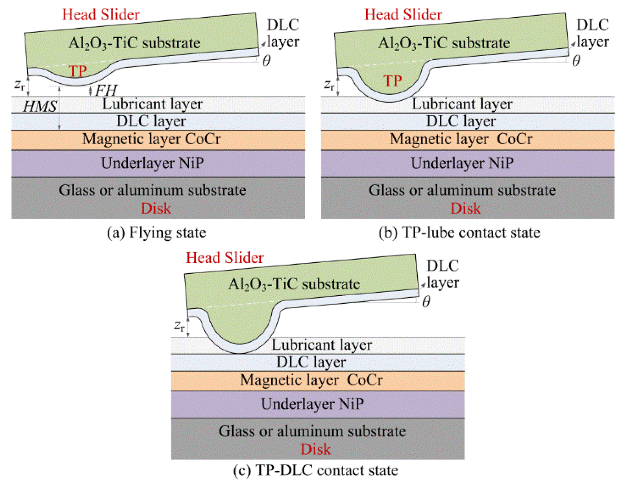
Figure 1. Schematic showing of the head–disk interface (HDI): (a) Flying state, (b) Thermal protrusion–lubricant (TP–lube) contact state, and (c) Thermal protrusion–diamond–like carbon (TP–DLC) contact state.
Applsci 10 05899 g001
Figure 2. Illustration of the adhesive contact for the simplified HDI.
Applsci 10 05899 g002
Figure 3. Ellipsoidal approximation of the TP geometry.
Applsci 10 05899 g003
Figure 4. Flowchart for the computational procedure.
Applsci 10 05899 g004
Figure 5. Comparisons of the net force predicted by the Lifshitz theory and the Hamaker theory.
Applsci 10 05899 g005
Figure 6. Variations of force and flying height with the nominal flying height under lc = 10 nm, tlub = tDLC-disk = tDLC-slider = 2 nm: (a) Adhesion force Fa, Contact force Fc, Net force F and (b) Flying height FH.
Applsci 10 05899 g006
Figure 7. Pressure and distance distributions in the section of y = 0 at different operation states under lc = 10 nm, tlub = tDLC-disk = tDLC-slider = 2 nm: (a) Pressure P and (b) Height h.
Applsci 10 05899 g007
Figure 8. Effects of TP on the adhesion force under different flying height FH.
Applsci 10 05899 g008
Figure 9. Force and flying height versus TP height under tlub = tDLC-disk = tDLC-slider = 2 nm, zr = 10 nm: (a) Adhesion force Fa, Contact force Fc and (b) Flying height FH.
Applsci 10 05899 g009
Figure 10. Pressure distribution in the section of y = 0 for different TP heights under tlub = tDLC-disk = tDLC-slider = 2 nm, zr = 10 nm.
Applsci 10 05899 g010
Figure 11. Force and head–media spacing versus the lubricant thickness under tDLC-disk = tDLC-slider = 2 nm: (a) Adhesion force Fa, Contact force Fc and (b) Head-media spacing HMS.
Applsci 10 05899 g011
Figure 12. DLC thickness versus adhesion force and HMS for (a) flying height of 11 nm; (b) flying height of 10 nm; (c) flying height of 7 nm; (d) DLC thickness versus contact force for flying height of 7 nm, under lc = 10 nm, tlub = 2 nm.
Applsci 10 05899 g012
Table 1. Material parameters [5,31].
MaterialElastic Modulus (GPa)Possion Ratio
CoCr1300.3
DLC2800.24
Al2O3-TiC4500.3