3.2. Load Resistance and Failure Modes
Typical deformation of a NCLT test specimen is shown in
Figure 8. The mid-span displacement of specimen 2 was the smallest, yet exceeded 100 mm; specimen 5 had the largest displacement at mid-span, exceeding 130 mm, far beyond the floor deformation limit of L/200 according to the Chinese Standard GB 50010-2002 [
19] under normal use conditions, indicating that NCLT panels have very large deformation capacity. The failure mode of specimens was primarily through tensile failure of the panel in the extreme tension zone, while the horizontally pressed wooden panels did not undergo failure. The test specimens exhibited overall ductile behavior. Damage of specimens originated from weak links in the tension zone, such as wood knots and defects, which caused stress concentration, leading to crack initiation and growth. Such cracks further developed into diagonal shape, which eventually caused the veneer to be broken. Some specimens warped in the width direction during processing, which resulted in larger gap between plates. As a result, the depth at which the nails were nailed into the wood decreased, and the nail force between the layers weakened. It was also observed that threaded nails in NCLT panels pulled out. Damage then occurred right at the part where the nails were pulled out, indicating that the pullout force of the threaded nails needed to be strengthened, for instance by increasing the nail diameter. When using veneers, previous experience with conventional CLT panels showed that they exhibited slippage and rolling shear. However, NCLT panels in this study experienced no slippage or rolling shear, demonstrating that the interlaminar combination and integrity can be largely improved by using nail connections rather than glue.
3.4. Ultimate Bending Capacity
FP Innovation theory system refers to the simplified theoretical analysis of conventional CLT panels of Canada’s FP Innovation: mechanical connection theory and combined K-factor theory [
20]. Mechanical connection theory and European standard “Eurocode 5” [
21] were combined, thus the maximum bending stress in the CLT panels can be considered as:
is the overall stress and can be calculated by Equation (2):
is the local stress and can be calculated by Equation (3):
In Equations (2) and (3):
γ is the connection coefficient (0 <
γ ≤ 1);
a1 is the distance between the center of the first layer and the neutral axis of the CLT panels; and
h1 is the thickness of the first layer of slatted wood. From Equations (1) to (3), we can get:
If the material of each layer is the same, in other words,
E1 =
E2 =
E3 =
E, then:
The following assumption has been made per the Canadian Standards CSA-O86:
where,
φ is the resistance coefficient, and
fb is the flexural strength of the wood.
Then the theoretical bending moment of the CLT panels can be calculated by:
The effective bending stiffness (
EI)
eff of the CLT panels using the mechanical connection theory is calculated as:
where,
Ei is the modulus of elasticity of the
i-th layer;
Ii is the moment of inertia of the
i-th layer;
Ai is the area of the
i-th layer;
ai is the distance between the center of the
i-th layer and the neutral axis of the CLT panels;
ri is the combination coefficient of the
i-th layer. According to the general combination structure theory, the size of the combination degree between the combination plates defines the combination coefficient
r, where (a)
r = 0 indicates no combination; (b) 0 <
r < 1 indicates partial combination; and (c)
r = 1 represents complete binding.
3.4.1. Calculation for 3-Layer CLT Panels
As shown in
Figure 14:
b = 705 mm,
h1 =
h2 = 38 mm,
= 38 mm,
htot = 114 mm,
L = 2150 mm,
E = 11,200 MPa,
fb = 11.8 MPa,
GR = 50 MPa. Hence:
E1 =
E2 =
E,
Ai =
bi ×
hi,
Ii =
,
,
,
a1 =
,
a3 =
. In this case,
A1 = A2 = A,
a2 = 0,
I1 = I2 = I.
Accordingly, A = b × h = 705 × 38 = 26,790 mm2, a = = 38 mm.
= 0.59
I = = 3.22 × 106 mm4
Hence, = = 2 × 11,200 × 3.22 × 106 = 584.24 × 10⁹ N·mm2
Ieff = 52.16 × 106 mm4
Thus, = 0.9 × 11.8 × = 13.37 kN·m
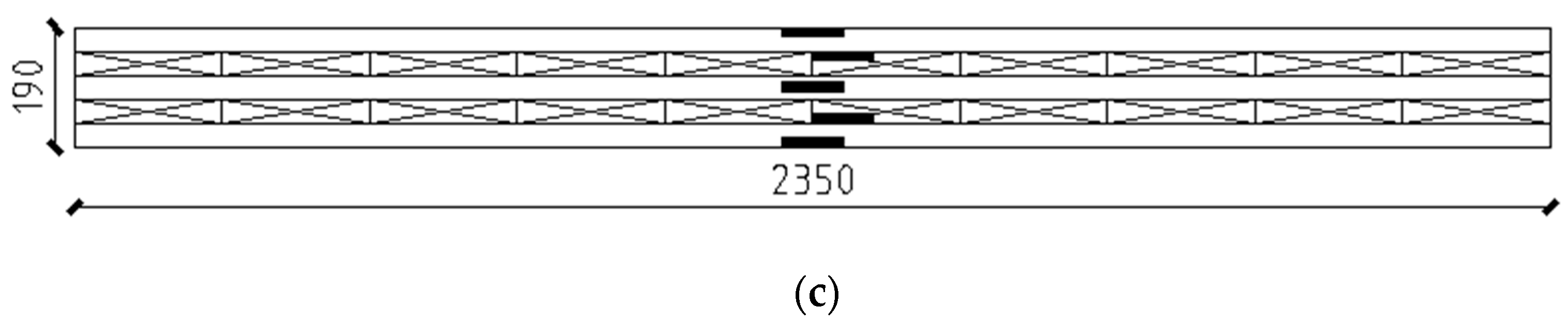
3.4.2. Calculation for 5-Layer CLT Panels
As shown in
Figure 15:
b = 705 mm,
h1 = h2= h3 = 38 mm,
= = 38 mm,
htot = 190 mm,
L = 2150 mm,
E = 11,200 MPa,
fb = 11.8 MPa,
GR = 50 MPa. In this case
E1 = E2 = E3,
Ai = bi hi, Ii =
,
= 1,
,
,
a1 =
,
a3 =
.
Since, A1 = A2 = A3 = A, a2 = 0, I1 = I2 = I3 = I
Hence, A = b × h = 705 × 38 = 26,790 mm2, a = = 76 mm
= 0.59
I = = 3.22 × 106 mm4
Hence, = = = 11,200 × 3.22 × 106 × = 2153 × 109 N·mm2.
Ieff = 192.234 × 106 mm4
Hence, = 0.9 × 11.8 × = 31.98 kN·m
Table 5 summarizes the ultimate bending moment of test specimens using the ultimate bearing capacity of each test specimen listed in
Table 4. For the three-layer NCLT panels, the measured ultimate bending moment of specimen 4 was 15.41 kN·m, slightly larger than the theoretical value
Mr = 15.11 kN·m. Due to the large size of the 5-layer NCLT panel, the probability of wood defects increased. In addition, cracks between plates caused by processing were also larger, and the NCLT panels were slightly warped. Therefore, the 5-layer NCLT panels test values were lower than the corresponding theoretical values, but the difference was within error range.
It can be observed that the difference between theoretical and measured ultimate bending moment values of the three-layer panel bending moment were large, with error ranging between 15.26% and 46.90%. This indicates that the bending moment calculated according to the mechanical connection theory Formula (7) was larger compared to corresponding experimental values, and thus needs to be corrected. It can be observed from the test results that the nail connection scheme improved the bending capacity of NCLT panels. Hence, a nail connection influence coefficient
α as a mathematical adjustment was introduced in the bearing capacity formula to correct for the bending moment value of the limit state, as shown in Equation (9). The adjustments are shown in
Table 6.
After this correction was implemented, the error was greatly reduced, and ratio between the average value of the measured bending moment and the corresponding theoretical bending moment was
= 1.006. Based on this, the theoretical calculation formula of the mechanical connection was modified as:
The European standard “Eurocode 1” [
22] stipulates that the standard value of the live load of building floors for domestic and residential activities is 2 kN/m
2. The ultimate bearing capacity of NCLT panels made with screws, which is the smallest, was converted to its plane load value of 26.1 kN/m
2, which is 13 times the value required by the standard. This underscores that the bearing capacity of the NCLT panels far exceeds the required value in specifications, demonstrating the great potential of NCLT panels in diverse structural engineering applications.


