Article

Properties of Sleeve Joints Made from Reduced Bamboo

1
Department of Wood-Based Materials and Design, National Chiayi University, 300 Syuefu Rd., Chiayi City 60004, Taiwan
2
Natural Resource Ecology and Management, Oklahoma State University, Stillwater, OK 74078-6013, USA
*
Author to whom correspondence should be addressed.
Appl. Sci. 2020, 10(17), 5985; https://doi.org/10.3390/app10175985
Submission received: 8 August 2020 / Revised: 21 August 2020 / Accepted: 26 August 2020 / Published: 29 August 2020
(This article belongs to the Section Materials Science and Engineering)

Abstract

:
Bamboo is a fast-growing species in the grass family, with excellent tensile and compressive strength characteristics, in the plant kingdom. The tapered hollow thin-walled cylindrical configuration of the bamboo species, namely, Gui bamboo (Phyllostachys makinoi Hayata) and Moso bamboo (Phyllostachys pubescens) culm, adversely influences its longitudinal shear and transversal tensile strength properties for effective use in engineered joints. The objective of this study is to use the thermo–hydro–mechanical (THM) process to reduce the irregular shape of bamboo ends without damaging the culms. Samples from the two abovementioned bamboo species were used for the experiments. Pullout loads and failure modes of the sleeve bamboo joints assembled by gluing were also evaluated. Eighty-nine out of 96 tested bamboo culms were successfully reduced by the THM treatment to uniform circular cross-sections under the maximum reduction ratio of 0.15. Sleeved-joint samples made from Gui bamboo with wood fittings had the highest pullout loads and strength values. Based on the findings in this work, it appears that THM-treated reduced bamboo ends, being a sustainable resource, could have the potential to be manufactured as steel-sleeve joints to be used for different engineering applications.

1. Introduction

Bamboo is one of the fast-growing species in the plant kingdom. Some bamboos can grow up to 90 cm in one day under the right climate conditions. Bamboo’s diameters, thickness, and internode length are macroscopically graded along the culm [1,2,3]. A typical bamboo has excellent strength properties, having high efficiency in terms of mechanical performance per unit weight, resulting in substantial resistance against wind load in nature [4,5]. Having a round structure, bamboo has been used in architectural applications since ancient times. However, bamboo has been utilized mostly in a simple form of structure due to its gradient anatomy, namely, diameter, thickness, and internode length. The round tapered hollow thin-walled cylindrical culm of bamboo makes it difficult to be used in the manufacture of reliable joints for structural applications. When hollow bamboo is loaded in bending, the shear load flow would be the highest within the culm walls. Concurrently, the circular culms would be ovalized by Brazier’s effect, which always results in kink foliation failure [6,7]. To avoid the bamboo parts being loaded in bending, the structure of round bamboo is designed as trusses so that load is applied either in tension or in compression without any bending [8]. Therefore, the bamboo unit would be loaded along the culm, having exceptionally high tensile and compressive strengths.
However, manufacturing engineering joints between two bamboo members still creates problems because of the low longitudinal shear strength and the transversal tensile strength of tapered hollow thin-walled cylindrical culm. Unlike wood pieces, which are mostly used in rectangular form, hollow round bamboos and metal pipes can only have contact with each other either in lines or at points. The connecting problem between metal pipes can be easily solved by screwing, bolting, and welding. Unfortunately, such practices cannot be applied in the case of bamboo to make reliable joints [9,10,11]. Hong et al. (2019) [12] reviewed traditional and modern connection joints. The modern connection joints include bolted joints, steel member joints, as illustrated in Figure 1a,b, and filler reinforced joints, as depicted in Figure 1c,d. According to their review, steel pipes can be either sleeved outside or inserted inside the bamboo culm and incorporated with filler to make integral joints, which provides high strength and ductility. However, with bamboo’s irregular shapes and diameters, it is almost impossible to join with standard pipes without either removing the bamboo materials or having a loose fit. In general, the exterior portion of bamboo is harder than the interior portion; therefore, removing the outer surface of bamboo culm would destroy the stronger portion of bamboo. The loose fit also needs filler to cover the gap between the pipe and bamboo, adding more uncertainties to the joint. The common practice of wood machining, such as turning or milling, could unify the bamboo end. However, the machining process is not only difficult to process due to the lack of reference surface resulting from nonuniform diameter but also destroys the integrity of the bamboo by eliminating the strongest part of the culm.
If the irregular form of bamboo ends, including nonuniform wall thickness, ovality, and unequal diameter, could be unified, then such standardized tube ends, matching the integral joint, could easily be manufactured since the uniform circular ends can provide an interface to make steel-sleeved bamboo joints. The steel sleeve could also be screwed, bolted, welded, and integrated with other types of connectors designed for steel pipes, such as blind bolts. If the application of tube-end-forming technologies to bamboo ends is feasible, then bamboo could have the potential to be used as a unique engineering material, having light weight and high strength [16]. However, lignocellulosic materials such as bamboo and wood species are brittle in air-dry conditions and ambient temperatures. Such a shortcoming of any lignocellulosic material can be enhanced by employing a thermo–hydro condition so that the viscoelasticity of the material can be improved [17,18]. The thermo–hydro–mechanical (THM) process has been used widely in the bending and modification of solid wood and wood products.
The softened bamboo ends can be modified under mechanical force using temperatures higher than the glass transition temperatures (Tg) of any lignocellulosic compound [17]. Therefore, the glass transition temperature of lignocellulosic components is a critical factor in the THM process. Huang et al. (2015) [19] reported that the glass transition temperature of solid Moso bamboo strips dropped from 217.3 to 113.0 °C for an oven-dried state or moisture-saturated condition. In a previous study, the modification of bamboo end diameters before they were flattened was studied by Sarula et al. (2012) [20]. Bamboo culm nosing was also investigated by Kitazawa et al. (2004) [16]. Both studies revealed that modification of bamboo culms is feasible under certain conditions. Additionally, once the bamboo ends have been reduced to a standard circular form, it is possible to mill the inner portion to a constant diameter and thickness. The concept of reducing and milling is shown in Figure 2. The outer and inner surfaces of the reduced and milled bamboo ends could provide interfaces for making an innovative joint, which could be a combination of the sleeve joint and the filler-reinforced joint. Such a combination, with high accuracy, strength, and ductility, could have excellent potential for commercial production for different applications.
Most of the properties of bamboo have been investigated in various studies; however, there is very limited information on the modification of bamboo ends using the thermo–hydro–mechanical process. Therefore, the objective of this study is to apply the thermo–hydro–mechanical process to reduce and modify bamboo ends for use in different joint applications. The pullout loads and failure modes of the steel-sleeved bamboo joints, which were assembled by gluing, with or without wood fittings, are also evaluated within the scope of this work.

2. Materials and Methods

2.1. Reducing Process of Bamboo Ends

Gui bamboo, also known as Makino bamboo (Phyllostachys makinoi Hayata), and Moso bamboo (Phyllostachys pubescens) samples were used to prepare the reduced bamboo ends. The average density and standard deviation values of Gui and Moso bamboo samples were 0.75 ± 0.07 and 0.89 ± 0.05, respectively. Both types of samples were kept in a conditioning chamber, having a temperature of 20 °C and relative humidity of 65%, until they reached equilibrium moisture contents of 8.0% and 8.1% for Gui and Moso bamboo specimens, respectively.
The outer diameters of Gui and Moso bamboo samples for reduction were determined by the inner diameters of preselected commercially available steel pipes, with 2 mm thickness. The values selected were 33.4 mm for Gui and 56 mm for Moso bamboo specimens.
According to past studies carried out by Sarula et al. (2012) [20] and Kitazawa et al. (2004) [16], the reduction ratio, which was defined as the ratio of diameter difference between the outer diameter and the target outer diameter to the initial outer diameter, was set from 0.00 to 0.15. Thus, the ranges of outer diameter for Gui and Moso samples were 33.4–41 and 56–65 mm, respectively. Bamboo culm specimens with 100 mm length, having a node and open ends, were used as reduced. Initially, all specimens were soaked in water for one week before they were preheated in boiling water for 30 min. Then, the specimens were located on a turning table running at a speed of 5 rpm. The open ends of the specimens were either heated by a butane torch or a hot air blower. The temperature of the inner surface of the bamboo culm was monitored by an infrared thermometer during the heating process. Once samples reached the glass transition temperature, specimens were put on top of a conical die to reduce their cross-sections by employing a piece of universal testing equipment, the Material Testing System (MTS). The specimens were pushed into the die at a crosshead speed of 1 mm/s for strokes of 45 and 60 mm for Gui and Moso bamboo specimens, respectively. Following the reducing process, the specimens, together with the die, were placed in an oven with a temperature of 40 °C for drying. A total of twenty-four samples were used for each combination of the equipment.

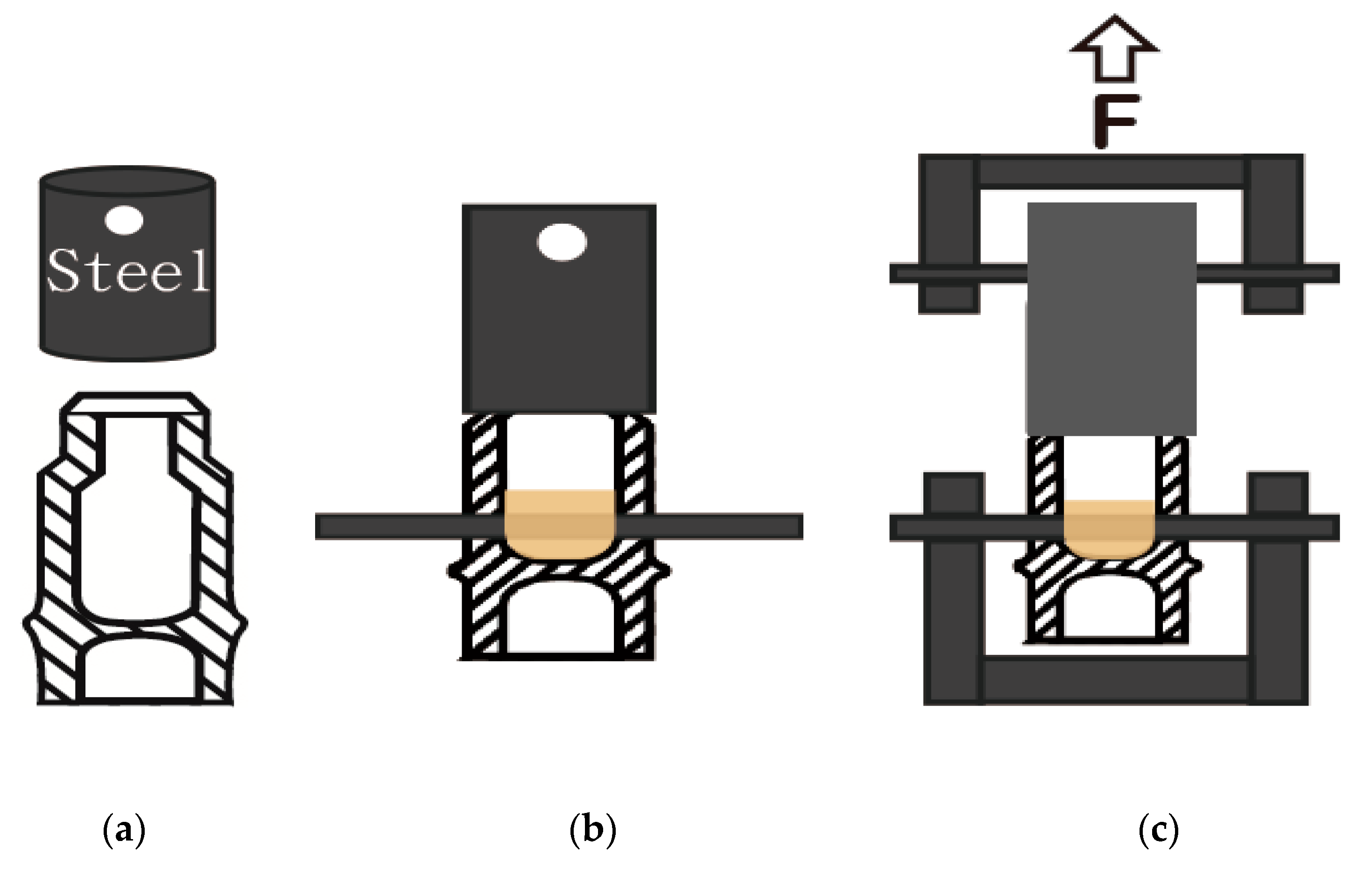
2.2. Testing of the Joints

Once the outer diameters of bamboo culms have been reduced to uniform configuration, the outer surfaces can provide a reference for milling the inner surfaces. The milling was processed by a pneumatic overarm router, having bits of 24 and 45 mm for Gui and Moso bamboos, respectively. After outside reducing and inside routing of the bamboo end samples, they become a standardized tube, with a constant diameter and thickness. The reduced bamboo ends and the steel sleeve were glued together with epoxy adhesive, with or without wood fittings, to form a steel joint, as shown in Figure 3a,b. Alaska cedar (Chamaecyparis nootkatensis), with a specific gravity of 0.48, was readily available in the wood mechanics laboratory and used for wood fittings of the joints. The main reason for using wood fitting was to fill the cavity so that the structure can be in a solid state, with a good foundation for screws.
Two sheet metal screws, having a diameter of 3 mm and a thread length of 16 mm, were used at two opposite points of the sleeve to transmit the pullout load on wood fittings. The embedded length in wood fittings was about 8 mm. In order to avoid failure occurring in the node end, the nodal diaphragm was reinforced with epoxy to distribute the overall bearing load, as illustrated in Figure 3b. The pullout load of the steel joints was tested using a crosshead speed of 0.025 mm/s by employing a Material Testing System (MTS) universal testing machine, as shown in Figure 3c. A total of twelve samples were tested for each combination.

3. Results and Discussion

3.1. Reducing Process

Fire heating and hot air heating were used to raise the temperatures of the preheated specimens to reach viscoelastic state. Figure 4 shows the number of successes and failures of reducing bamboo samples. Failures of the samples were determined by visual observation and the load-displacement curve by defining a sudden drop as a failure. It can be observed that there were 5 failures out of 48 for hot air heating and 2 out of 48 for fire heating. The two-sample proportion statistical test showed that no significant difference existed between the two heating methods with regards to the failure ratios. It was also observed that the fire heating by butane torch could raise the temperature to reach the glass transition temperature faster than that of the hot air blower. Besides the heating method, other factors such as the reduction ratio, maximum outer diameter, wall thickness, and moisture content value could also be considered as the parameters influencing the overall success of the reduction. A typical successfully reduced bamboo end is illustrated in Figure 5a. If the maximum diameters are larger than the opening diameter of the conical reducing die, the bamboo culm cannot be pushed thoroughly into the die; this would cause partial crushing, as shown in Figure 5b. When the reduction ratio is too large or the final temperature is not high enough, the bamboo culm will have a circumferential crush (Figure 5c) caused by hoop stresses [21,22].

3.2. Reducing Force of the Samples

Figure 6a,b is a simplified schematic of the reducing process and typical load–displacement curves of the reducing process for Gui and Moso bamboo culms, respectively. The driving load increases as the culm gets in contact with the conical die until the culm reaches the cylindrical portion of the die. The peak load is defined as the reducing force in this study. After the bamboo culm enters the cylindrical portion of the conical die, the driving load drops due to the champher and then increased gradually due to the interference of contact stress that is normal to the culm’s surface. The drop of the driving load values is simply caused by the champer of bamboo culms. The movement of the specimen in the cylindrical portion follows the Coulomb law of friction. The driving load (F) is the product of the frictional coefficient (μ) and the normal force (N) (F = μN). The normal load (N) is equal to the multiplication of the normal contact stress (p) and the contact area (A) (N = pA). The contact area is the product of the inner circumferencial length (C) and displacement (d) (A = Cd). The normal contact stress (p) and frictional coefficient (μ) may be constant for a certain reduction ratio. However, the contact area (A) increases with the moving displacement (d). Therefore, the driving load increases with the displacement (F = μpCd), as shown in Figure 6b. The final maximum load depends on the displacement of stroke and is always higher than the reducing force.
The reducing forces for various reduction ratios are illustrated in Figure 7 for Gui and Moso bamboo samples with different deduction ratios. As a high reduction ratio represents higher contact stress, the reducing force should increase with increasing values of reduction ratio,as shown in Figure 7. It was also determined that the reducing forces of bamboos heated with fire are always lower than those heated with hot air because the fire heating raises the temperature more efficiently. This trend is more obvious in the case of Gui bamboo samples.

3.3. Reduced Outer Diameter and Ovality of the Samples

One of the objectives of this study is to reduce irregular bamboo ends to give them a uniform and round diameter without any damage to the bamboo culms. Table 1 summarizes the basic statistics of the outer diameters of Gui and Moso bamboo specimens before and after the reduction. A paired t-test was performed to compare the mean diameters of the samples accordingly. The reduced outer diameters are significantly smaller than the original outer diameters of both Gui and Moso bamboo samples.
It appears that the outer diameter of the bamboo samples could be reduced by the thermo–hydro–mechanical process under the specified maximum reduction of 0.15. The standard deviations of the original and the reduced outer diameters were compared by a two-variance F-test. The standard deviations of the reduced diameters of the specimens were significantly smaller than those of the original outer diameters, indicating that the reduced bamboo ends had a more uniform diameter.
Bamboo culms are usually not perfectly round in shape. To simplify their out-of-roundness, it was assumed that the cross-section of bamboo was oval. The ovality or the out-of-roundness can be defined as the difference between the long axis and the short axis. When ovality equals to zero, the cross-section is assumed to be circular. The histograms of ovality for Gui and Moso bamboos are shown in Figure 8. The average ovality and the standard deviation values of Moso bamboo samples, before and after the reduction, were 2.18 and 0.89 mm, respectively. Corresponding values of Gui bamboo samples were found as 1.71 and 0.38 mm. The statistical analysis proved that the average ovality and the standard deviation values of the samples after reduction were significantly smaller than those of the original specimens, indicating that the cross-sections of reduced bamboos were a uniform circular shape. According to Eurocode 3 (CEN 2007), the out-of-roundness of pipes is defined by the difference between the long and short axes divided by the nominal diameter. The ovality limits are 0.014, 0.02, and 0.03 for Class Av(Excellent), Class Bv(High), and Class Cv(Normal), respectively. If the ovality values in Figure 8 are divided by the associated nominal diameters, the values of out-of-roundness for Gui and Moso bamboos would be 0.011 and 0.016, which can be considered in Class A and Class B, respectively. This reveals that the ovalities of the reduced bamboo ends have met the industrial standard.

3.4. Sleeve Joint Test of the Samples

The joint without fitting consists of reduced bamboo, sleeve, and adhesive, while the joint with fitting has reduced bamboo, adhesive, sleeve, wood fitting, and screws. Joint failure could take place either in the components, namely, bamboo, sleeve, fitting, and screw or in the glue lines between the bamboo–sleeve or bamboo–wood fitting. It is clear that a steel sleeve cannot fail among the components. Therefore, the failure of the joint without wood fittings took place in the bamboo and the adhesive. As the exodermis of bamboo is very hard to bond due to the wax and SiO2, the glue layer between the bamboo and the steel sleeve is expected to be the first failure for joints without wood fittings [23]. Additionally, the relationship between strength properties and the density of bamboo is quite different from that of wood species. Overall, the strength characteristics of bamboo are directly related to their surface properties rather than density. The glue line between bamboo and a wood fitting did not fail because the glue layer was not loaded in the pullout test. Screws in the joint with wood fittings might fail or yield due to transverse shear load. The overall failure of the steel joint occurred in bamboo, glue line, and screw. Such findings were confirmed by the results of the pullout test of the steel joint. As screw failure always occurred right after adhesive failure, such failure was considered an adhesive failure [23]. Failure modes of the samples were simply classified as adhesive failure and bamboo failure, as shown in Figure 9.
The number of failure modes for various joint types is depicted in Figure 10. As can be seen from this figure, forty adhesive failures and eight bamboo failures were determined for steel-sleeved joints. Bamboo failures took place only for the wood fitting joints and always occurred in the diaphragm where the pullout load was applied. Pullout test failures in bamboo parts referred to the glue layer, and, together, the screws were stronger than bamboo. The use of screws fixed in wood fittings significantly increased the joint strength. This implies that a steel-sleeved joint with wood fittings is stronger than bamboo by the use of more screws.
The displacement of the crosshead of the testing machine was recorded as the deformation of the sleeve joint that took place during the test. Figure 11 illustrates the typical load–displacement curves for steel-sleeved Gui and Moso bamboo joints, with and without wood fittings, representing the load and deformation of the tested joints. As shown in Figure 11, the joints without wood fittings (blue square symbols) have abrupt drops of load after reaching the maximum pullout load, indicating that the joint failure is a brittle one. Drop of load represents the separation between bamboo and its sleeve. However, joints with wood fittings (red circular symbols) had ductile failure behavior. Initially, the magnitude of load did not drop to zero because even though the failure occurred between bamboo and sleeve, the screws still resisted a certain amount of pullout load until the screws either yielded or failed. In the next step, the deformation of the joint with wood fittings was much larger than the joint without wood fittings. Zhang et al. (2018) [23] studied steel-reinforced bamboo square columns jointed by epoxy and screws. The steel–bamboo interface also showed similar load–displacement curves of brittle and ductile behavior, without and with screws, respectively.

3.5. Pullout Load and Strength of the Samples

The maximum pullout load and strength for various types of joints, with standard error bars, are depicted in Figure 12. As can be seen in Figure 12, Gui bamboo sleeved joints had higher pullout loads and strength values than those of Moso bamboo joints. Joint strength was calculated by dividing the pullout load by bonding area. Having wood fittings could significantly increase the pullout load and strength of the joints. The lower pullout load of Moso bamboo joints might have resulted from poor bonding, as previously explained.
In a past study, the bonding strength of the interface between steel and Moso bamboo plywood, with epoxy of test samples, was determined as 0.78, 0.80, and 0.80 MPa Wen (2014). For the other three samples with epoxy and self-tapping screws, it was 1.07, 1.10, and 1.11 MPa.
Comparing those bonding strength values with the ones in Figure 12, the mean values of the strength of steel-sleeved Gui bamboo joints, with and without wood fittings, were 2.30 and 3.07 MPa, respectively, which are much higher than the bond strengths listed in Wen’s study (2014) [24]. Steel-sleeved Moso bamboo joints, however, had only comparable mean values of 0.76 and 1.04 MPa. Fabiani’s test (2014) [25] showed that Moso bamboo joints with wood fittings using 24 screws with a diameter of 6 mm under tension could withstand 57,600 N. Figure 12 shows that a steel-sleeved Moso bamboo joint with wood fittings, reinforced by 2 screws with a diameter of 3 mm, could have mean pullout load of 8462 N. From Figure 11 and Figure 12, it can be observed that wood fittings substantially improve the joint strength and ductility by accurately filling the cavity of bamboo culms. The yield model theory used in the Wood Handbook (Forest Products Laboratory 2010) [26] to predict the lateral resistance of a screw joint might be employed to estimate the steel-sleeved bamboo joint, treating the steel sleeve as a side member and bamboo/wood as the main member. As such, the pullout load could be treated as lateral resistance. The joint strength could, therefore, be directly related to the dowel-bearing stresses of bamboo and steel and nail numbers and sizes.

4. Conclusions

This study applied the thermo–hydro–mechanical process to reduce irregular bamboo ends to make uniform round diameters without damaging the bamboo culms. Gui and Moso bamboo end samples were soaked, heated, and reduced. Eighty-nine out of 96 tested culms were successfully reduced under the maximum reduction ratio of 0.15. It appears that fire heating raised the temperature faster than hot air heating and has a lower reducing force. The reducing force increases with an increase in the reduction ratio. The reduced bamboo ends have uniform circular cross-sections with less variation in both outer diameter and ovality. Additionally, reduced bamboo ends could provide a standard interface to be connected with commercially available steel tubes to form reliably engineered bamboo joints. Steel-sleeved bamboo joints were assembled by gluing the reduced bamboo ends and steel sleeves, with/without wood fittings, with epoxy adhesive. Gui bamboo sleeve joints had higher pullout loads and strength values than those of Moso bamboo joints. The failure modes for steel-sleeved bamboo joints included adhesive and bamboo failures. Steel-sleeved joints with wood fittings and screws had higher strengths and ductility than the joints without fittings because the wood fitting provides material for screws to be anchored. The steel-sleeved bamboo joint with fittings could provide a promising engineering joint for round bamboo structures. Bamboo, as a sustainable nonwood species, with excellent strength properties and low cost, would have great potential to be used in such joints, which are applicable for different uses. The processes of reducing bamboo ends and the production of steel-sleeved joints on a commercial scale would benefit the use of more environmentally friendly resources. In further studies, different properties, including surface quality and behavior during the service life of the joints studied in this work, would be desirable to investigate in order to have a better understanding of such units.

Author Contributions

Conceptualization, Y.W.; Data Curation, Y.W.; Investigation Resources, Y.W. and S.H.; Writing–review and editing, Y.W. and S.H. Both authors have read and agreed to the published version of the manuscript.

Funding

This study received no external funding.

Conflicts of Interest

The authors declare no conflict of interest.

References

  1. Amada, S.; Munekata, T.; Nagase, Y.; Ichikawa, Y.; Kirigai, A.; Zhifei, Y. The mechanical structures of bamboos in viewpoint of functionally gradient and composite materials. J. Compos. Mater. 1996, 30, 800–819. [Google Scholar] [CrossRef]
  2. Akinlabi, E.T.; Anane-Fenin, K.; Akwada, D.R. Bamboo: The Multipurpose Plant; Springer International Publishing AG: New York, NY, USA, 2017. [Google Scholar]
  3. Mannan, S.; Knox, J.P.; Basu, S. Correlations between axial stiffness and microstructure of a species of bamboo. R. Soc. Open Sci. 2017, 4, 160412. [Google Scholar] [CrossRef] [PubMed] [Green Version]
  4. Sutnaun, S.; Srisuwan, S.; Jindasai, P.; Cherdchim, B.; Mmatan, N.; Kyokong, B. Macroscopic and microscopic gradient structures of bamboo culms. Walailak J. Sci. Technol. 2005, 2, 81–97. [Google Scholar]
  5. Wegst, U.G.K.; Bai, H.; Saiz, E.; Tomsia, A.P.; Ritchie, R.O. Bioinspired structural materials. Nat. Mater. 2014, 14, 23–36. [Google Scholar] [CrossRef] [PubMed]
  6. Huang, Y.S.; Hsu, F.L.; Lee, C.M.; Juang, J.Y. Failure mechanism of hollow tree trunks due to cross-sectional flattening. R. Soc. Open Sci. 2017, 4, 160972. [Google Scholar] [CrossRef] [PubMed] [Green Version]
  7. Wegst, U.G.K.; Ashby, M.F. The structural efficiency of orthotropic stalks. stems and tubes. J. Mater. Sci. 2007, 42, 9005–9014. [Google Scholar] [CrossRef]
  8. Hibbeler, R.C. Engineering Mechanics: Statics and Dynamics, 12th ed.; Prentice Hall: New Jersey, NJ, USA, 2010. [Google Scholar]
  9. Janssen, J.J.A. Building with Bamboo—A Handbook; Practical Action Publishing Ltd.: Rugby Warwickshire, UK, 1995. [Google Scholar]
  10. Kaminski, S.; Lawrence, A.; Trujillo, D. Structural use of bamboo, Part 1: Introduction to bamboo. Struct. Eng. 2016, 94, 40–43. [Google Scholar]
  11. Adhikari, R.C.; Wood, D.H.; Sudak, L. Low-cost bamboo lattice towers for small wind turbines. Energy Sustain. Dev. 2015, 28, 21–28. [Google Scholar] [CrossRef]
  12. Hong, C.; Li, H.; Lorenzo, R.; Wu, G.; Corbi, I.; Corbi, O.; Xiong, Z.; Yang, D.; Zhang, H. Review on connections for original bamboo structures. J. Renew. Mater. 2019, 7, 713–730. [Google Scholar] [CrossRef] [Green Version]
  13. Disén, K.; Clouston, P.L. Building with bamboo: A review of culm connection technology. J. Green Build. 2013, 8, 83–93. [Google Scholar] [CrossRef]
  14. Fabiani, M. Tensile Test of a New Connector for Bamboo Structures. 2013. Available online: https://www.youtube.com/watch?v=5KG04gJ3mU4 (accessed on 3 August 2020).
  15. Arce, O.E. Fundamentals of the Design of Bamboo Structures. Ph.D. Dissertation, Eindhoven University of Technology, Eindhoven, The Netherlands, 1993. [Google Scholar]
  16. Kitazawa, K.; Takahama, M.; Ogawa, H. Possibility of nosing of common Japanese bamboo. J. Mater. Sci. 2004, 39, 1473–1476. [Google Scholar] [CrossRef]
  17. Navi, P.; Sandberg, D. Thermo-Hydro Mechanical Processing of Wood; EPFL-Rolex Learning Center: Lausanne, Switzerland, 2012. [Google Scholar]
  18. Fang, C.H.; Jiang, Z.H.; Sun, Z.J.; Liu, H.R.; Zhang, X.B.; Zhang, R.; Fei, B.H. An overview on bamboo culm flattening. Constr. Build. Mater. 2018, 171, 65–74. [Google Scholar] [CrossRef]
  19. Huang, M.; Zhang, W.; Zhang, X.; Yu, W.; Li, W.; Liu, X.; Dai, C.; Wang, S. Factors for Phyllostachys edulis timber glass transition temperatures. J. Zhejiang A F Univ. 2015, 32, 897–902. [Google Scholar]
  20. Sarula, S.N.; Yoshitani, K.; Tanahashi, M. Development of novel flattening method for bamboo cane by the high-pressure steam processing. Mokuzai Gakkaishi. 2012, 58, 193–200. [Google Scholar] [CrossRef] [Green Version]
  21. Storozhev, M.V.; Popov, E.A. Theory of Plastic Metal Working; Mashinostroenie: Moscow, Russia, 1977. [Google Scholar]
  22. CEN (European Committee for Standardization). Eurocode 3-Design of Steel Structures-Part 1–6: Strength and Stability of Shell Structures; EN 1993-1-6: 2007 (E); CEN-CENELEC Management: Brussels, Belgium, 2007. [Google Scholar]
  23. Zhang, J.; Li, Y.; Liu, R.; Xu, D.; Bian, X. Examining bonding stress and slippage at steel-bamboo interface. Compos. Struct. 2018, 194, 584–597. [Google Scholar] [CrossRef]
  24. Wen, Y. Research on Bonding Properties of Bamboo-Steel Interface under Cyclic Loading. Master’s Thesis, Ningbo University, Ningbo City, China, 2014. [Google Scholar]
  25. Fabiani, M. Bamboo Structures: Italian Culms as Likely Resource for Green Buildings. Ph.D. Dissertation, Marche Polytechnic University, Ancona, Italy, 2014. [Google Scholar]
  26. Forest Products Laboratory. Wood Handbook: Wood as an Engineering Material; USDA General Technical Report FPL-GTR-190; USDA Forest Service, Forest Products Laboratory: Madison, WI, USA, 2010. [Google Scholar]
Figure 1. (a) Joint with steel pipe capped at bamboo ends (Adhikari et al., 2015) [11]. (b) Joint with steel pipe inserted at bamboo ends (designed by Shoei Yoh, cited in Disén and Clouston 2013) [13]. (c) Joint with wood fitting and screws (Fabiani 2014) [14]. (d) Joint with round wood block inserted in bamboo culm (Arce 1993) [15].
Applsci 10 05985 g001
Figure 2. (a) Tube reducing. (b) Cross-section of original culms. (c) Outside reducing. (d) Inside milling. (e) Uniform circular end with constant thickness and diameter.
Applsci 10 05985 g002
Figure 3. (a) Reduced bamboo and steel sleeve. (b) Steel joint. (c) Pullout test set-up.
Applsci 10 05985 g003
Figure 4. The number of successes and failures of various bamboo and heating methods.
Applsci 10 05985 g004
Figure 5. (a) Reduced bamboo end (Moso bamboo). (b) Partial crushing. (c) Circumferential failure.
Applsci 10 05985 g005
Figure 6. (a) Reducing process. (b) Typical load–displacement curves.
Applsci 10 05985 g006
Figure 7. The reducing forces for various reduction ratios for the samples.
Applsci 10 05985 g007
Figure 8. The histograms of ovality before and after the reduction of the samples.
Applsci 10 05985 g008
Figure 9. Bamboo failure (a) and adhesive failure (b) of sleeved Gui bamboo joints.
Applsci 10 05985 g009
Figure 10. Failure modes for various joints.
Applsci 10 05985 g010
Figure 11. Load–displacement curves of steel-sleeved Gui and Moso bamboo joints, with and without wood fittings.
Applsci 10 05985 g011
Figure 12. The pullout loads and strengths of various joints (bars are one standard error from the mean).
Applsci 10 05985 g012
Table 1. Comparison of means and variances of outer diameters before and after reducing.
Moso BambooGui Bamboo
OriginalReducedOriginalReduced
Minimum (mm)55.7054.9534.6532.64
Maximum (mm)65.2558.6238.9033.88
Mean (mm)60.6657.0236.7133.2
Paired t-test for equal meanst = 12.59t = 20.71
p (single tail)p < 0.001p < 0.001
Standard Deviation (mm)2.5420.8481.3190.262
f-test for equal variances f = 9.00f = 25.21
p (single tail)p < 0.001p < 0.001

