Article

Effect of Competent Caliche Layers on Measuring the Capacity of Axially Loaded Drilled Shafts Using the Osterberg Test

by
Rouzbeh Afsharhasani
,
Moses Karakouzian
and
Visar Farhangi
*
Department of Civil and Environmental Engineering and Construction, University of Nevada, Las Vegas, NV 89154, USA
*
Author to whom correspondence should be addressed.
Appl. Sci. 2020, 10(18), 6169; https://doi.org/10.3390/app10186169
Submission received: 15 July 2020 / Revised: 10 August 2020 / Accepted: 1 September 2020 / Published: 4 September 2020
(This article belongs to the Section Civil Engineering)

Abstract

:
This study investigates the effect of the location of an O-cell hydraulic jack along the length of a drilled shaft in a full-scale Osterberg test performed in soils containing layers of caliche. The location of the hydraulic jack with respect to caliche layers influences the measurements obtained from the Osterberg test and the subsequent interpretation of drilled shaft capacity. In this study, drilled shaft capacities were derived utilizing data from 30 Osterberg full-scale field load tests in soils containing caliche layers. The hydraulic jack was placed at the midpoint of the drilled shaft length. Additionally, the Osterberg test data was used to calibrate a numerical model by Plaxis finite element software for drilled shaft analysis. Using the calibrated model, several scenarios of hydraulic jack location were simulated. The scenarios included hydraulic jack locations at several distances above and below a caliche layer. The results of the simulations indicate that in cases where the O-cell was installed far from the caliche layer, the Osterberg tests results showed lower pile resistance capacity compared to the top-down test. However, in cases where the O-cell was installed close to the caliche layers, the Osterberg tests results showed comparable pile resistance capacity compared to the top-down tests. This study recommends installing the hydraulic jack as close as possible to the caliche layers for more reliable interpretation of the Osterberg field tests which leads to a cost-effective design approach by reducing the required shaft length.

1. Introduction

The general design procedure for drilled shaft foundations in soils is primarily based on the ultimate values of drilled shaft skin friction and end bearing capacity [1]. The basic load transfer mechanisms were identified through early research on drilled shafts [2,3]. This method is appropriate for soils in conventional geological settings in the absence of highly cemented caliche deposits. Caliche is the hard lithification of fine-grained sediments, along with sand and gravel layers, which form through secondary cementation by calcium and magnesium carbonate [4,5]. The federal highway code of design [6] considers caliche a sedimentary rock in the design procedure of deep foundations. Therefore, the design parameters of drilled shafts in interaction with rocks are recommended for the interaction of drilled shafts and caliche deposits. The shaft/caliche bond is considerably strong [7] and can bear high-range loading conditions. Caliche layers are usually underlain by weak soils. The bending of the caliche deposits as part of the caliche-pile monolithic system is due to the additional flexural strength of these deposits in the soil profile [8].
The bidirectional Osterberg load test results in soils containing caliche indicate that the ultimate capacity of skin friction and shaft/caliche interaction is not achieved during the full-scale tests [9]. This issue can be anticipated due to limited slippage between the drilled shaft and the surrounding soil layers that prevent the drilled shaft from reaching its ultimate capacity [10]. Such a limitation affects the reliability of the measured results using Osterberg bidirectional tests, which are only reliable should the ultimate side resistance capacity of the pile be measured.
The presence of competent caliche layers in soil is beneficial for reducing pile settlements. For example, vertically installed underpinned mini-piles (micropiles) were vertically installed and bonded to strong existing caliche layers to control the vertical displacement of the Mandalay Bay hotel/casino in Las Vegas, NV [11]. In this project, a jet-grouting method was used to enhance the bearing capacity [12] of the soil using micropiles to control the differential settlement of the building [13,14]. Choi et al. [15] conducted an analytical and experimental study on the capacity of the micropiles implemented in heterogeneous soil profiles containing rock layers. They asserted that the maximum load-carrying response of the micropile elements occurs when these types of piles are installed vertically in interaction with competent rock layers. Furthermore, increasing the stiffness of the piles using fiber reinforced polymers enhances the axial and bending capacity of piles in interacting with rock and highly cemented layers, and controls the displacement issues of the piles [16,17,18,19,20,21,22,23,24,25,26,27,28]. Haberfield et al. [18] proposed that the satisfactory response of piles depends on the stiffness of the rock and caliche compared to the strength properties of these deposits.
In the past, a few research studies have investigated the interpretation of the Osterberg test in the presence of strong, cemented caliche layers in soil. For instance, Asem et al. [29] suggested that the current practice neglects the presence of highly cemented material in soil profiles close to the ground surface level. At a significant distance from the O-cell apparatus in the test procedure, the upward movement begins by mobilizing the soil layers with lower stiffness values, whereas a top-down test mobilizes the stiffer material in the early stages of loading. Therefore, the tests report two different load–movement responses near the pile head.
Berisavljevic et al. [30] recommended additional interpretation measures based on the different procedures of the bidirectional Osterberg test and conventional top-down test. The most significant difference is that the compressional loading at the head of a shaft in the top-down test causes compression in the concrete, causing outward radial strain (Poisson’s effect), and affects the load transfer distribution within the shaft’s depth. Bidirectional loading by the O-cell sacrificial jack also produces compression in the concrete pile; however, the load transfer distribution changes from the maximum in the location of the O-cell to almost zero at the head of the pile. Different patterns of load transfer distribution result in various distributions of side resistance within the pile’s depth, depending on subsurface conditions, which in respect affect the measured total side resistance of a rock socket at the shaft head, using an Osterberg test [31,32].
Seo et al. [33] evaluated the available data that might allow direct comparisons between the Osterberg and conventional top-down loading tests on drilled shafts. Based on this evaluation, the differences in rock socket response between Osterberg and top-load tests are due to the modulus of the rock mass at very high slenderness ratios and interface friction angles. The study suggested that the equivalent top-load–settlement curve derived from an Osterberg load test under predicts side resistance for higher displacements.
Conventional design methods for measuring the bearing capacity of drilled shafts are mainly developed for soil profiles in the absence of strong cemented layers, such as competent caliche. In previous research studies, the effect of side shear distribution on assessing the resistance capacity of the drilled shaft was investigated in homogenous soil [34,35]. However, to the best of the authors’ knowledge, few studies investigated the distribution of the side shear resistance of piles in soil containing competent cemented or strong rock layers. [36,37]. The presence of such strong layers, affect the side shear capacity of a drilled shaft due to the interaction of these competent layers with the concrete pile. Moreover, full-scale tests, such as a conventional top-down test and an Osterberg cell test, are designed to measure the capacity of the drilled shaft in the absence of such cemented layers in the soil. Therefore, the presence of caliche competent layers in the soil profile enforces limitations on the traditional methods of drilled shaft test and design. These limitations can lead to unnecessarily conservative design, by underestimating the capacity of the drilled shafts.
This study addresses this shortcoming in the design process of drilled shafts, and investigates the effect of competent caliche layers underlain by weak geomaterial on evaluating the response of axially loaded drilled shafts following full-scale Osterberg test results. The current load test approach is investigated for soil containing caliche. The soil profile in which the drilled shafts were installed is predominantly clay/clayey sand with highly cemented caliche layers. The load tests were performed in accordance with ASTM D-1143 “Quick Load Test Procedures” [38]. The effect of pile’s elastic shortening on constructing equivalent top-down load–displacement curves based on the Osterberg test’s measurement was reported by Xu et al. [39]. In the present study, the elastic shortening is considered for a more accurate analysis of drilled shaft responses.

2. Laboratory Data and Field Measurements

In the presented research, 30 full-scale Osterberg test results for drilled shafts in soil containing caliche are acquired, along with their associated laboratory and field test data.

2.1. Laboratory Data

Consolidation tests were conducted following ASTM D3550 [40] specifications using ring samples on the undisturbed samples. Atterberg limits were performed according to the ASTM D4318 [41] standard. The reported plasticity index is shown in Figure 1. In addition, the direct shear test, in accordance with ASTM D3088 [42] specifications, indicated that the average friction angle ranged between 20 and 35 degrees, and the cohesion varied within the 200 to 300 and 400 to 500 psf for the clayey sand and lean clay/fat clay soils, respectively. Las Vegas soil stratigraphy consists of seven main soil types including clayey Sand (SC); silty sand (SM); lean clay with traces of caliche or gravel (CL); fat clay (CH); sand and gravel (GP, GM, GC); and cemented layers, such as cemented sand and gravel. The characteristics of each mentioned soil type can vary within the depth in the site location.
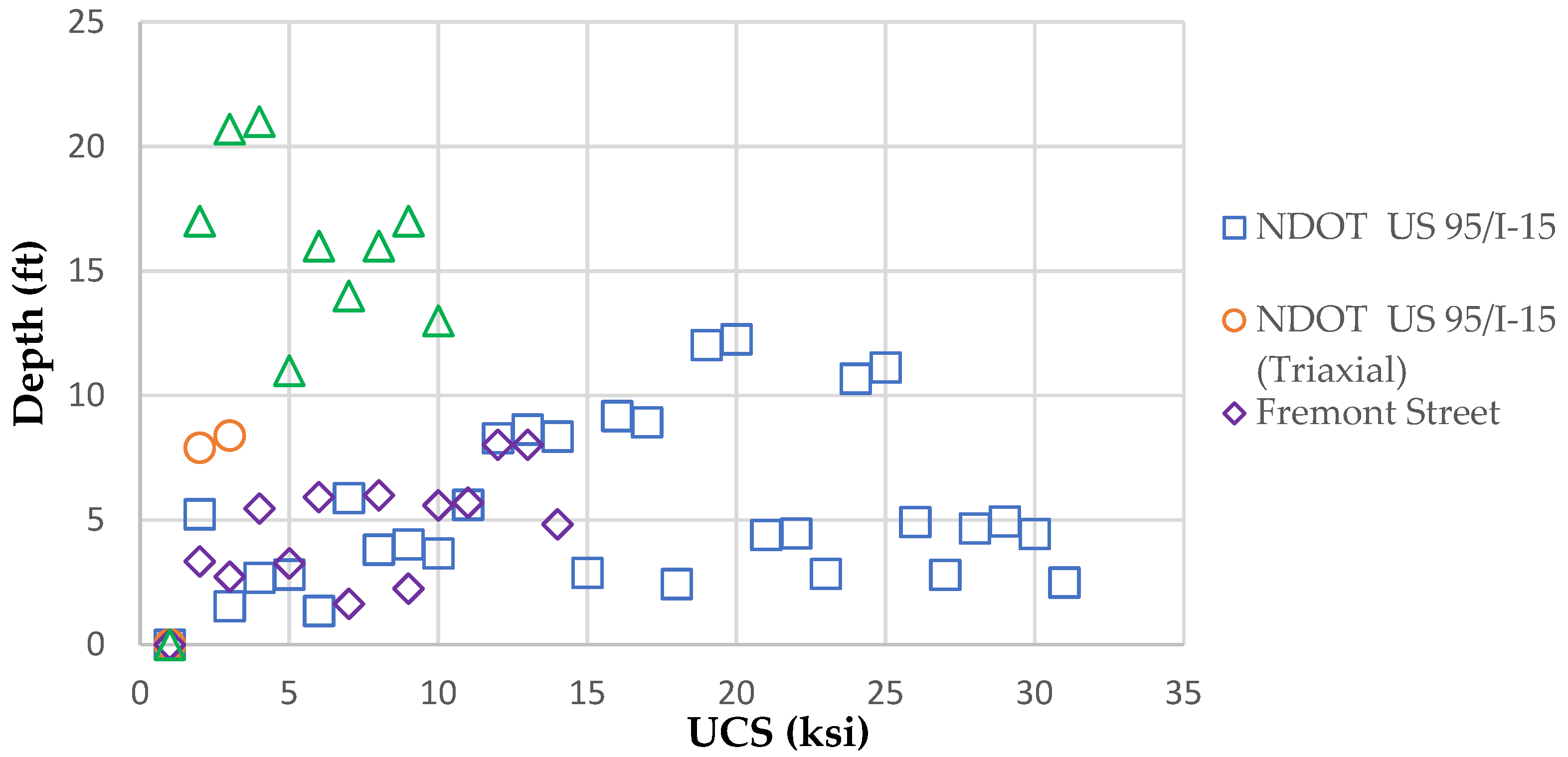
Consolidated undrained (CU) tests, along with unconfined compressive strength (UCS) tests, were performed on caliche core samples at the project sites to determine the strength properties of these deposits. Considering practical issues, the Shelby tubes in the soil containing stiff gravel layers and highly cemented deposits were not used. In this regard, the samples were acquired using a California modified ring sampler (split spoon sampler). The average unconfined compressive strength of the caliche deposits following the results of the UCS tests was reported as 8ksi. Following the UCS results, the existing caliche layers were categorized in hard to very hard range (competent) deposits. Figure 2 presents the measured UCS values based on the depths of the acquired core samples for the caliche following the four available geotechnical reports in this study. The saturated triaxial tests were conducted by applying 14 psi confining pressure with a constant strain rate of 0.03 in the evaluation procedure of the caliche properties.

2.2. Field Data

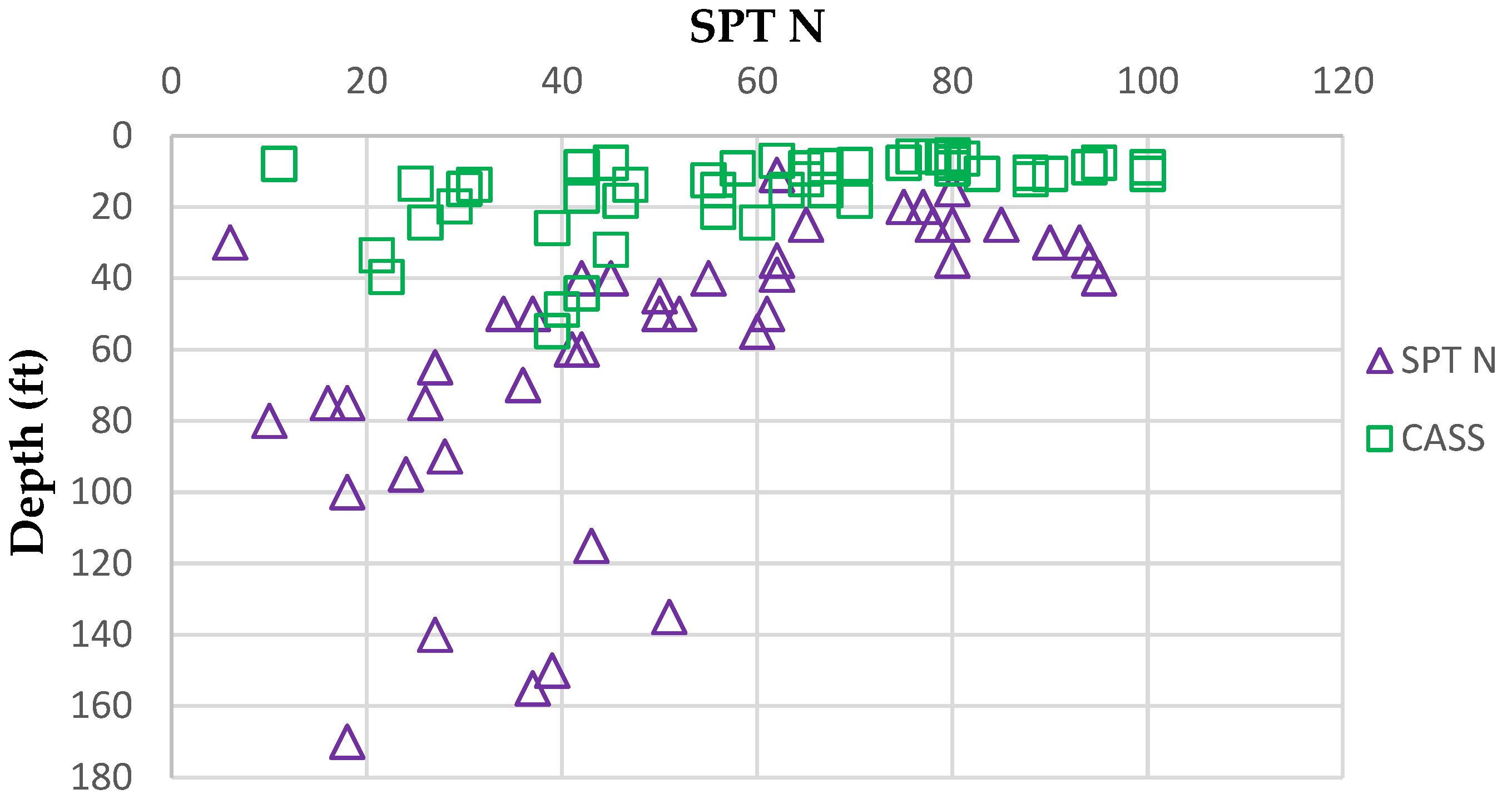
Samples were acquired by modified California split spoon (CASS) and standard split spoon (SPT) samplers. Figure 3 shows the measurements of these penetration tests based on the reported borings. Although the CASS and SPT reported scattered measurements, the results show the heterogeneous soil in the project is stiffer up to 40 feet of depth from the ground surface level.

2.3. Measured Pile Data

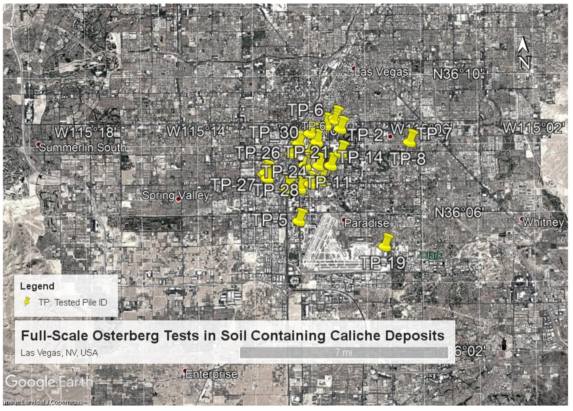
The reported full-scale tests in this research consist of 30 bidirectional tests in the Southern Nevada Valley, as is shown in Figure 4. Load test data for drilled shafts in caliche were acquired from different locations in Las Vegas to address the variations in the geologic formations of this area. During the tests, constant screenings were performed to measure the displacement of the installed drilled shafts using the strain gauges along the piles’ length. The most competent caliche layers at the case study sites were located at 10 to 20 feet depths below the ground level in Southern Nevada. Their thicknesses varied between 5 to 15 feet. The conducted tests based on the pile ID along with the depth and thickness values of the caliche layers in the soil profile are presented in Table 1. Geometries of the drilled shaft and caliche layers, along with the measured bidirectional loads, according to those of the 30 bidirectional Osterberg tests, are also summarized in Table 1. The location of the installed O-cell apparatus within the pile length is reported in this table. The pile diameters’ ranges are within 36 to 48 inches and the installation length varies between 62 and 128 feet. In addition, the maximum O-cell load was applied to achieve the ample amount of the pile’s tip movement related to the ultimate capacity of the piles. In the design procedure, the required pile tip displacement is selected be equal to 2% of the pile diameter for both upward and downward load application to measure the pile ultimate capacity based on the allowed displacement. The maximum load applications by the O-cell hydraulic jack during the tests were reported in ranges from 1959 to 7358 kips.
The validity of the collected data was analyzed based on the measured full-scale tests in various scenarios, regarding the location of the caliche layers with respect to the O-cell hydraulic jack in the Osterberg test procedure. To further evaluate the results of the Osterberg test in soil containing caliche deposits, a finite element analysis [43,44,45,46] was conducted using the commercial PLAXIS 2D V8.6 program. The difference between the upward and downward mobilization of the test shafts in Las Vegas, NV was identified following two case study analyses. Moreover, a procedure was recommended to enhance the design accuracy of the drilled shafts in Las Vegas, NV.

2.4. Interpretation of the Measured Full-Scale Bidirectional Osterberg Load Tests

Caliche is a very hard material with considerable load-bearing capacity. It is important to test the caliche layers properly for an appropriate estimation of shaft capacity. The reported load test data were categorized into four categories based on the location of O-cell, with respect to the existing competent caliche deposits, to study the outcome of the Osterberg tests in both upward and downward load applications. The location of the O-cell, based on the defined categories, is presented in Figure 5. The O-cell apparatus was installed above, between, and under the existing caliche layers, in proximity to or far from the competent caliche. Osterberg tests were performed in a controlled condition to enhance the reliability of the results. The outcomes of the Osterberg cell test in these four categories are analyzed and presented in the following sections.

2.4.1. O-Cell Located above and Close to the Caliche

Competent caliche deposits showed great strength during the load tests; therefore, drilled shafts required a significant amount of load to be mobilized in soil profiles. The most competent caliche layers in the Southern Nevada Valley existed near the surface level in the soil profile. If the O-cell was installed above the caliche, the soil above could not produce enough side resistance to fully mobilize the caliche layer. Therefore, the result would be limited movement of the caliche in the downward mobilization of the lower part of the shaft, and failure in the upper section of the drilled shaft. The applied load from the O-cell was sufficient to measure the ultimate capacity of the upper part of the test shaft; however, it was not adequate to mobilize the lower part. Therefore, the Osterberg test could not measure the ultimate capacity of the drilled shaft, which is based on the total capacity of the pile subject to both upward and downward loading. The outcome can lead to an unreasonable long length design of the drilled shaft.

2.4.2. O-Cell Installed between the Caliche Layers

If the O-cell was installed between the concentrated caliche layers, both the upper and lower part of the shaft could develop enough resistance to measure the capacity of both caliche layers. The load–displacement test results were expected to show limited to the full mobilization of the upper and lower portions of the shaft in interaction with caliche.

2.4.3. O-Cell Located under and Close to the Caliche

One of the most common load test layouts is when the O-cell is installed underneath the caliche layer, and the lower shaft sections extend to a lower depth. The extension into lower depths provided enough resistance in the lower section of the shaft to mobilize the caliche in the upper section. Since caliche is stronger than typical soil layers, mobilizing the shaft capacity requires a larger amount of load compared to a general soil profile. In order to generate that load and prevent failure at early loading stages in the opposite direction (lower section of the shaft), the shaft lower section is extended into lower depths to provide the system with the counter resistance to balance out the resistance from the caliche. The Osterberg test results are more reliable using this approach, considering that the resistance in the lower section of the shaft stays in balance with the resistance of the upper section. Therefore, more reliable load–displacement curves for upward and downward movement of the shaft can be reported by the Osterberg test.

2.4.4. O-Cell Installed under and Far from the Caliche

When the O-cell was installed far from caliche competent caliche layers, the lower section of the shaft could not provide enough resistance to resist the reaction of the upper section. Indeed, this case was the reverse of the first scenario where the soil failed before mobilizing the caliche layers; except this time, the lower part of the shaft failed before the upper section of the shaft. The test layout resulted in the failure of the lower section and limited mobilization of the upper section.
The first and fourth scenarios could result in unnecessarily conservative design approaches since the reported measurements of the load–displacement response of the pile by the Osterberg test was not able to provide ultimate values in either of the shaft sections, below or above the O-cell. The second scenario, where the O-cell was installed between two competent caliche layers, provided a more justifiable layout to measure the capacity of both caliche layers in one test. The results from the third scenario show that this test layout is also acceptable for measuring the capacity of the upper and lower sections of the drilled shaft. The third and fourth scenarios are commonly used in Osterberg test layouts in Southern Nevada, and are investigated in this research to study the effect of O-cell location on the interpretation of test results.

3. Plaxis Finite Element Analysis

Finite element (FEM) analysis was conducted following the results of two case study projects. The prime objectives were to study the behavior of drilled shafts under bidirectional loads, compare results with the field results, and investigate force/stress distributions along the shaft’s length in soil containing caliche layers. Results of the test were verified following Osterberg’s main assumptions [47,48]. He assumed the shaft resistance–movement curve for upward movement of the pile is the same as the downward side-movement component of a conventional top-down test.
The results of the FEM analyses were used to determine the parameters involved in the approximate design model. Fifteen node triangle axisymmetric elements were used in the simulation of the concrete shaft, soil layers, and caliche. The element stiffness matrix was evaluated by numerical integration, using a total of three Gauss stress points [49,50,51,52]. The installed O-cell hydraulic jack in the shaft was simulated as a one-foot empty void. The load by the O-cell was applied at the bottom of the upper section of the shaft for upward loading as well as the top of the lower section of the shaft for downward loading. The width of the mesh was assumed to be 150 feet from the center of the shaft and the depth of the mesh was twice the length of the shaft which is 200 feet.
A constitutive model was used to create a soil model in accordance with the field measurements and following Hooke’s law of linear elasticity theory to describe soil behavior in the collapse state [53]. Coulomb’s law of perfect plasticity was used for simplification purposes. The concrete material in the shaft was assumed to be an isotropic, homogeneous and elastic solid with the assigned Poisson’s ratio of υ = 0.15, which is a typical value for drilled shafts [54]. The interface element between the shaft concrete and soil layers were modeled to be part of the soil layer with 0.1 feet of length. Interface elements were selected for each individual soil and caliche deposit. An elastic-plastic model, using the Mohr–Coulomb (MC) criterion [55], was used to simulate the effect of the interfaces in the modeling of the pile in interaction with the soil layers. The Mohr–Coulomb model was also selected to represent these soil layers. The finite element model was calibrated based on the different values of shear strength parameters of the soil and caliche layers to agree well with the experimental Osterberg load test results.

3.1. Effect of O-Cell Location on the Interpretation of Test

A simple soil stratigraphy was selected with the sandy clay soil type to perform the analysis. The soil profile included a 10-feet layer of caliche, which at first was located at the depth of 50 feet. The O-cell was installed under the caliche layer. The test was performed using the material properties shown in Table 2. The loads simulated the measured values according to the Osterberg test reports. The location of the caliche layer with respect to the installed O-cell was analyzed for the caliche layers located at different distances from the O-cell. The resulting load–displacement values were converted to an equivalent load–displacement curve in the top-down test. The properties of the caliche and soil layers during the analysis were remained constant.
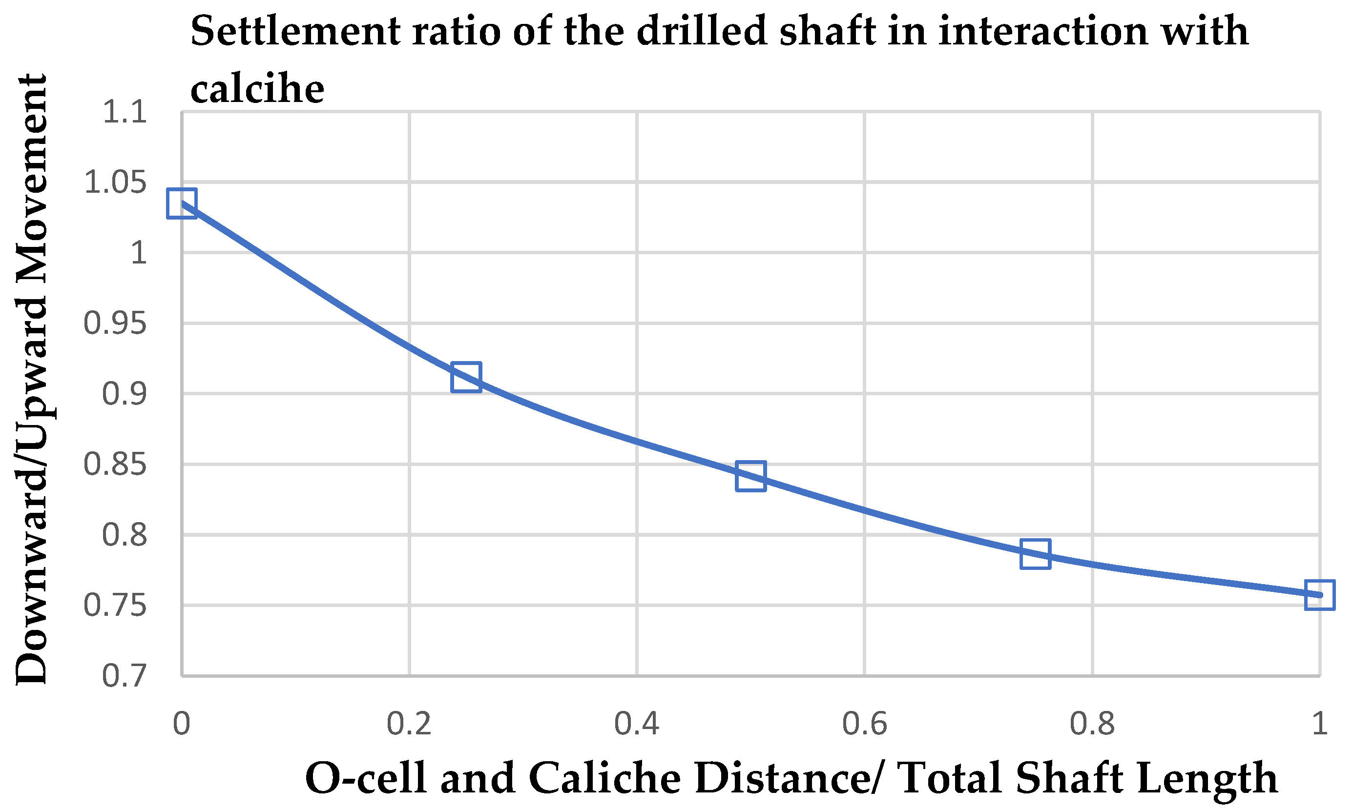
The results of the finite element analysis show that the changes in the location of O-cell along the drilled shaft length with respect to the caliche layer affects the interpretation of the test results. The ratio of the downward to upward movement of the pile subjected to the bidirectional test was calculated. As shown in Figure 6, increasing the distance between the location of the O-cell apparatus and the caliche layer reduces the downward to the upward settlement ratio of the drilled shaft. The caliche layer is not mobilized to the maximum of its capacity if the O-cell is installed far from the caliche. This can be reasoned due to the dissipation of the applied load by the O-cell through the soil layers, as a small portion of the load from high depths reaches the caliche layer, which exists close to the ground surface level. During the upward loading by the O-cell, the mobilization of the caliche layer is more considerable, compared to the downward load application and produces higher resistance values for the specified pile settlements. Based on the analysis, if the O-cell is located to the nearest possible existing competent caliche deposit, the outcomes of top-down and bidirectional Osterberg tests are comparable.

3.2. Case Study Analyses

In this section, the ultimate upward and downward shaft resistances in the soil containing competent caliche layers are investigated using the finite element simulation. The initial stresses, including the self-weight of the caliche and soil layers, were applied prior to the application of the structural loads to differentiate both upward and downward loadings in the simulation. The calibration analysis was conducted according to the reported soil properties. Different O-cell locations with respect to the depth of the competent caliche layer were considered in the analysis.
In the presented case studies, the finite element simulation of upward and downward load components of the Osterberg test was compared with the constructed top-down load test based on the measured load–settlement values of the pile. In addition, parametric analyses using t–z curves were conducted to further analyze the pile response in interaction with the competent caliche deposits.
The following steps and assumptions were followed during the finite element analysis of the two case studies. An axisymmetric model was adopted considering the boundary conditions of the pile load test. The Mohr–Coulomb failure criterion was used for the soil layers and caliche. Interface elements were defined along the shaft length to simulate the soil–pile interaction, and extended 0.1 feet beyond the shaft’s perimeter. Based on available borehole data and laboratory tests, the soil profile consisted of sandy clay, clayey sand, stiff clay, cemented sand and gravel, or caliche. Due to the quick load application by the Osterberg test, an undrained condition was assigned to the soil layers. The drained strength parameters used in the simulation were determined based on the reported bore log and adjusted following the laboratory results. The soil layers were considered as normally consolidated, and the elastic compression pile was incorporated in the analysis. The modulus of elasticity of concrete (Ec) material in the drilled shaft was determined based on the Ec = 57000√fc’ equation, where fc’ is the concrete unconfined compressive strength and is reported 585,000 ksf. A drilled shaft stiffness (EA) of 7,360,000 kips was used in the analysis. The soil properties were adjusted to reach the best agreement between the back analysis results and measured data and presented along with the concrete characteristics of the drilled shaft, as summarized in Table 2 and Table 3.

3.2.1. Case Study I: Caliche at the Far Location from the O-Cell

Case Study I is based on the TP-19 Osterberg test, in which the caliche layers existed very close to the ground surface and far from the O-cell. The material properties used in the analysis are presented in Table 2. Two competent caliche deposits were located at depths of 18 and 30 feet with thicknesses of four and six feet, respectively. The O-cell was located below the lower caliche layer at depths of 50 and 80 feet, and the drilled shaft was subjected to the total axial load of 3316 kips. The strain gauges were installed along the shaft length to record the pile displacement. A very fine mesh was used in the procedure of the finite element simulation. Similar to the field load application with the Osterberg test, the load was applied in the simulated model in 15 consecutive loading stages up to 3316 kips. The water table was defined at an 85-foot level, following the boring data to simulate the phreatic conditions to include an undrained state.
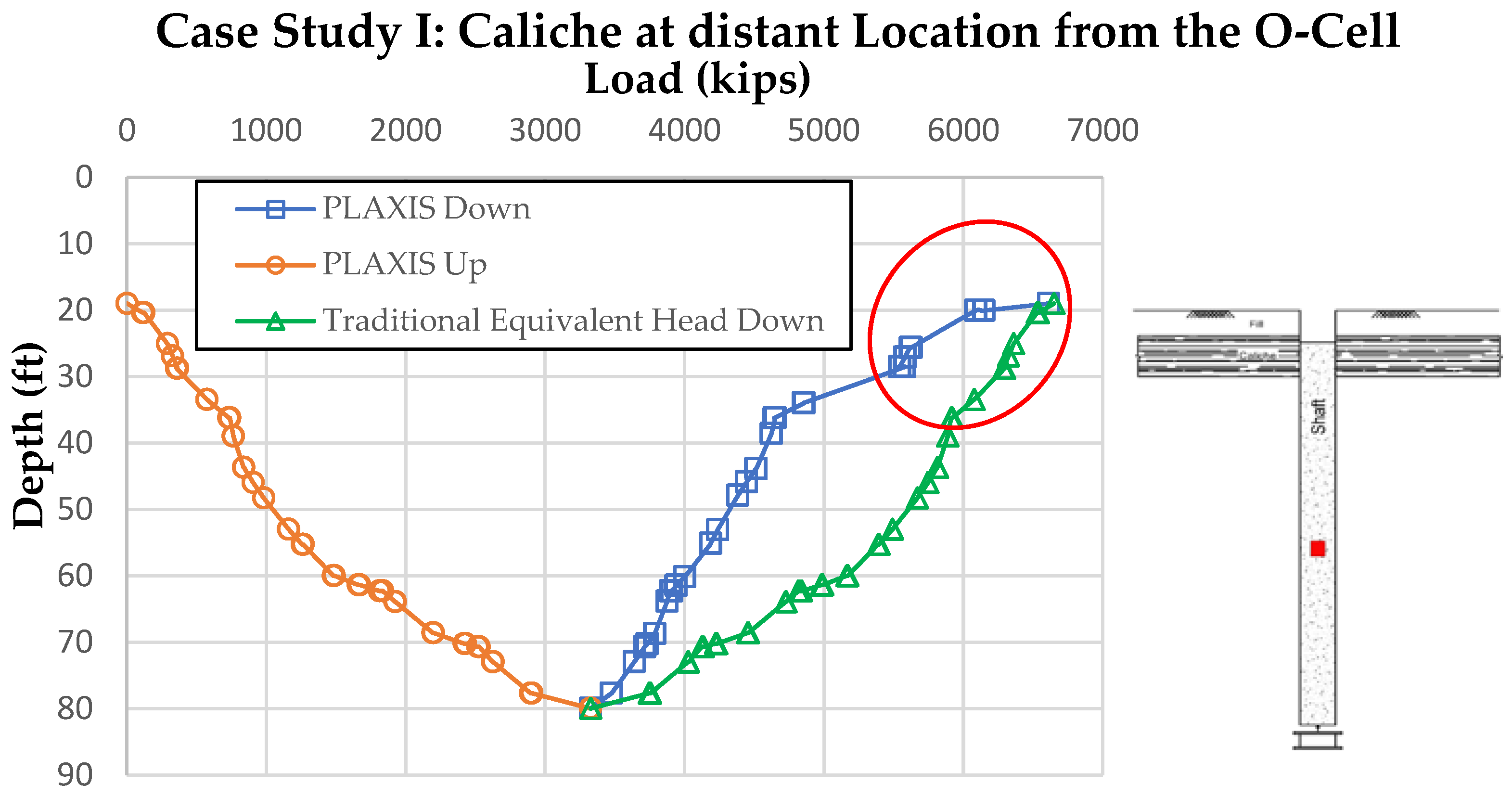
The results of both loading scenarios, the Osterberg bidirectional test, and a conventional top-down test were analyzed using the load transfer, t–z curves, and load–settlement diagrams. As shown in Figure 7, the soil layers between caliche and O-cell carry more loads in the upward loading compared to top-down loading conditions. More load has been carried by caliche layers in the top-down loading scenario.
The load transfer curve shows that the upward axial load of 6400 kips was decreased to 4500 kips at depths of 19 to 36 feet, while the load transfer curves of the Osterberg tests show a slight decrease of 500 kips within the same length. The finite element analysis showed that the amount of dissipated load in the caliche from the conventional loading scenario was more than three times than the reported results using the top-down test. Since the caliche layer was located at a distant location from the O-cell, the caliche could not be fully mobilized by the O-cell during the Osterberg test. Therefore, the measured load-bearing capacity of caliche could estimate just a portion of the pile’s full capacity. Unlike the Osterberg test, a comparable load from the top could mobilize the caliche more, and consequently, more unit shear stress was developed.
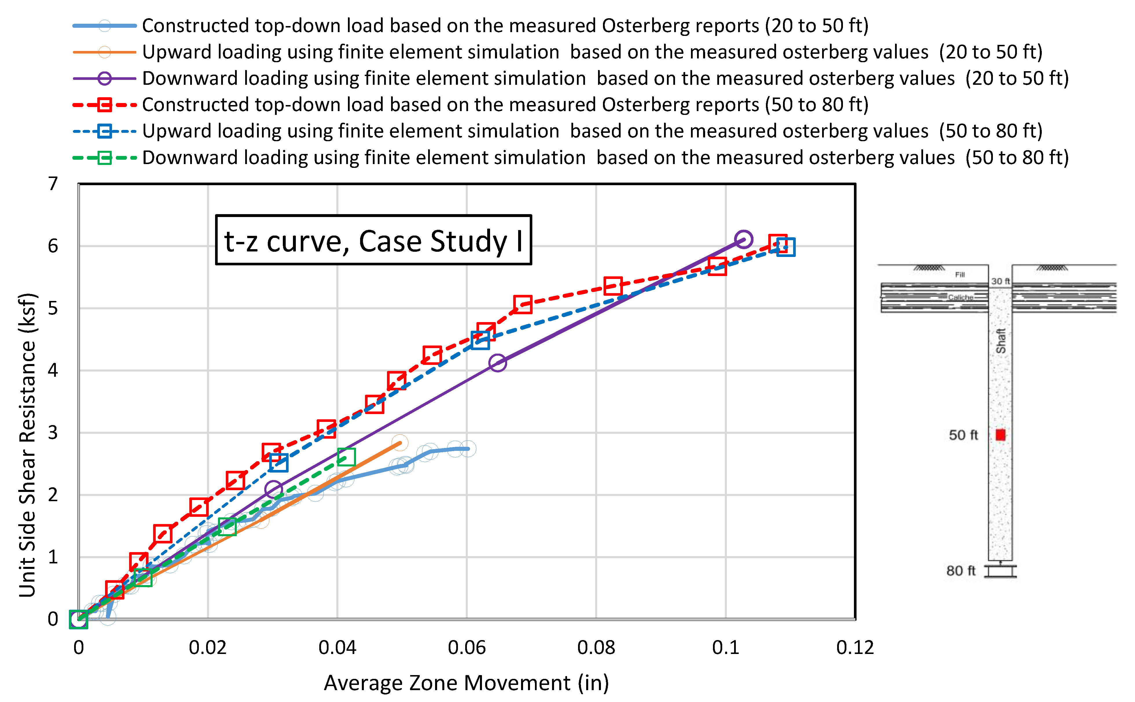
The nonlinear stress–strain responses of the drilled shafts in the soil containing caliche layers were also investigated using t–z stiffness curves. In this regard, t–z curves were used to analyze the results of the calibrated upward and downward loading components of the Osterberg test as finite element models, and compare them to the theoretical top-down loading, which was constructed based on the measured values reported by the field Osterberg test. Figure 8 illustrates the t–z curves following the displacements recorded by the installed strain gauges between 20 and 50 feet, along with the gauges installed within 50 and 80 feet. The O-cell was installed at the depth of 80 feet.
The calibrated finite element model showed comparable unit shaft shear resistance to constructed top-down test in depths between 50 and 80 feet, and reached its ultimate unit resistance capacity of about 6 ksf during the constructed top-down load test and upward finite element simulation. The downward load application within the 50 and 80-foot depths showed an elastic pile response and the ultimate resistance capacity was 2.5 ksf. At farther distances from the installed O-cell (e.g., depths within 20 and 50 feet from the ground surface level), the ultimate unit shear resistance of the top-down and upward finite element simulation was reported as 3 ksf, which is half of the ultimate side resistance value, at 50–80 feet for the same load application. The t–z analysis results confirm the assumption that pile capacity is not accurately measured by the Osterberg test if the O-cell is installed at a distant location from the competent caliche deposit.
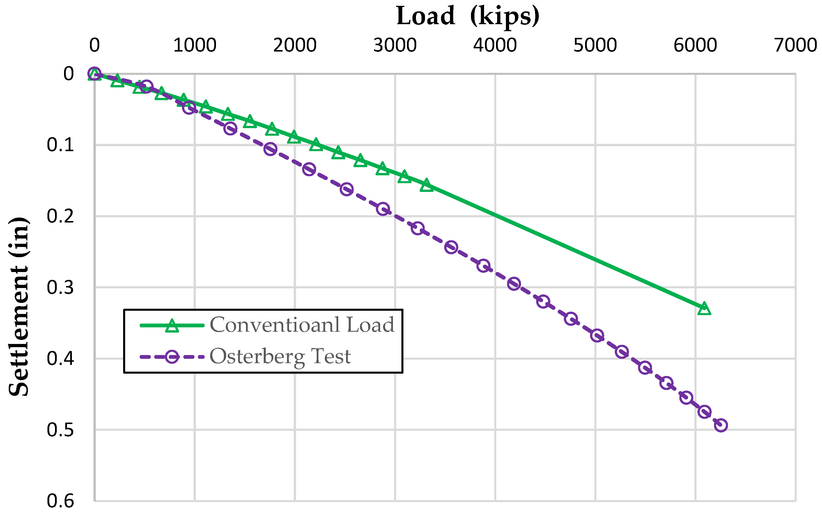
According to the outcomes of the parametric analysis of Case Study I, Figure 9 illustrates a constructed top-down curve according to the proposed back analysis method in the presented case studies, along with the constructed top-down curve based on Osterberg’s assumptions. A comparison of the curves shows that the load-bearing capacity of the drilled shaft attributed to a specific displacement is less than Osterberg’s recommended method for an O-cell installed far from the competent caliche deposit. In the proposed research, the effect of pile elastic compression is considered, which is disregarded in the original assumption by Osterberg.

3.2.2. Case Study II: Caliche Close to O-Cell

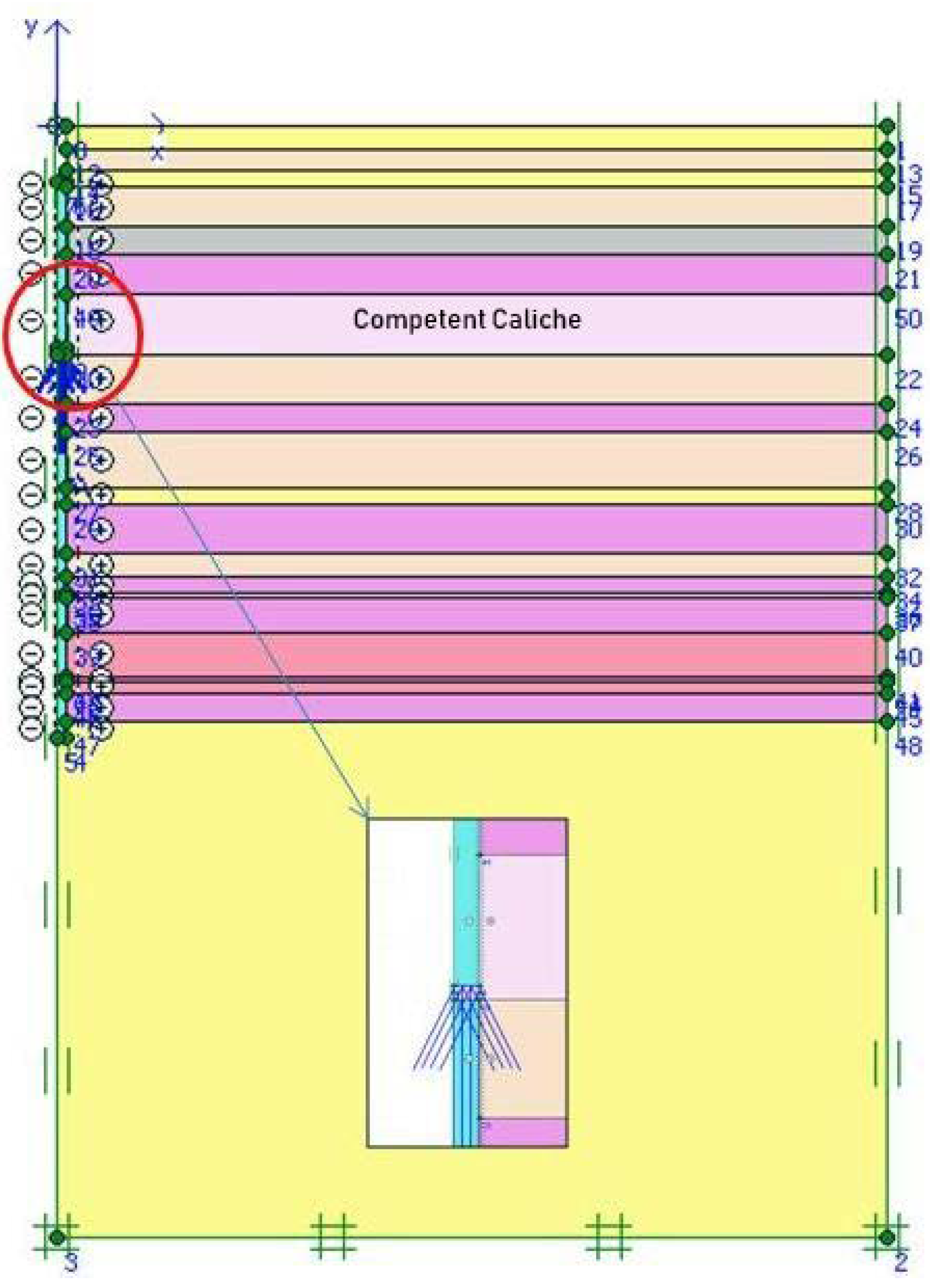
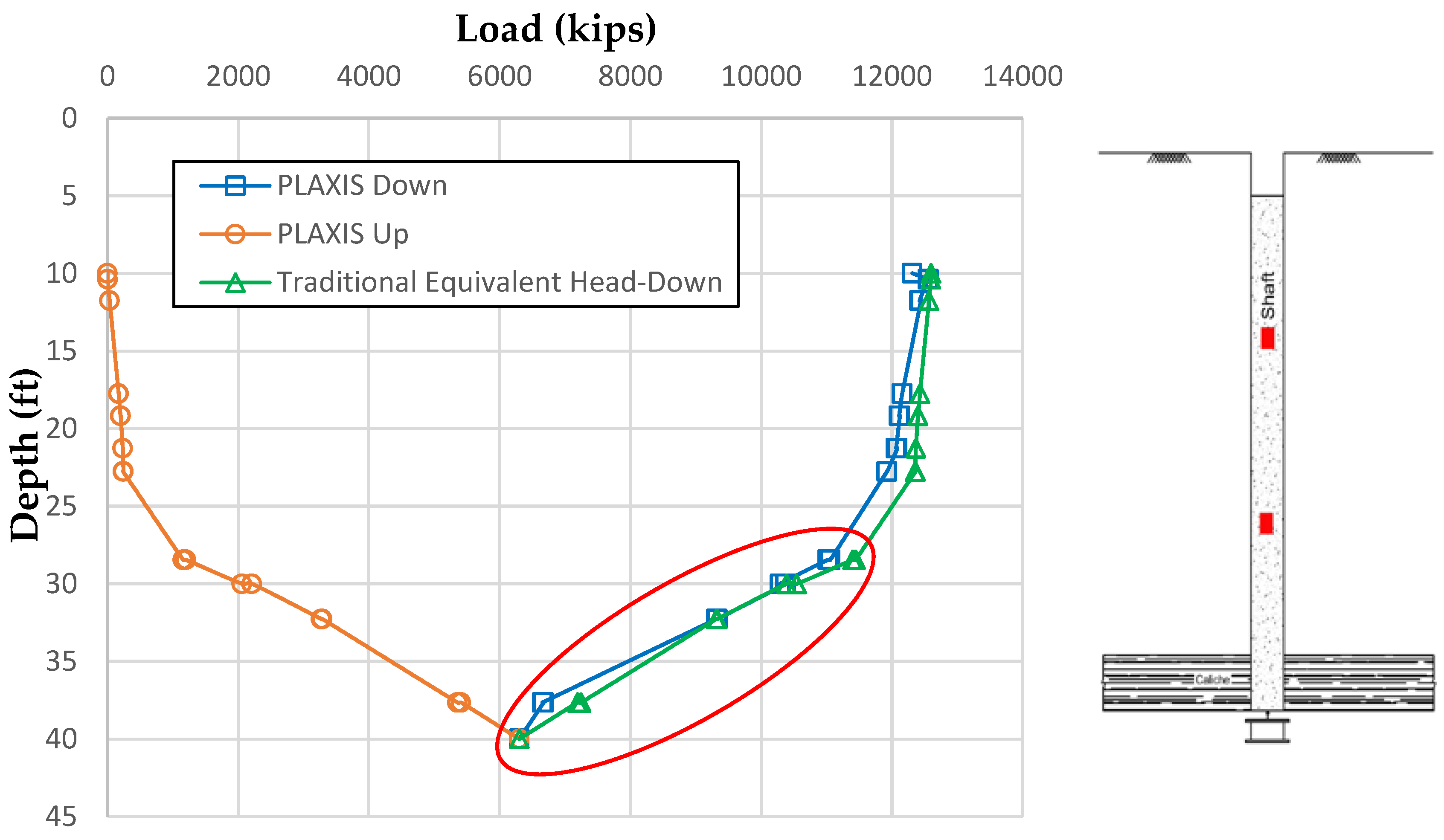
Case Study II presents the analysis of the TP-17 Osterberg test as the material properties shown in Table 3. The O-cell hydraulic jack was installed close to the competent caliche layers. The finite element method was used to simulate the Osterberg test. The O-cell was installed at 40 feet from the ground surface level. Caliche layers were located at depths of 23 and 50 feet, with thicknesses of 18 and five feet, respectively. The bidirectional load application by the O-cell was measured to a peak value of 6128kips during the test procedure. Similar methods and assumptions to Case Study I were followed in the simulation of the axially loaded drilled shaft, as well as soil materials. The Osterberg test was performed in 10 loading stages to avoid the effect of dynamic impact during the load application. The water table was considered in the analysis at 22 feet, close to the depth of the existing caliche layer. The simulated finite element model is presented in Figure 10.
The load transfer curves for simulation of Osterberg’s upward and downward load components, along with the top-down loadings are shown in Figure 11. The caliche and soil layers was subjected to relatively similar loads during the traditional top-down and the bidirectional Osterberg tests.
The slight differences between these downward loads in the simulation, and the top-down test were due to the existence of a few geomaterial layers located close to the ground surface that were mobilized further in the top-down test compared to the Osterberg load application. Caliche was the most dominant load-carrying mechanism in this test layout.
Additionally, the results were similar to the rock socketed drilled shaft. Based on this analysis, the capacity of the pile subjected to the upward or downward loading in the presence of the caliche is comparable. The major difference between the two analyzed case studies was due to further mobilization of the caliche deposit during the Osterberg test when the O-cell was located close to this deposit. Accordingly, during the downward loading application, the load transfer mechanism agreed well with the top-down measurements. Unlike Case Study I, caliche did not show any excess capacity due to further mobilization.
Similar to the previous case study, the t–z curves from the calibrated finite element model are compared to theoretical top-down loading. Figure 12 shows t–z curves according to the displacements in three depth ranges, 10–20 feet, 20–30 feet and 30–40 feet. The load–settlement pattern in the simulation and top-down test were comparable. The slight changes in the pattern can be justified due to the mobilization of geomaterial close to the ground level during the test applications. However, such a mobilization does not contribute to enhancing the ultimate load-bearing capacity. In the analysis, the results of the calibrated finite element model agree well with the outcome of the Osterberg test. The results show that when the O-cell is placed close to the caliche layer, the difference between upward and downward loading is the least.
To further analyze the behavior of the axially loaded drilled shafts based on the top-down and bidirectional tests, the load–settlement responses were investigated. The upward and downward load–settlement curves of the drilled shaft in the Osterberg cell was reconstructed with an equivalent load–settlement curve, and was compared to curves reported from the conventional loading.
Figure 13 illustrates the load–settlement results for the traditional method based on the Osterberg assumption [47]. The load–settlement response of the pile based on the constructed Osterberg test by back analysis, and constructed conventional tests based on the measured Osterberg values are quite comparable. The similarity of the results further shows the reliability of the Osterberg test as an alternative to the top-down test, if the O-cell is installed close to a competent caliche layer.

4. Results and Discussion

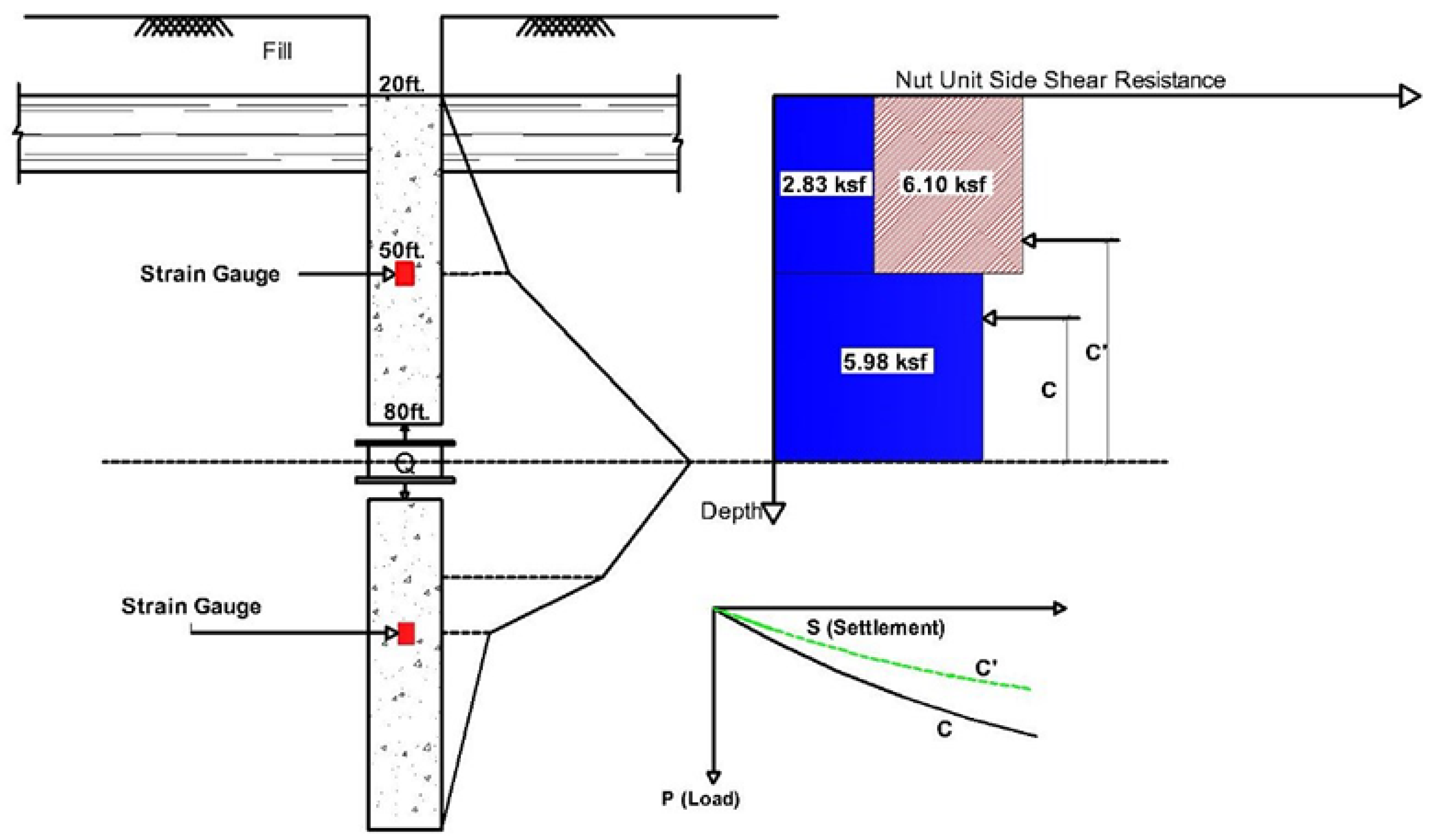
The effect of the O-cell location with respect to competent caliche layers was investigated. In Case Study I, the O-cell was installed far from the caliche layer, whereas, in the second scenario (Case Study II), the O-cell was installed close to a strong caliche layer. It can be perceived from the results that the caliche is not fully mobilized when the load cell is located very far from it. The load is dissipated through the soil layers before transferring to the caliche layer, and only a slight portion of the load was reached to mobilize the caliche. Hence, the resistance developed from the caliche was the reaction of this deposit to a small portion of the total applied load. The mobilization did not fully represent the caliche’s capability. The caliche layer subjected to axial loading from the top of the pile mobilized further compared to the downward loading, due to its close distance to the loading source. In this loading condition, higher shear resistance is developed, as shown in Figure 14. This shows the existing caliche layer can carry more loads than the reported measurements based on different directions of the load application.
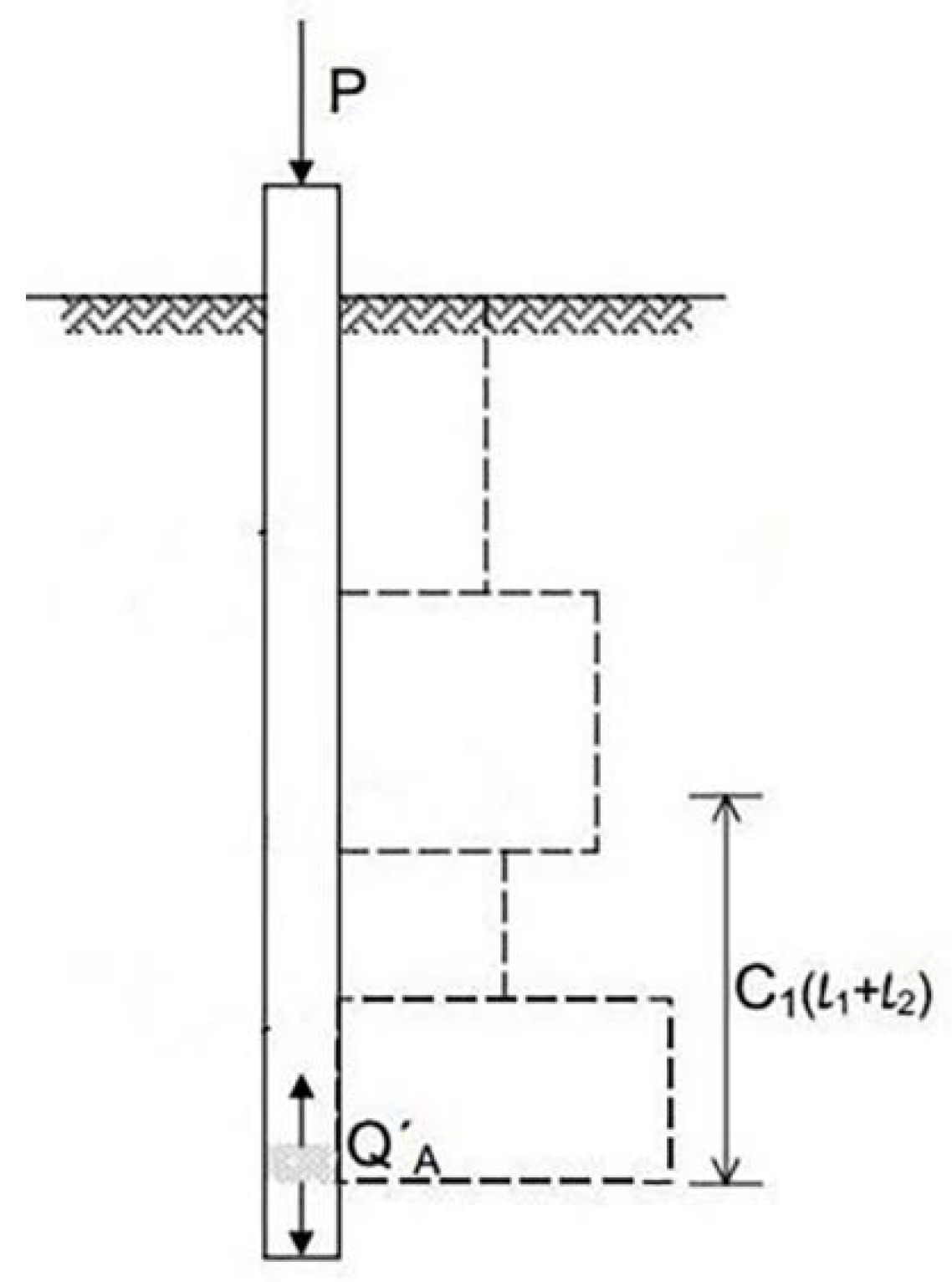
In the analyses, most of the soils were normally consolidated and elastic compression of the drilled shaft was considered. The effect of elastic compression on the drilled shaft, in the top-loaded drilled shaft, was calculated based on the pattern of developed side shear stress using Equation (1). where C1 is the centroid of unit side friction values for the strain gauge zones in the upper shaft unit, Q stands for the applied downward or upward load by the O-cell hydraulic jack, P is the applied axial load, L indicates the drilled shaft length, E represents the shaft’s modulus of the elasticity and A shows the cross-section of the drilled shaft in this equation.
δ = [ ( C 1 ) Q + ( 1 C 1 ) P ] L E A
Equation (2) was applied to include the effect of the elastic compression of the upper section of the pile.
δ = [ ( C 1 ) Q ] L E A
The developed side shear resistance along the pile length subjected to the axial load (P) or equal upward/downward load by O-cell (Q) is presented in Figure 14. To estimate the top-down elastic behavior, it is possible to subtract from the total for the section, as considered in Equation (1). The elastic compression is integrated in the measured upward response, as presented in Equation (2). The effect of the elastic compression during the downward load application by the Osterberg test can be ignored, as the procedure of the load application is downward is similar to the direction of the load application by the conventional top-down test. Therefore, the results are comparable, and there is no need for further calculation in the procedure of constructing equivalent load–displacement based on the Osterberg test’s downward curve. However, the upward application by the Osterberg test should be adjusted by considering the effect of the elastic compression to simulate the most realistic load–displacement curves compared to the top-down test.
During the Osterberg test, the unit side resistance was developed between 20 and 50 feet, where the mobilization of the existing caliche deposits was less than the developed side resistance during the theoretical conventional loading of the shaft. The measured side resistance during the conventional load was about 6ksf, which was almost twice the developed side resistance during the Osterberg test. Since the caliche was located far from the O-cell, it was not sufficiently mobilized to develop full capacity. The top-down load test reported more interaction of pile and caliche, as higher side resistance values were reported. The increase in caliche side resistance also affected the calculations of elastic shortening. By increasing the side resistance between 20 and 50 feet, the value of centroid for side resistance values “C” increased, as shown in Figure 15. Considering the new “C” value in the Equations (1) and (2) reduced the elastic shortening of the shaft. Therefore, the settlement was decreased based on the reported and constructed equivalent top-down load–settlement curves, while the load-bearing capacity of the drilled shaft for certain settlement values were increased.
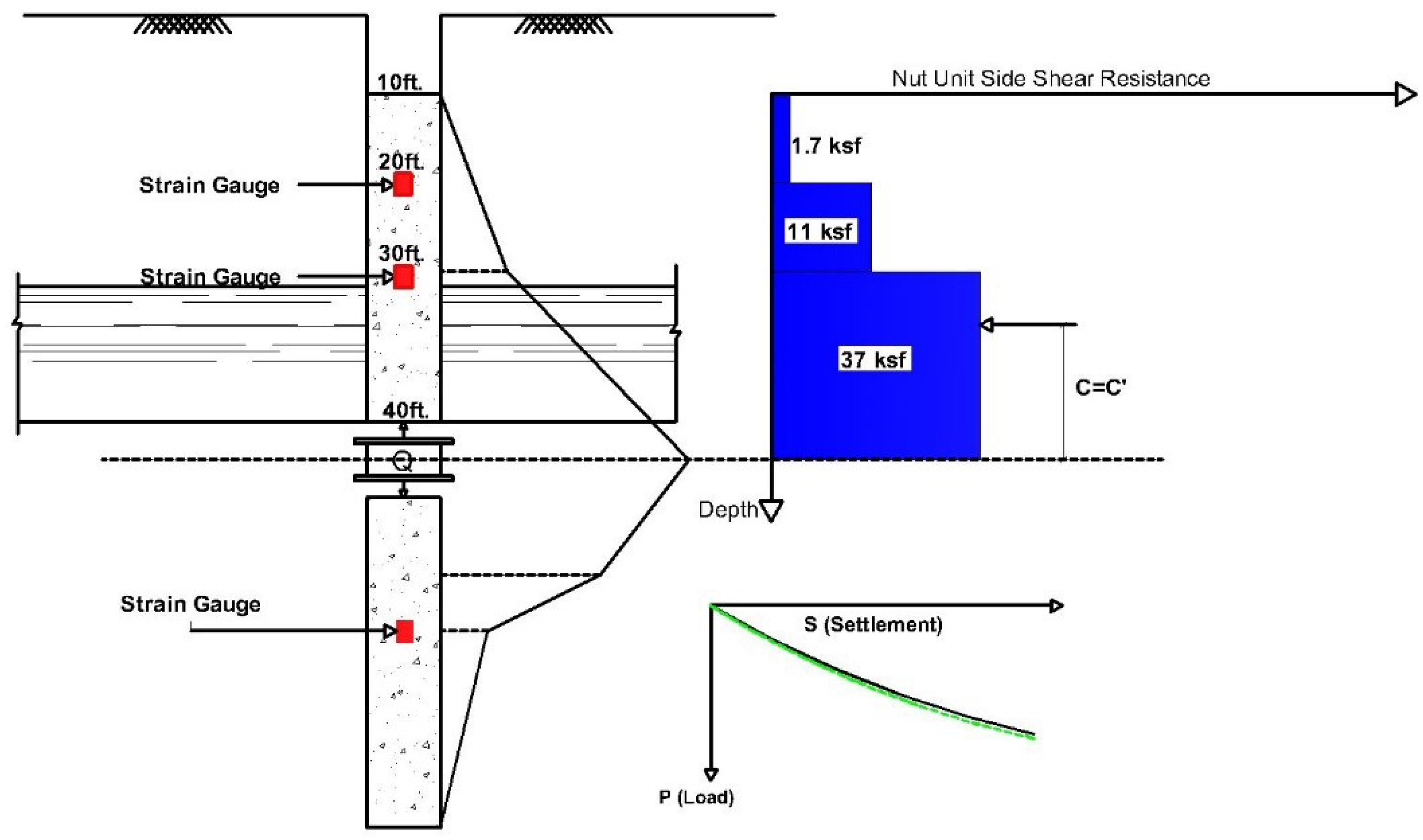
In Case Study II, other soil layers above caliche were partially developed to their failure capacity. During the upward load application, excessive movement between the soil layers and caliche deposit was recorded; however, an additional side resistance was not developed. The transferred load distribution, based on the load application by the top-down test in the caliche, was comparable to the Osterberg test results. Due to negligible changes in the side resistance based on the different loading directions, the C value remained constant. Subsequently, the load–settlement diagram for the test drilled shaft is similar for both loading directions, as presented in Figure 16.

5. Conclusions

The interaction of a drilled shaft with competent caliche deposits in heterogeneous soil was investigated following the results of full-scale Osterberg tests and the conducted finite element simulation. It was shown that the installed location of the O-cell hydraulic jack, with respect to the caliche layers, affects the interpretation of the test and reported load–settlement values.
The finite element analysis indicates that the preferred location for the installation of the O-cell in soil containing a competent caliche layer is the closest distance to this competent deposit. In this installation setting, the load–settlement curves resulting from the upward load application in the bidirectional Osterberg test are comparable to the downward load application of the conventional top-down test. Therefore, the measured values from the Osterberg test are more reliable with such an installation setting. The selection of a proper installation location for the O-cell alongside the pile length leads to considering the effect of caliche layers’ presence in the measurements of pile’s side resistance capacity, which, in turn, results in shorter required pile lengths.
Based on the outcome of this study, it is recommended to locate the most competent caliche layers in the soil profile prior to installation of the O-cell hydraulic jack, and to install this apparatus as close as possible to the competent caliche. This will enhance the design procedure of the drilled shaft in interaction with highly cemented soil layers, such as caliche deposits, and lead to a more economical pile design approach by considering the bearing capacity of caliche and reducing the required pile length.

Author Contributions

Conceptualization, R.A. and M.K.; Formal analysis, R.A., M.K., and V.F.; Software, R.A. and V.F.; Supervision, M.K.; Validation R.A. and V.F.; writing—original draft preparation, V.F. and R.A.; Data curation, R.A. and M.K.; Writing—review & editing, V.F. and M.K.; Funding acquisition, R.A. All authors have read and agreed to the published version of the manuscript.

Funding

The APC was funded by NOVA Geotechnical & Inspection Services, NV, USA.

Conflicts of Interest

The authors declare that they have no conflict of interest.

References

  1. Afsharhasani, R. Effect of Caliche on the Behavior of Drilled Shafts. Ph.D. Thesis, University of Nevada, Las Vegas, NV, USA, 2014. [Google Scholar]
  2. Kim, H.J.; Mission, J.L.; Park, T.W.; Dinoy, P.R. Analysis of Negative Skin-Friction on Single Piles by One-Dimensional Consolidation Model Test. Int. J. Civ. Eng. 2018, 16, 1445–1461. [Google Scholar] [CrossRef]
  3. Souza, D.T.G.; Adam, B. Load-Transfer Method for Piles under Axial Loading and Unloading. J. Geotech. Geoenviron. Eng. 2018, 144, 4017096. [Google Scholar] [CrossRef]
  4. Bughio, M.A.; Wang, P.; Meng, F.; Qing, C.; Kuzyakov, Y.; Wang, X.; Junejo, S.A. Neoformation of pedogenic carbonates by irrigation and fertilization and their contribution to carbon sequestration in soil. Geoderma 2016, 262, 12–19. [Google Scholar] [CrossRef]
  5. Hancock, G.R.; Kunkel, V.; Wells, T.; Martinez, C. Soil organic carbon and soil erosion—Understanding change at the large catchment scale. Geoderma 2019, 343, 60–71. [Google Scholar] [CrossRef]
  6. Brown, D.A.; Turner, J.P.; Castelli, R.J. Drilled Shafts: Construction Procedures and LRFD Design Methods; Federal Highway Administration: West Trenton, NJ, USA, 2010.
  7. Karakouzian, M.; Afsharhasani, R.; Kluzniak, B. Elastic analysis of drilled shaft foundations in soil profiles with intermediate caliche layers. Geotech. Spec. Publ. 2015, 256, 922–928. [Google Scholar]
  8. Pearthree, P.A. Geologic Excursions in Southwestern North America; Geological Society of America: Boulder, CO, USA, 2019. [Google Scholar]
  9. Fellenius, B.H.; Ann, T.S. Combination of O-cell Test and Conventional Head-Down Test. In Proceedings of the Art of Foundation Engineering Practice Congress 2010, West Palm Beach, FL, USA, 20–24 February 2010; Hussein, M.H., Anderson, J.B., Camp, W.M., Eds.; ASCE: Reston, VA, USA, 2010; pp. 240–259. [Google Scholar]
  10. Tehrani, F.S.; Salgado, R.; Prezzi, M. Analysis of axial loading of pile groups in multilayered elastic soil. Int. J. Geomech. 2016, 16, 04015063. [Google Scholar] [CrossRef]
  11. Pearlman, S.L. Pin Piles for Structural Underpinning. In Proceedings of the Ohio River Val Soils Semin XXXII Louisville, Louisville, KY, USA, 13 November 2001; pp. 2–12. [Google Scholar]
  12. Satvati, S.; Rowshanzamir, M.; Hejazi, M. Evaluation of the bearing capacity of shallow footing on soil slope reinforced by braid elements. In Proceedings of the 3rd Pan-American Conference on Geosynthetics, Miami, FL, USA, 10 April 2016. [Google Scholar]
  13. Farhangi, V.; Karakouzian, M.; Geertsema, M. Effect of micropiles on clean sand liquefaction risk based on CPT and SPT. Appl. Sci. 2020, 10, 3111. [Google Scholar] [CrossRef]
  14. Farhangi, V.; Karakouzian, M. Design of Bridge Foundations Using Reinforced Micropiles. In Proceedings of the International Road Federation Global R2T Conference & Expo, Las Vegas, NV, USA, 19–22 November 2019; pp. 78–83. [Google Scholar]
  15. Choi, W.; Kim, G.; Kim, I.; Kyung, D.; Lee, J. Compressive Load-Carrying Behavior of Inclined Micropiles Installed in Soil and Rock Layers. Int. J. Geomech. 2020, 20, 04020147. [Google Scholar] [CrossRef]
  16. Jafari, K.; Tabatabaeian, M.; Joshaghani, A.; Ozbakkaloglu, T. Optimizing the mixture design of polymer concrete: An experimental investigation. Constr. Build. Mater. 2018, 167, 185–196. [Google Scholar] [CrossRef]
  17. Farhangi, V.; Karakouzian, M. Effect of fiber reinforced polymer tubes filled with recycled materials and concrete on structural capacity of pile foundations. Appl. Sci. 2020, 10, 1554. [Google Scholar] [CrossRef] [Green Version]
  18. Haberfield, C.M.; Lochaden, A.L.E. Analysis and design of axially loaded piles in rock. J. Rock Mech. Geotech. Eng. 2019, 11, 535–548. [Google Scholar] [CrossRef]
  19. Toghroli, A.; Mehrabi, P.; Shariati, M.; Trung, N.T.; Jahandari, S.; Rasekh, H. Evaluating the use of recycled concrete aggregate and pozzolanic additives in fiber-reinforced pervious concrete with industrial and recycled fibers. Constr. Build. Mater. 2020, 252, 118997. [Google Scholar] [CrossRef]
  20. Jarrah, M.; Najafabadi, E.P.; Khaneghahi, M.H.; Oskouei, A.V. The effect of elevated temperatures on the tensile performance of GFRP and CFRP sheets. Constr. Build. Mater. 2018, 190, 38–52. [Google Scholar] [CrossRef]
  21. Jahandari, S.; Saberian, M.; Tao, Z.; Mojtahedi, S.F.F.; Li, J.; Ghasemi, M.; Rezvani, S.; Li, W. Effects of saturation degrees, freezing-thawing, and curing on geotechnical properties of lime and lime-cement concretes. Cold Reg. Sci. Technol. 2019, 160, 242–251. [Google Scholar] [CrossRef]
  22. Akbarzadeh Bengar, H.; Shahmansouri, A.A. A new anchorage system for CFRP strips in externally strengthened RC continuous beams. J. Build. Eng. 2020, 30, 101230. [Google Scholar] [CrossRef]
  23. Jafari, K.; Toufigh, V. Experimental and analytical evaluation of rubberized polymer concrete. Constr. Build. Mater. 2017, 155, 495–510. [Google Scholar] [CrossRef]
  24. Jazaei, R.; Karakouzian, M.; O’Toole, B.; Moon, J.; Gharehdaghi, S. Failure mechanism of cementitious nanocomposites reinforced by multi-walled and single-walled carbon nanotubes under splitting tensile test. In Proceedings of the ASME 2018 International Mechanical Engineering Congress and Exposition, Pittsburgh, PA, USA, 9–15 November 2018. [Google Scholar]
  25. Sabzi, J.; Esfahani, M.R.; Ozbakkaloglu, T.; Farahi, B. Effect of concrete strength and longitudinal reinforcement arrangement on the performance of reinforced concrete beams strengthened using EBR and EBROG methods. Eng. Struct. 2020, 205, 110072. [Google Scholar] [CrossRef]
  26. Satvati, S.; Nahvi, A.; Cetin, B.; Ashlock, J.C.; Jahren, C.T.; Ceylan, H. Performance-based economic analysis to find the sustainable aggregate option for a granular roadway. Transp. Geotech. 2020, 100410. [Google Scholar] [CrossRef]
  27. Gu, L.; Wang, Z.; Huang, Q.; Ye, G.; Zhang, F. Numerical investigation into ground treatment to mitigate the permanent train-induced deformation of pile-raft-soft soil system. Transp. Geotech. 2020, 24. [Google Scholar] [CrossRef]
  28. Kazemi, M.; Hajforoush, M.; Talebi, P.K.; Daneshfar, M.; Shokrgozar, A.; Jahandari, S.; Saberian, M.; Li, J. In-situ strength estimation of polypropylene fibre reinforced recycled aggregate concrete using Schmidt rebound hammer and point load test. J. Sustain. Cem. Mater. 2020, 160, 343–356. [Google Scholar] [CrossRef]
  29. Asem, P. Load-displacement response of drilled shaft tip in soft rocks of sedimentary origin. Soils Found. 2019, 59, 1193–1212. [Google Scholar] [CrossRef]
  30. Berisavljević, D.; Filipović, V.; Stanisavljević, N.; Berisavljević, Z. Experimental analysis of bi-directional pile static load test. Ce/Papers 2018, 2, 415–420. [Google Scholar] [CrossRef]
  31. Bohn, C.; Lopes dos Santos, A.; Frank, R. Development of axial pile load transfer curves based on instrumented load tests. J. Geotech. Geoenviron. Eng. 2017, 143, 04016081. [Google Scholar] [CrossRef]
  32. Li, Y.; Zhu, X.; Chen, L.; Zhou, T. Load Transfer Calculation and Analysis of Large-Diameter Bored Piles According to Rules Based on Test Pile Measurement. J. Highw. Transp. Res. Dev. 2018, 12, 28–36. [Google Scholar] [CrossRef]
  33. Seo, H.; Moghaddam, R.B.; Lawson, W.D. Assessment of methods for construction of an equivalent top loading curve from O-cell test data. Soils Found. 2016, 56, 889–903. [Google Scholar] [CrossRef]
  34. Asem, P.; Gardoni, P. A load-transfer function for the side resistance of drilled shafts in soft rock. Soils Found. 2019, 59, 1241–1259. [Google Scholar] [CrossRef]
  35. Ng, T.T.; Meyers, R. Side resistance of drilled shafts in granular soils investigated by DEM. Comput. Geotech. 2015, 68, 161–168. [Google Scholar] [CrossRef]
  36. Zhou, Z.; Dong, Y.; Jiang, P.; Han, D.; Liu, T. Calculation of Pile Side Friction by Multiparameter Statistical Analysis. Adv. Civ. Eng. 2019, 2019, 2638520. [Google Scholar] [CrossRef]
  37. Zhou, J.; Zhou, C.; Feng, Q.; Gao, T. Analytical Model for Load-Transfer Mechanism of Rock-Socketed Drilled Piles: Considering Bond Strength of the Concrete-Rock Interface. Int. J. Geomech. 2020, 20. [Google Scholar] [CrossRef]
  38. ASTM. Standard Test Methods for Deep Foundations under Static Axial Compressive Load, 8th ed.; Astm D1143/D1143M-07, American Society for Testing and Materials, Annual Book of ASTM Standards; ASTM International: West Conshohocken, PA, USA, 2013. [Google Scholar]
  39. Xu, M.; Ni, P.; Mei, G.; Zhao, Y. Load-settlement behaviour of bored piles with loose sediments at the pile tip: Experimental, numerical and analytical study. Comput. Geotech. 2018, 102, 92–101. [Google Scholar] [CrossRef]
  40. DD3550M ASTM, Standard Practice for Thick Wall, Ring-Lined, Split Barrel, Drive Sampling of Soils; ASTM: West Conshohocken, PA, USA, 2017.
  41. ASTM D4318-00, Standard Test Methods for Liquid Limit, Plastic Limit, and Plasticity Index of Soils; ASTM: West Conshohocken, PA, USA, 2018.
  42. ASTM D3080, Standard Test Method for Direct Shear Test of Soils under Consolidated Drained Conditions; ASTM: West Conshohocken, PA, USA, 2011.
  43. Abedin, M.; Mehrabi, A.B. Novel approaches for fracture detection in steel girder bridges. Infrastructures 2019, 4, 42. [Google Scholar] [CrossRef] [Green Version]
  44. Valikhani, A.; Jahromi, A.J.; Mantawy, I.M.; Azizinamini, A. Numerical modelling of concrete-to-UHPC bond strength. Materials 2020, 13, 1379. [Google Scholar] [CrossRef] [Green Version]
  45. Boushehri, R.; Estahbanati, S.H.; Hosseini, S.M.M.M.; Soroush, A. Influence of Reinforcement Parameters on the Seismic Response of Reinforced Earth Dams. In Proceedings of the Geo-Congress 2020: Engineering, Monitoring, and Management of Geotechnical Infrastructure, Minneapolis, MN, USA, 25–28 February 2020; pp. 637–649. [Google Scholar]
  46. Estahbanati, S.H.; Boushehri, R.; Soroush, A.; Ghasemi-Fare, O. Numerical study of the effects of deep excavations on dynamic performance of buried pipelines. In Proceedings of the Geo-Congress 2020: Engineering, Monitoring, and Management of Geotechnical Infrastructure, Minneapolis, MN, USA, 25–28 February 2020; pp. 86–94. [Google Scholar]
  47. Osterberg, J.; Pepper, S. A new simplified method for load testing drilled shafts. Found Drill. 1984, 23, 9–11. [Google Scholar]
  48. Asem, P. The effect of expansive concrete on the side resistance of sockets in weak rock. Soils Found. 2020, 60, 274–282. [Google Scholar] [CrossRef]
  49. Plaxis, B. PLAXIS 2D Version 8.2-Finite Element Code for Soil and Rock Analysis; AA Balkema: Delft, The Netherlands, 2004. [Google Scholar]
  50. Asgharzadeh, A.; Nazari Tiji, S.A.; Esmaeilpour, R.; Park, T.; Pourboghrat, F. Determination of hardness-strength and -flow behavior relationships in bulged aluminum alloys and verification by FE analysis on Rockwell hardness test. Int. J. Adv. Manuf. Technol. 2020, 106, 315–331. [Google Scholar] [CrossRef]
  51. Zamanian, S.; Hur, J.; Shafieezadeh, A. Significant variables for leakage and collapse of buried concrete sewer pipes: A global sensitivity analysis via Bayesian additive regression trees and Sobol’ indices. Struct. Infrastruct. Eng. 2020. [Google Scholar] [CrossRef]
  52. Beizaei, M.; Hosseininia, E.S.; Morovatdar, A. Investigating the Practical Conditions to Utilize Brick Stair Wall Method as a Supporting Structure in Urban Excavation. In Proceedings of the Geo-Congress 2020: Engineering, Monitoring, and Management of Geotechnical Infrastructure, Minneapolis, MN, USA, 25–28 February 2020; pp. 429–439. [Google Scholar]
  53. Eslami, M.; Namba, H. Elasto-plastic behavior of composite beam connected to RHS column, experimental test results. Int. J. Steel Struct. 2016, 16, 901–912. [Google Scholar] [CrossRef]
  54. Liang, J.; Nie, X.; Masud, M.; Li, J.; Mo, Y.L. A study on the simulation method for fatigue damage behavior of reinforced concrete structures. Eng. Struct. 2017, 150, 25–38. [Google Scholar] [CrossRef]
  55. Dehghani, N.L.; Rahimi, M.; Shafieezadeh, A.; Padgett, J.E. Parameter Estimation of a Fractional Order Soil Constitutive Model Using KiK-Net Downhole Array Data: A Bayesian Updating Approach. Geotech. Spec. Publ. 2020, 2020, 346–356. [Google Scholar]
Figure 1. Measured plasticity index variation based on the depth values in the project.
Applsci 10 06169 g001
Figure 2. Measured unconfined compressive strength (UCS) triaxial test results of the caliche cores.
Applsci 10 06169 g002
Figure 3. Measurements of the Standard Penetration Test and California Split Spoon Sampler in the soil containing competent caliche layers.
Applsci 10 06169 g003
Figure 4. Location of the 30 reported bidirectional Osterberg tests. The full-scale tests were conducted in the presence of highly cemented caliche layers in the soil profile.
Applsci 10 06169 g004
Figure 5. O-cell hydraulic jack location with respect to the existing competent caliche layer scenarios.
Applsci 10 06169 g005
Figure 6. Comparison of Upward and Downward Settlement based on the O-cell location in the drilled shaft.
Applsci 10 06169 g006
Figure 7. Load transfer distribution of the upward and downward loading by O-cell and top-down load application in the soil profile containing competent caliche layers, based on the finite element simulation of Case Study I.
Applsci 10 06169 g007
Figure 8. t–z stiffness curve for the constructed top-down load along with the upward and downward axial load finite element simulation in Case Study I.
Applsci 10 06169 g008
Figure 9. Constructed top-down curves based on the proposed back analysis, along with the conventional method according to the Osterberg assumptions, Case Study I.
Applsci 10 06169 g009
Figure 10. Finite element simulation based on the reported bidirectional test results, Case Study II.
Applsci 10 06169 g010
Figure 11. Load transfer distribution of the upward and downward loading, along with the top-down load application in the soil containing competent caliche layers, based on the finite element simulation of Case Study II.
Applsci 10 06169 g011
Figure 12. t–z stiffness curve for the constructed top-down load, along with the upward and downward axial load finite element simulation in Case Study II.
Applsci 10 06169 g012
Figure 13. Constructed top-down curves based on the proposed back analysis, along with the conventional method according to the Osterberg assumptions, Case Study II.
Applsci 10 06169 g013
Figure 14. Developed Side Shear Resistance.
Applsci 10 06169 g014
Figure 15. Unit Side Resistance and Load–settlement Comparison for O-cell test and Conventional Test (Case Study I).
Applsci 10 06169 g015
Figure 16. Unit side resistance and load–settlement comparison for the Osterberg test and conventional test (Case Study II).
Applsci 10 06169 g016
Table 1. Geometries of the drilled shaft, caliche layers and reported bidirectional loads based on 30 Osterberg tests.
Test ID(Caliche Depth *, Caliche Thickness)
(ft)
Shaft Diameter (in)Shaft Length (ft)O-Cell Installation Depth (ft)Top of the Shaft (ft) Maximum O-Cell Load (kips)
TP-1(18, 3), (24, 10), (39, 3), (47, 6)4810650206748
TP-2(21, 15), (42, 6), (53, 3), (61, 8), (77, 8)481053553964
TP-3(11, 8), (33, 3), (44, 7)481176054722
TP-4(14, 6), (54, 2), (66, 1)481126094287
TP-5(13, 7), (31, 4), (71, 4)489739147086
TP-6,7,8(23, 7), (34, 5), (56, 3)481284305476
TP-9,10(8, 1), (11, 1), (13, 4), (21, 1), (29, 1)4812280,120453077
TP-11(30, 10), (55, 8)3610055301959
TP-12(29, 7), (55, 4), (66, 7), (90, 3), (123, 4), (146, 4)4810050403544
TP-13(12, 6), (26, 8), (51, 4), (126, 4)489945303684
TP-14(12, 6), (26, 8), (51, 4), (126, 4)489945305950
TP-15(8, 1), (40, 1), (43, 2)4812378126164
TP-16(36, 51), (51, 1), (60, 2)4812365106172
TP-17(23, 18), (50, 5), (68, 9)4210040106128
TP-18(10, 1), (13, 1), (52, 4), (65, 4)48625783068
TP-19(13, 4), (30, 6), (60, 2), (69, 1)4810350,80193316
TP-20(18, 16), (36, 16), (92, 4)429035107358
TP-21(6, 14)427430156400
TP-22(5, 12)489680154800
TP-23(6, 10)4810054147202
TP-24(4, 5)43914282901
TP-25(6, 1), (16, 1)41905004098
TP-26(7, 2)36794113133
TP-27(6, 6), (27, 3), (45, 4)427035104088
TP-28(25, 2)42732744914
TP-29(14, 2), (17, 2), (25, 2), (28, 1), (31, 2), (50, 1), (70, 1)4510440106400
TP-30(19, 2), (35, 3), (55, 7)429050152978
* Depths of Caliche layer is measured from top of this layer to the ground surface level.
Table 2. Material Properties, Case Study I.
Material Properties of Sensitivity Case Study I
ParameterUnitConcreteSandy ClayCaliche
Material Model Linear ElasticMCMC
Drainage condition DrainedDrainedDrained
Dry Unit Weightklb/ft30.150.120.16
Saturated Unit Weightklb/ft30.150.130.16
Young’s Modulusklb/ft2500,0004000280,000
Poisson’s ratio 0.150.30.2
Cohesionklb/ft2-110
Friction AngleDegree-2835
Interface Material
Material ModelUnit MCMC
Drainage condition DrainedDrained
Dry Unit Weightklb/ft3 0.120.16
Saturated Unit Weightklb/ft3 0.130.16
Young’s Modulusklb/ft2 4000280,000
Poisson’s ratio 0.30.2
Cohesionklb/ft2 0.310
Friction AngleDegree 2335
Table 3. Material Properties, Case Study II.
Material Properties of Sensitivity Case Study II
ParameterUnitConcreteClayey SandSandy ClayCemented Sand and GravelCalicheStiff Clay
Material Model Linear ElasticMCMCMCMCMC
Drainage condition DrainedDrainedDrainedDrainedDrainedDrained
Dry Unit Weightklb/ft30.150.120.120.120.160.13
Saturated Unit Weightklb/ft30.150.120.130.130.160.13
Young’s Modulusklb/ft2445,600100015003000560,0001000
Poisson’s ratio 0.150.30.30.30.20.4
Cohesionklb/ft2-0.810.1200.2
Friction AngleDegree-3528453530
Interface Material
Material ModelUnit MCMCMCMMC
Drainage condition DrainedDrainedDrainedDrainedDrained
Dry Unit Weightklb/ft3 0.120.120.120.160.13
Saturated Unit Weightklb/ft3 0.120.130.130.160.13
Young’s Modulusklb/ft2 100015003000560,0001000
Poisson’s ratio 0.30.30.30.20.4
Cohesionklb/ft2 0.810.1200.2
Friction AngleDegree 2223302818