Article

Impact of Thermomechanical Fatigue on Microstructure Evolution of a Ferritic-Martensitic 9 Cr and a Ferritic, Stainless 22 Cr Steel

Forschungszentrum Juelich GmbH, Institute of Energy and Climate Research (IEK), Microstructure and Properties of Materials (IEK-2), 52425 Jülich, Germany
*
Author to whom correspondence should be addressed.
Independent Researcher, 52425 Jülich, Germany.
Appl. Sci. 2020, 10(18), 6338; https://doi.org/10.3390/app10186338
Submission received: 17 August 2020 / Revised: 3 September 2020 / Accepted: 10 September 2020 / Published: 11 September 2020
(This article belongs to the Special Issue Thermomechanical Properties of Steel)

Abstract

:
The highly flexible operation schemes of future thermal energy conversion systems (concentrating solar power, heat storage and backup plants, power-2-X technologies) necessitate increased damage tolerance and durability of the applied structural materials under cyclic loading. Resistance to fatigue, especially thermomechanical fatigue and the associated implications for material selection, lifetime and its assessment, are issues not considered adequately by the power engineering materials community yet. This paper investigates the principal microstructural evolution, damage and failure of two steels in thermomechanical fatigue loading: Ferritic-martensitic grade 91 steel, a state of the art 9 wt % Cr power engineering grade and the 22 wt % Cr, ferritic, stainless Crofer® 22 H (trade name of VDM Metals GmbH, Germany; under license of Forschungszentrum Juelich GmbH) steel. While the ferritic-martensitic grade 91 steel suffers pronounced microstructural instability, the ferritic Crofer® 22 H provides superior microstructural stability and offers increased fatigue lifetime and more forgiving failure characteristics, because of innovative stabilization by (thermomechanically triggered) precipitation of fine Laves phase particles. The potential for further development of this mechanism of strengthening against fatigue is addressed.

1. Introduction

The preservation of resources, along with maximization of economic success by improvement of plant efficiency, were the driving forces in the past development of advanced thermal power conversion equipment. The German Energiewende (engl.: energy challenge, i.e., the intended transition of electricity supply towards regenerative sources of power) poses great challenges in terms of load flexibility and thermal cycling capability of the employed structural materials [1,2,3], because novel conversion technologies (e.g., concentrating solar power, heat storage and backup plants) will face highly challenging, fluctuating operation conditions. Besides the implementation of heat storage, the minimum load capability of thermal power conversion equipment will decrease, while start-up times and load ramps will increase to ensure grid stability by balancing fluctuating regenerative power sources (like wind and solar) [1].
Traditional criteria in the design of power engineering equipment (and in consequence structural materials) were for example an expected lifetime of appr. 200,000 h, including 200 hot starts (defined by an idle period of less than 8 h), 50 warm starts (less than 72 h of idle) and two cold starts per year. In contrast to this, future design criteria are still widely undefined, but regarding cyclic operation, up to 10–500 hot starts (<8 h of idle), 50–120 warm starts (up to 48 h of idle) and two–twenty cold starts (up to 120 h of idle) per year are considered realistic [1].
Only experimental studies on the microstructural stability and performance of typical, low-cost power engineering structural steel grades are published so far [4,5,6,7,8,9,10,11,12,13,14,15,16]. This paper outlines an approach to increased microstructural stability of prospective low-cost structural steel for the application under thermomechanical fatigue (TMF) loading.

2. Materials and Methods

2.1. Ferritic-Martensitic 9 Cr and Ferritic, Stainless 22 Cr Steel

Grade 91 is a standard, so-called 9 wt % Cr advanced ferritic-martensitic (AFM) steel, widely applied for structural purposes in power engineering. It features tempered martensite structure in the as-delivered state and is strengthened by solid solution and precipitation of MX (M: V, Nb; X: N), mainly located at lath and M23C6 (M: Mo, Cr) particles, preferentially located at prior austenite grain boundaries (PAGBs) [17,18,19]. The grade 91 material applied in this study was taken from a pipe section (Ø outer = 160 mm, tw = 20 mm), manufactured by Vitkovice Steel, CZ according to ASTM A335 specifications. Austenitizing and tempering were executed at 1050 °C/0.5 h/air-cooling and 750 °C/1 h/air-cooling. The resulting as-received microstructure is depicted in Figure 1.
Crofer®22 H (X1CrWNbTiLa22-2, W.-Nr. 1.4,755 [20]) is a 22 wt % Cr, stainless, fully ferritic steel, originally developed as a low-cost, metallic interconnector material for light-weight design [21,22] solid oxide fuel cell stacks by Forschungszentrum Juelich GmbH, Germany, in cooperation with VDM Metals GmbH, Germany. It is produced by VDM Metals GmbH by vacuum induction melting (VIM) and delivered in the solution in an annealed (1050 °C/5 + minutes, depending on section thickness/rapid air-cooling) state. It precipitates small (Fe, Cr, Si)2 (Nb, W)-Laves phase particles (Figure 2) [23,24], which effectively strengthen the material [20,25,26,27], during application in the temperature range from 600–900 °C. Thermomechanically induced precipitation of the Laves phase particles [28,29,30,31,32] plays a significant role in the fatigue performance of this type of steel, too. Furthermore, Crofer®22 H offers excellent resistance to corrosion in steam and CO/CO2-containing atmospheres, based on the formation of a protective, duplex Cr2O3/(Mn, Cr)3O4 layer at the component surface [23]. For these reasons, advanced Laves phase strengthened steels are considered candidate alloys for future power conversion equipment of higher efficiency [32] and increased operational flexibility [33]. A typical microstructure is displayed in Figure 2. Besides precipitation of small Laves phase particles, the formation of particle-free zones (PFZs), preferentially along high angle grain boundaries (HAGB) [33,34], is a typical microstructural feature of this steel type.
From a metallurgical point of view, the main difference between the two materials besides microstructure and strengthening precipitate species are the differing solid solution contents of chromium, tungsten and molybdenum. The chemical compositions of the ferritic-martensitic grade 91 and the fully ferritic, stainless Crofer®22 H steels are summarized in Table 1.

2.2. Mechanical Testing

Strain-controlled thermomechanical fatigue (according to the European Code-of-Practice [35]) experiments were carried out, applying cylindrical specimens (gauge length/diameter ratio: 15/7 mm) and utilizing servo-hydraulic fatigue testing machines with inductive heating. Specimen temperature was controlled by Type R sling thermocouples attached to the center of the gauge length. At a controlled heating/cooling rate of 10 Ks−1 out-of-phase (oop) cycles were performed in the temperature range from 250 to 650 °C. Specimen cooling by compressed air was initiated immediately after reaching the maximum temperature, i.e., holding times at Tmax. were excluded, to minimize creep deformation as far as possible. The thermal expansion (εth.) of the materials was completely obstructed (i.e., so-called 100% oop cycles were performed, Rε, mech = −∞) by mechanical strain (εmech.), applied by the testing machine, during heating and cooling. The majority of experiments were interrupted at the given number of cycles to provide TMF-loaded material for in-depth microstructure investigation. Note that executing TMF experiments with 100% obstruction of thermal strain at different materials causes deviations of the effective strain ranges, because of differing thermal expansions of the materials. In our case, the higher Cr-content of Crofer®22 H (Table 1) results in a, compared to P91 (0.56%), slightly lower strain range of 0.49%. This was deliberately applied, because this difference occurs in real life application in exactly the same way.

2.3. Microstructural Observation

Samples, cut from the mechanical testing specimens, were embedded in epoxy resin, ground and polished to a sub-micron finish for microstructural examination. Samples for the analysis of Laves phase precipitation in Crofer®22 H steel were slightly etched at 1.5 V in 5% H2SO4 to increase the particle/matrix contrast. Details on specimen preparation are given in [36]. High-resolution micrographs were acquired by a Zeiss Merlin field emission scanning electron microscope (acceleration voltage: 10 kV). Electron backscatter diffraction (EBSD) was utilized to characterize the orientation relations of individual grains of the Fe_bcc matrix and the analysis of localized deformation. A misorientation angle of >3° was applied for the definition of fatigue-induced sub-grain boundaries. The generated micrographs were post-processed, binarized and quantitatively analyzed applying the commercial software package AnalysisPro® with regard to grain size evolution and the freely available package ImageJ [37] concerning precipitate size evolution, following the method outlined in [38].

3. Results and Discussion

3.1. Thermomechanical Fatigue Behavior

Owing to the different alloying philosophies, the two materials yield decisive differences in the initial and damage phase as well as in fatigue life, but almost comparable stress range in the stable phase of the fatigue life curve.
Figure 3a displays typical thermomechanical fatigue life curves of the ferritic-martensitic grade 91 and ferritic Crofer®22 H steels from oop cycles with complete (100%) obstruction of thermal strain (i.e., the specimen faces compressive stress during heating up to the hot end of the cycle and tensile stress during cooling down to the cold end). Figure 3b in detail depicts the initial phases of both the materials up to 1200 cycles. In Figure 3c,d the associated stress-strain hysteresis loops are given.
Representative for AFM steels [4,5,6,33], grade 91 is characterized by a comparatively high initial strain range, which is caused by increased dislocation density from martensitic transformation during heat treatment. However, during the first appr. 1000 TMF cycles, the recorded stress range continuously decreases by typically (cf. grade 92 and MarBN-Type steel in [33]) one third of the initial value (Figure 3b). The main part of this drop takes place at the hot ends (i.e., at compressive stress) of the first 10 cycles, which is clearly observable from the hysteresis loops (cf. cycles # 1 vs. # 10 in Figure 3c). Up to 250 cycles, the further decrease localizes almost symmetrically to both ends of the loops (cf. cycles # 10 vs. # 250 in Figure 3c). Towards higher cycle numbers, just slight further changes of the hysteresis loops become evident (cf. cycles # 250 vs. # 1250 in Figure 3c) until a stable phase of slightly negative slope is entered at around 1000 cycles. The material finally reaches the damage phase (Figure 3a: >1962 cycles, Table 2), after which failure is characterized by a comparatively steep drop in stress range.
During the initial phase, Crofer®22 H strengthens by appr. 25% (Figure 3a,b) and reaches a peak in stress range at about 35 cycles (Figure 3d), then drops down by about 5% up to appr. 400 cycles, where it enters the stable stage, which lasts up to about Nd = 1993 cycles. Despite of the lower effective strain range, Crofer®22 H reaches a slightly higher stable stress range (Figure 3) and mean stress (Table 2) levels than P91. In the damage phase, it exhibits diminished decrease in stress range per cycle (Figure 3a), which in consequence leads to prolonged TMF lifetime (Nf = 4091 cycles) in comparison to P91. To consider this difference in tolerance to damage (represented by the slope difference of the fatigue curves of both materials in the failure range, cf. Figure 3a) fatigue lifetime was determined from the intersection of linear approximations to the stable (deviation of the fatigue curve from this approximation determines Nd) and the failure curve sections of the fatigue curve (cf. Crofer®22 H curve in Figure 3a).
A comparison of damage ranges (i.e., the relation of technical lifetime Nf to damage initiation Nd, Table 2) demonstrates the more forgiving character of the ferritic, Laves phase-strengthened Crofer®22 H steel concerning initiation and propagation of short cracks in thermomechanical fatigue loading. Mathematical integration of the fatigue hysteresis loop (Figure 3c,d) yields the cumulated deformation energy induced into the material. In the stable range of the fatigue curve, a single cycle in the case of P91 calculates to 1.145 MJ/m3 (@ Nf/2 = 1486 cycles). Despite the higher stress range and mean stress, Crofer®22 H with 1.081 MJ/m3 (@ Nf/2 = 2045 cycles) yields lower deformation energy per cycle, because of its lower thermal expansion coefficient. Damage is induced later than in martensitic P91 and it reaches 28% longer fatigue lifetime along with 21% higher cumulated deformation energy until failure (Table 2).

3.2. Quantititative Microstructure Assessment

The cyclic softening of ferritic-martensitic steels in fatigue loading is caused by the rearrangement of the initially high dislocation density to a dislocation cell structure of lower internal stress [7,8]. Furthermore, the inability of coarsening precipitates to pin the martensitic lath boundaries contributes to recrystallization [7,8]. Degradation of a tempered martensite lath structure because of prolonged fatigue loading thus is a well-documented phenomenon. For this reason, dislocation density and precipitate size evolution of P91 is not covered by our study. Nevertheless, it should be mentioned that sub-grain activity during fatigue loading of ferritic-martensitic steel is ambiguous: While in isothermal fatigue subgrain coarsening is reported [8,9,10], several authors documented, what we like to call polygonization rather than recrystallization in thermomechanical fatigue [4,11,12,13,14]. Obviously, the manifestations of sub-grain activity do depend on the type of fatigue cycle, which governs the balance of dislocation creating (plasticization) and annihilating (temperature, time) parameters.
The differences in TMF behavior, outlined in Section 3.1, can only be explained by detailed microstructure analysis with regard to the characteristic experimental phases. In the case of P91, the examination was focused on the question if polygonization could be utilized for material damage and lifetime assessment, i.e., if it correlates to the initial drop in stress range or rather to damage initiation and final failure. In the case of the ferritic Crofer® 22 H, no microstructure information was available to explain the shape of the fatigue curve, especially the peak after initial strengthening (Figure 3a,b) and the minimized decrease in stress range per cycle in the damage regime. Investigation thus concentrated on the description of the strengthening mechanisms and deriving recommendations for potential further optimization of this alloy type.

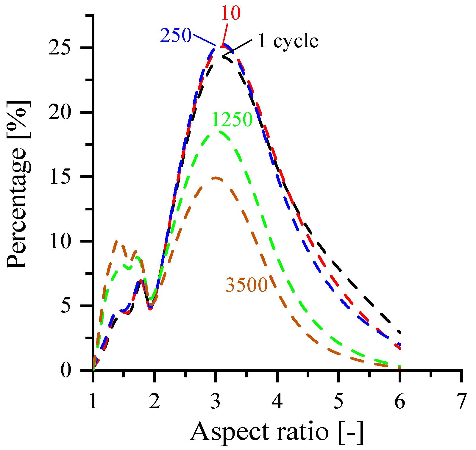
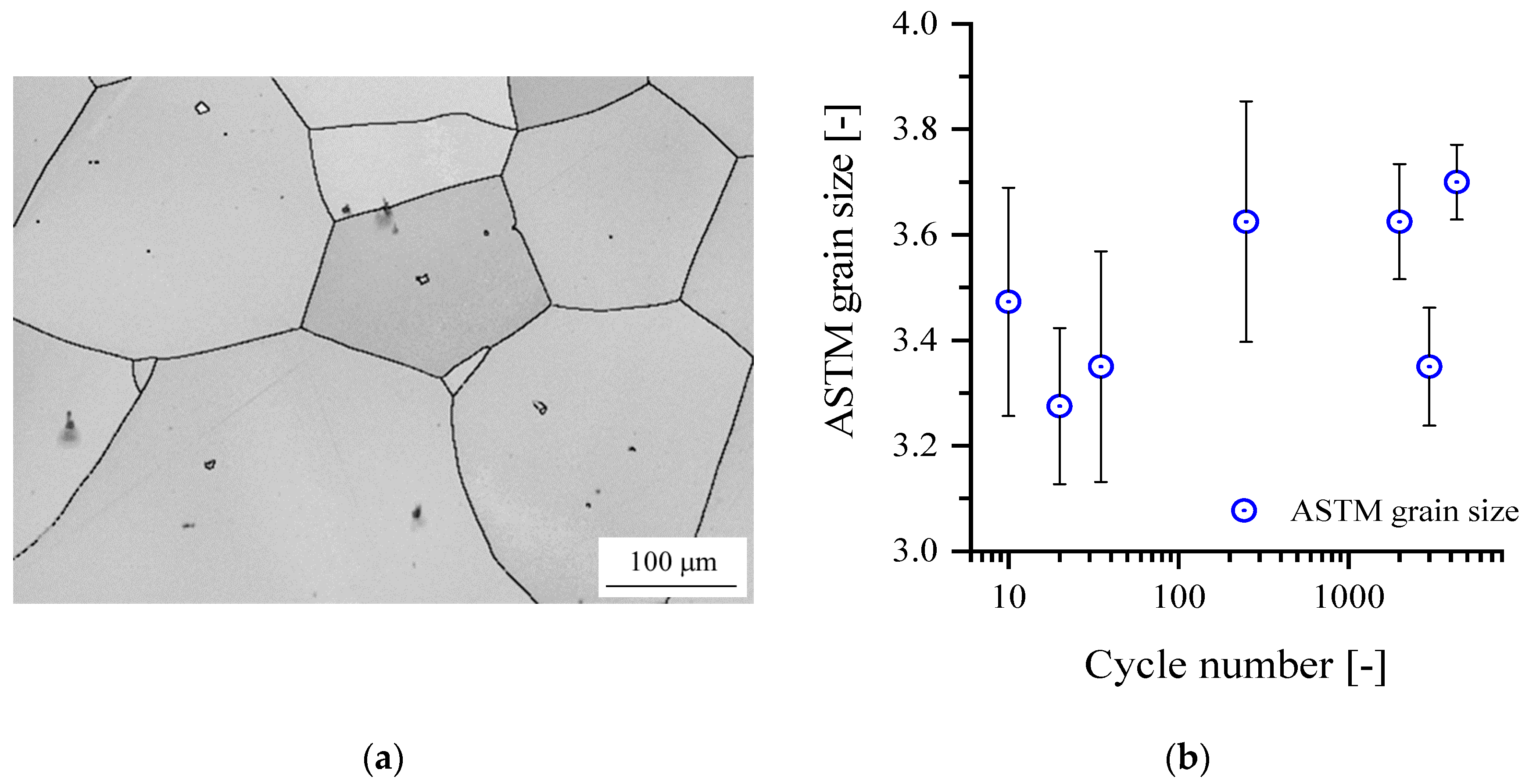
3.3. Stability of Grain Structure

The steep drop in stress range of P91 during the first 10 cycles (Figure 3a,b) does not correlate to any visible sub-grain activity (cf. Figure 4a: 0 cycles to Figure 4b: 10 cycles) within the martensite lath structure. The decrease in stress range for this reason is caused by recovery of excess dislocations at the hot ends of the TMF cycles (cf. Figure 3c) alone. The start of degradation of the martensite lath structure appears in transition from the initial to the stable stress range section of the fatigue curve and becomes progressive with an increasing number of cycles (cf. Figure 4c: 250 cycles and 4d: 1250 cycles). Cyclic plasticization causes polygonization of the martensite lath structure. The resulting grain size distribution rather approximates that of the initial martensite lath width distribution (cf. Figure 4a–d) than the prior austenite grain size, which is in accordance with the results of [4,11,12,13,14] acquired at other AFM steels under TMF loading.
The iron- and chromium-containing mixed oxides within the crack do not play a role in microstructural degradation of the bulk material and the initiation of short fatigue cracks. A possible effect on the propagation of long fatigue cracks and residual lifetime is the subject of ongoing research.
The evolution of grain aspect ratio AR (ratio of grain length to grain width, Figure 5) of the martensite laths is the most suitable microstructural feature for quantification of this phenomenon. Elongated martensite laths of AR ≥ 3 (clearly observable after 0, 10 and 250 cycles, Figure 4a–c or Figure 5) gradually disappear with an increasing number of cycles and become substituted by smaller, almost globular sub-grains of AR → 1 (Figure 4d,e: 1250, 3500 cycles, Figure 5). This phenomenon is not restricted to the strongly deformed areas in front of crack tips or at crack edges (Figure 4e), where large plastic contortions exist. Typically the entire gauge length is found to present polygonization, beginning in the stable stress range phase already, even without the presence of strain concentrators like crack tips [15,16].
In contrast to this, grain structure and size of the ferritic Crofer®22 H remain stable over the entire lifespan (Figure 6), because Laves phase particles effectively hinder dislocation activity. The governing mechanisms will be outlined in detail in the upcoming sections.

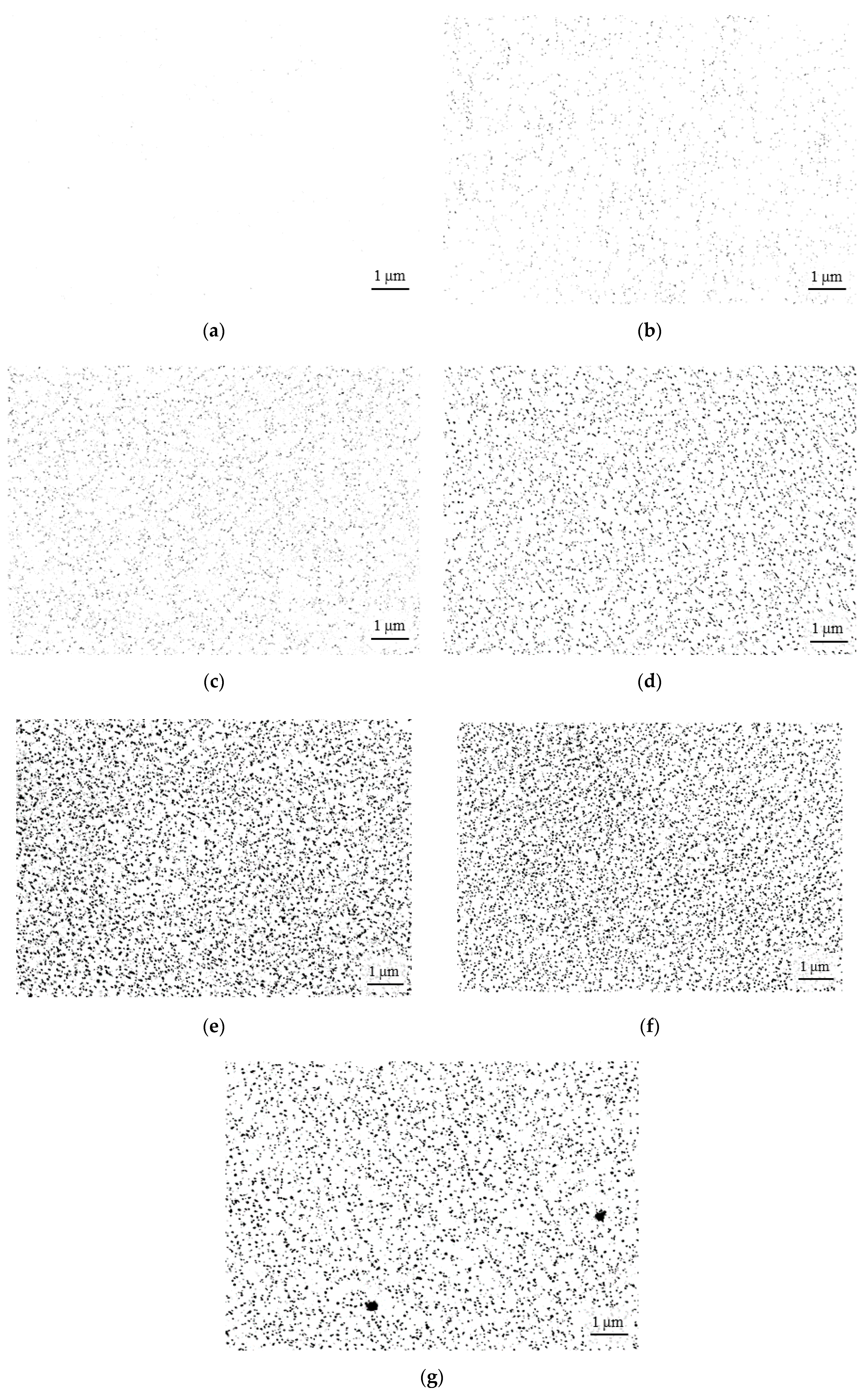
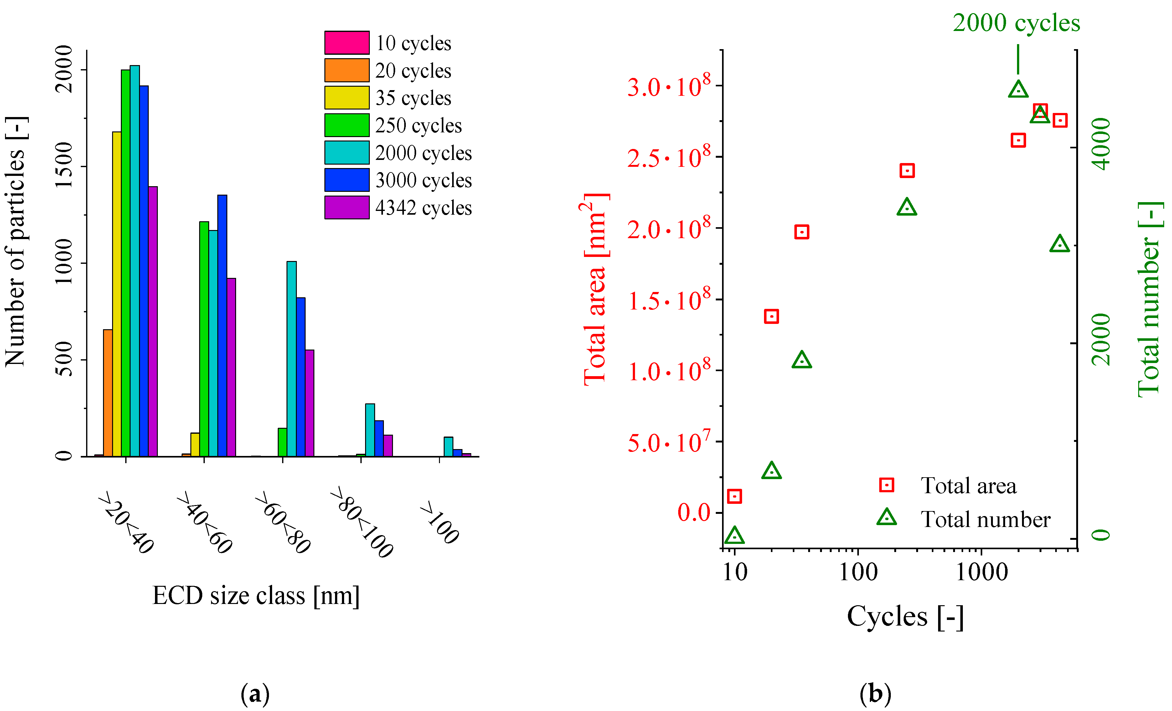
3.4. Thermomechanically Triggered Precipitation in Crofer®22 H

As outlined in Section 3.1, Crofer®22 H strengthens by about 25% over the first 35 cycles (Figure 3a,b), where it constitutes a peak in stress range and consecutively softens slightly by appr. 5% until the end of the initial phase. The underlying microstructural mechanisms are complex.
First, the generation of dislocations by cyclic plasticization within the first 10 cycles (cf. Figure 7a or Figure 8a: Almost no precipitates detectable yet) leads to strain hardening (observable from widening of the hysteresis loop and an increase in stress range, cf. Figure 3d), which by itself would be non-permanent. Second, the induced dislocations accelerate nucleation of small, intergranular Laves phase particles, which become clearly visible in between 10 and 20 cycles (Figure 7a,b). This further increases the stress response (Figure 3d). Third, the thermomechanically induced precipitates [28,29,30,31,32] pin the dislocations and through this make (at least part of the) dislocation-induced strain hardening quasi permanent. With the applied heating/cooling rate of 10 Ks−1 the first 20 cycles accumulate up to a dwell time of just 200 s (3, 33 min.) at temperatures higher than 600 °C, which is necessary to induce strengthening of Laves phase precipitation in Crofer®22 H in a reasonable time (i.e., hours or less) [28]. In isothermal, isochoric (without cyclic plasticization) precipitation annealing at 650 °C, about 30 min is needed to obtain a comparable number of Laves phase precipitates [39]. Deformation, in this case induced during TMF cycling, thus has a strong accelerating effect on precipitation kinetics. At 35 cycles, the peak stress range (Figure 3a,b) and the maximum area of the hysteresis loop, which correlates to the maximum deformation energy induced within a single cycle, are reached (Figure 3d). In the following, stress response (Figure 3a,b) and area of the hysteresis loop (Figure 3d) start decreasing slowly, while the increase in the number of particles saturates just towards 250 cycles (Figure 7c: 35 cycles, i.e., ~6 min. @ T ≥ 600 °C vs. Figure 7d: 250 cycles, i.e., ~42 min. @ T ≥ 600 °C, cf. Figure 8a).
Exhaustion of Laves phase-forming elements from the alloy matrix and consequently a deceleration of precipitation kinetics are the cause of this phenomenon. Dislocations may be generated in greater number or more rapidly than they can be populated by newly nucleating particles. Recovery then establishes a dynamic balance between generation and annihilation of dislocations in the stable curve region, but on a higher stable stress range level than without precipitation. Enhanced Laves phase volume fraction, which is obtainable by increased levels of the main forming elements W and Nb [23,31,32] and adjusted precipitation kinetics, accessible by adapted Si content [40,41,42], do facilitate establishment of the dynamic balance on an even higher level. Consequently, the drop in the stress response after the peak value could be avoided, the hardening range extended and thus an even higher level of fatigue resistance could be achieved [33]. Aging by particle growth becomes (Figure 7e vs. f, g: 2000 vs. 3000, 4342 cycles, i.e., ~333 vs. 500, 721 min. @ T ≥ 600 °C) observable from the decreasing total number of particles at almost constant total particle area beyond 2000 cycles (Figure 8b).

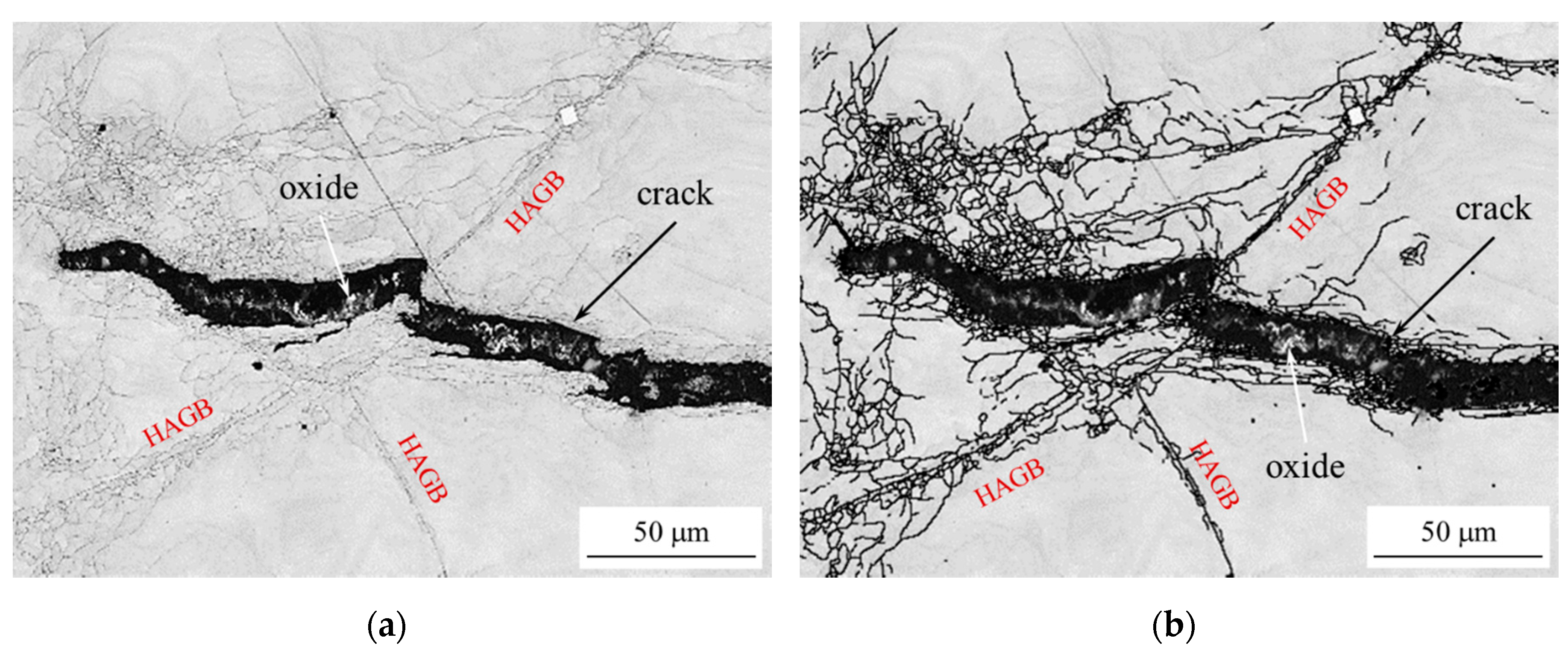
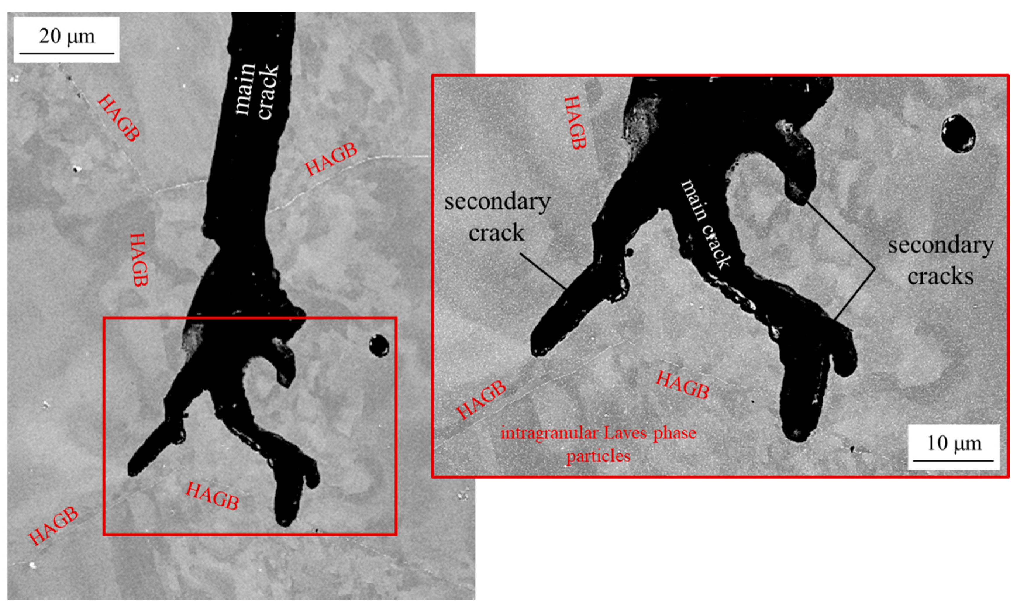
3.5. Damage Initiation and Crack Propagation

Damage, assessed from deviation of the fatigue curve from a linear approximation to the stable curve section, appears at 1961 cycles in P91 (Figure 3a, Table 2). A site of preferential crack initiation and propagation is hard to identify because of the martensite lath degradation, but typically crack branching at triple junctions (Figure 4e) is not encountered. Consequently, P91 exhibits a mixed inter-/intragranular, not the expected fatigue typical, exclusively transgranular [43] crack propagation. The same was encountered in the case of long crack propagation under creep fatigue conditions at 600 °C in X20 steel [44,45], where a similar type of polygonization of the martensite lath microstructure took place because of plastic strain agglomeration in front of crack tips. Based on the results it seems plausible to utilize such pronounced microstructural changes for the assessment of fatigue damage susceptibility of AFM steels. Nevertheless, further detailed examination on the relevance of cycle parameters to polygonization, the relation of the extent of polygonization to macroscopic crack initiation and extension to other AFM steels is necessary for secure application in damage and remaining life assessment. Furthermore, creep strength determination of such pre-fatigued microstructures appears to be imperative.
In Crofer®22 H, damage is induced at 1993 cycles (Figure 3a, Table 2). Crack nucleation and propagation are typically transgranular (Figure 9 and Figure 10). Formation and migration of sub-grain boundaries in the grain interiors is hindered by the intragranular Laves phase precipitates. Polygonization phenomena for this reason are constricted to areas of large plastic distortions, like slender zones along fatigue crack edges (~50–60 µm, cf. Figure 9b) and PFZs, in which dislocation pinning by precipitates is not effective enough along high-angle grain boundaries (Figure 9b). Crack progression is furthermore obstructed by precipitates in front of cracks, which prevent the formation of sharp crack tips (Figure 9 and Figure 10) and in this way contribute to the described decrease of stress range degression per fatigue cycle in comparison to martensitic P91. The higher cyclic hardening potential and increased damage tolerance of Crofer®22 H is analyzed in detail in [46].
Particle-covered high-angle grain boundaries and sub-grain boundaries, condensing from cyclically induced dislocations, in front of and around the edges of cracks as well as within PFZs, often lead to crack branching (Figure 10). This dissipates energy away from the main crack path and constitutes another mechanism causing damage to progress and final failure to appear less rapid in ferritic Crofer®22 H steel.
Enhanced, deformation-induced precipitation, achieved by optimized alloy composition, may potentially lead to a kind of active crack obstruction by particles nucleating in front of propagating crack tips. By this, further increase of fatigue strength may be achievable.

4. Conclusions

The conclusions drawn from this extensive microstructural study of ferritic-martensitic P91 and ferritic, stainless, Laves phase strengthened Crofer®22 H steel under thermomechanical fatigue loading are:
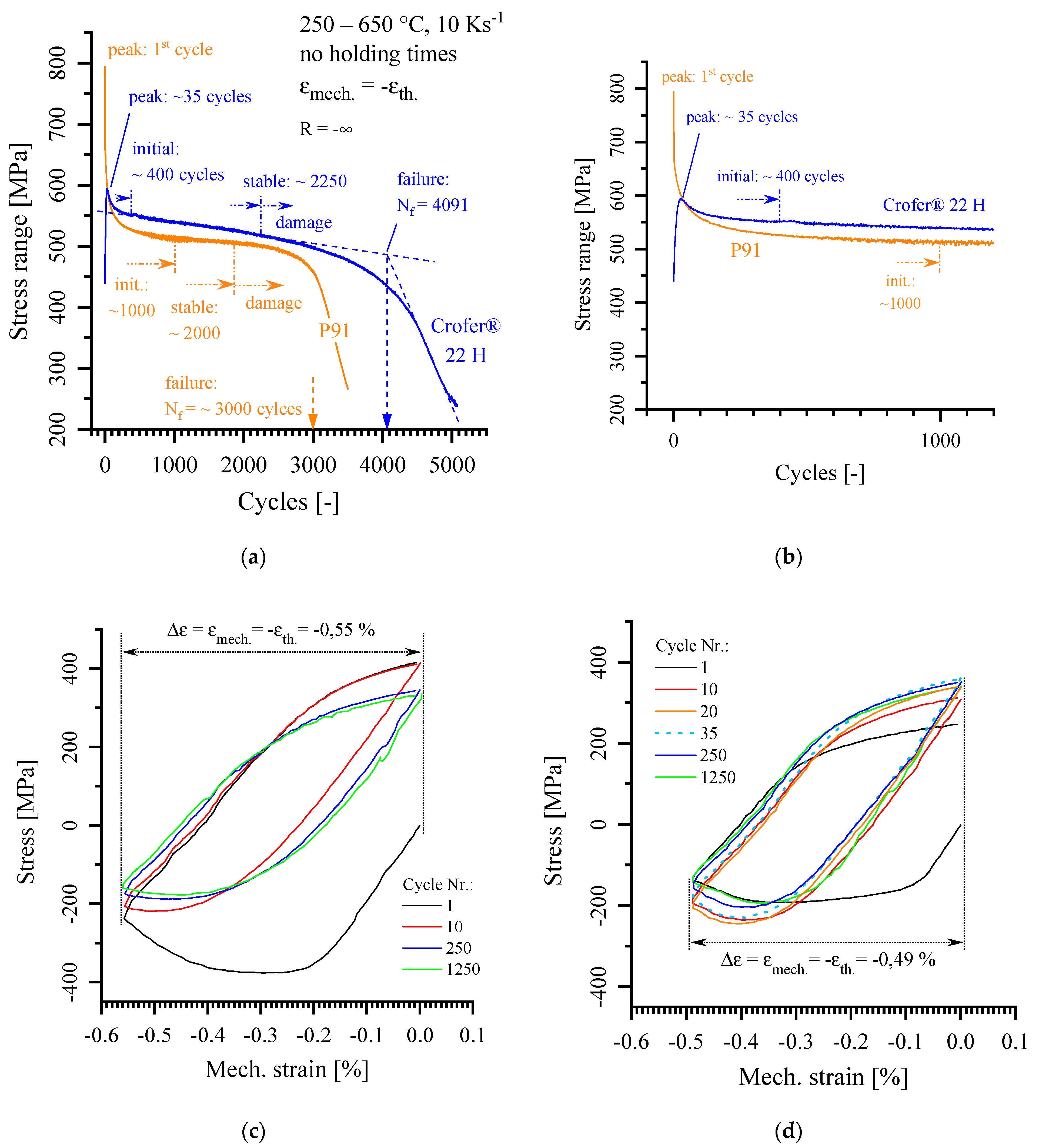
  • The pronounced initial drop in stress response of ferritic-martensitic P91 is associated to recovery of excess dislocations, remaining from martensitic transformation even after tempering.
  • Microstructural instability manifests in transition to the stable stress range phase of the fatigue curve, leads to polygonization of the martensite lath structure and finally results in a refined sub-grain size matching the original martensite lath width after tempering.
  • Polygonization is not associated to stress concentrators like crack tips, crack edges or inclusions, but a result of thermomechanically induced dislocation activity within the entirety of martensite laths.
  • Utilization of the polygonization phenomenon for the assessment of fatigue damage susceptibility and remaining life assessment is plausible, but necessitates further examination on the impact of cycle parameters and the relation of polygonization to macroscopic cracking as well as broadening to other AFM steels.
  • Creep strength of pre-fatigued AFM microstructures shall be revisited.
  • The ferritic, stainless, Laves phase-strengthened Crofer®22 H steel exhibits superior microstructural stability and consequently TMF lifetime, based on:
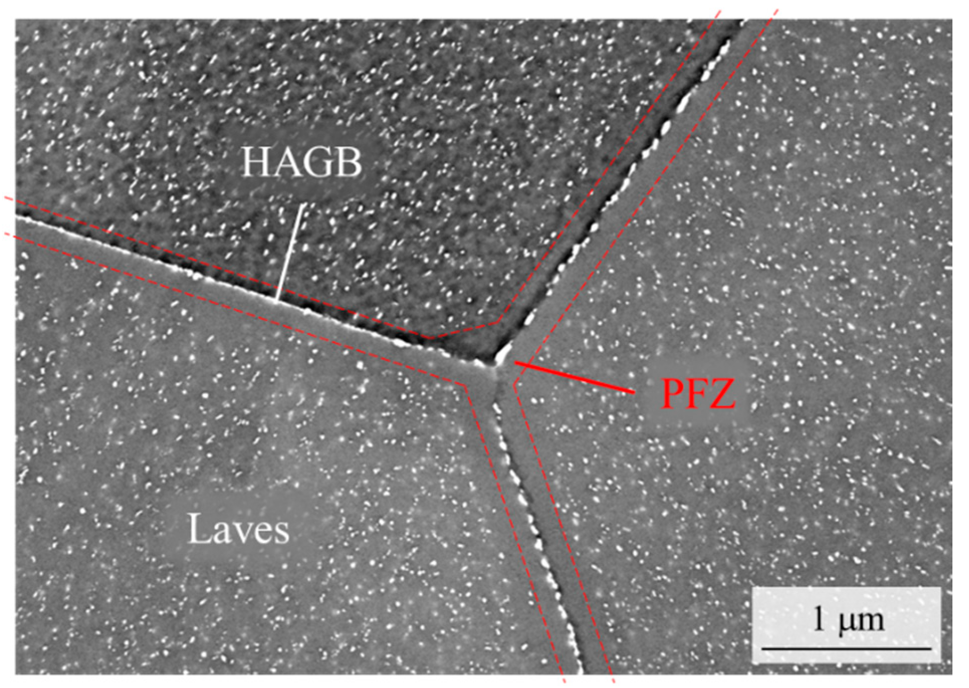
    • Crack obstruction by thermomechanically triggered precipitation of small Laves phase particles, stabilization of the HAGB structure and restriction of polygonization to strongly deformed areas (cracks tips and edges, PFZs at HAGBs) and
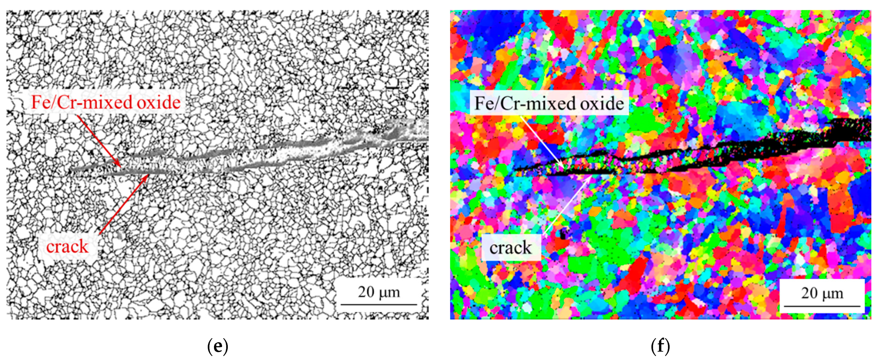
    • crack branching at sub-grain boundaries and active crack obstruction by thermomechanically triggered precipitation of Laves phase particles in front of propagating crack tips are suspected other mechanisms, which cause the encountered decrease in stress range degression per fatigue cycle after crack initiation, but further investigation is necessary to substantiate these postulated mechanisms.
  • The alloying system offers potential for a further increase in fatigue resistance by enhanced precipitate volume fraction and adjusted precipitation kinetics.

Author Contributions

Conceptualization, B.K.; methodology, B.K.; validation, B.K., J.L.B. and T.F.; formal analysis, B.K., J.L.B. and T.F.; investigation, B.K., J.L.B. and T.F.; resources, B.K.; data curation, B.K., J.L.B. and T.F.; writing—original draft preparation, B.K.; writing—review and editing, B.K. and T.F.; visualization, B.K. and J.L.B.; supervision, B.K.; project administration, B.K.; funding acquisition, B.K. All authors have read and agreed to the published version of the manuscript.

Funding

This research received no external funding.

Acknowledgments

The authors would like to express their gratitude to B. Werner for mechanical testing, V. Gutzeit and J. Bartsch for metallographic preparation and E. Wessel and D. Grüner for microstructural characterization work.

Conflicts of Interest

The authors declare no conflict of interest.

References

  1. Tomschi, U. Flexible thermische Kraftwerkefür die Energiewende. Elektrotechnik Inf. 2013, 130, 81–86. [Google Scholar] [CrossRef]
  2. Electric Power System Flexibility: Challenges and Opportunities; EPRI Report 3002007374; 2016; p. 11. Available online: https://www.naseo.org/Data/Sites/1/flexibility-white-paper.pdf (accessed on 31 July 2020).
  3. Flexibility Toolbox—Compilation of Measures for the Flexible Operation of Coal-Fired Power Plants; VGB-B-033; VGB Powertech: Essen, Germany, 2018; p. 35. ISBN 978-3-96284-047-1. Available online: https://www.vgb.org/flexibility_toolbox.html?dfid=90943 (accessed on 31 July 2020).
  4. Nagesha, A.; Kannan, R.; Srinivasan, V.S.; Parameswaran, P.; Sandhya, R.; Choudhary, B.K.; Mathew, M.D.; Jayakumar, T.; Rajendra Kumar, E. Thermomechanical Fatigue Behavior of a Reduced Activation Ferritic-Martensitic Steel. Procedia Eng. 2014, 86, 88–94. [Google Scholar] [CrossRef] [Green Version]
  5. Marek, A.; Junak, G.; Okrajni, J. Fatigue life of creep resisting steels under conditions of cyclic mechanical and thermal interactions. Arch. Mater. Sci. Eng. 2009, 40, 37–40. [Google Scholar]
  6. Kannan, R.; Shankar, V.; Sandhya, R.; Mathew, M.D. Comparative Evaluation of the Low Cycle Fatigue Behaviours of P91 and P92 Steels. Procedia Eng. 2013, 55, 149–153. [Google Scholar] [CrossRef] [Green Version]
  7. Suresh, S. Fatigue of Materials, 2nd ed.; Cambridge University Press: Cambridge, UK, 1998. [Google Scholar]
  8. Armas, A.F.; Petersen, C.; Schmitt, R.; Avalos, M.; Alvarez-Armas, I. Mechanical and microstructural behaviour of isothermally and thermally fatigued ferritic/martensitic steels. J. Nucl. Mater. 2002, 307–311, 509–513. [Google Scholar] [CrossRef]
  9. Giroux, P.F.; Dalle, F.; Sauzay, M.; Caës, C.; Fournier, B.; Morgeneyer, T.; Gourgues-Lorenzon, A.F. Influence of strain rate on P92 microstructural stability during fatigue tests at high temperature. Procedia Eng. 2010, 2, 2141–2150. [Google Scholar] [CrossRef]
  10. Kannan, R.; Srinivasan, V.S.; Valsan, M.; Bhanu Sankara Rao, K. High temperature low cycle fatigue behaviour of P92 tungsten added 9Cr steel. Trans. Indian Inst. Met. 2010, 63, 571–574. [Google Scholar] [CrossRef]
  11. Nagesha, A.; Valsan, M.; Kannan, R.; Bhanu, S.R.K.; Mannan, S.L. Influence of temperature on the low cycle fatigue behaviour of amodified 9Cr–1Mo ferritic steel. Int. J. Fatigue 2002, 24, 1285. [Google Scholar] [CrossRef]
  12. Shankar, V.; Bauer, V.; Sandhya, R.; Mathew, M.D.; Christ, H.-J. Low cycle fatigue and thermo-mechanical fatigue behavior of modified 9Cr–1Mo ferritic steel at elevated temperatures. J. Nucl. Mater. 2012, 420, 23–30. [Google Scholar] [CrossRef]
  13. Nagesha, A.; Kannan, R.; Sandhya, R.; Mathew, M.D.; Bhanu, S.R.K.; Singh, V. Thermomechanical Fatigue Behavior of a Modified 9Cr-1Mo Ferritic-Martensitic Steel. Procedia Eng. 2013, 55, 199–203. [Google Scholar] [CrossRef] [Green Version]
  14. Choudhary, B.K.; Bhanu, S.R.K.; Mannan, S.L. High temperature low cycle fatigue properties of a thick-section 9wt.%Cr-1wt.%Mo ferritic steel forging. Mater. Sci. Eng. A 1991, 148, 267–278. [Google Scholar] [CrossRef]
  15. Kuhn, B.; Talik, M.; Lopez Barrilao, J.; Singheiser, L. Microstructure stability of ferritic-martensitic, austenitic and fully ferritic steels under fluctuating loading conditions. In Proceedings of the 1st 123 HiMat Conference on Advanced High-Temperature Materials Technology for Sustainable and Reliable Power Engineering (123HiMAT-2015), Sapporo, Japan, 29 June–3 July 2015; Murata, Y., Ohmori, T., Igarashi, M., Kimura, K., Takeyama, M., Eds.; The 123rd Committee of Japan Society for the Promotion of Science, IAL: Tokyo, Japan, 2015; pp. 94–97. ISBN 978-4-9908874-0-7. [Google Scholar]
  16. Kuhn, B.; Lopez Barrilao, J.; Fischer, T. “Reactive” Microstructure: The Key to Cost Effective, Fatigue Resistant High Temperature Structural Materials. In Proceedings of EPRI’s 9th International Conference on Advances in Materials Technology for Fossil Power Plants and the 2nd International 123HiMAT Conference on High-Temperature Materials, Nagasaki, Japan, 21–25 October 2019; Shingledecker, J., Takeyama, M., Eds.; ASM International: Russell Township, OH, USA, 2019; pp. 1–10. [Google Scholar]
  17. Abe, F. Precipitate design for creep strengthening of 9% Cr tempered martensitic steel for ultra-supercritical power plants. Sci. Technol. Adv. Mater. 2008, 9, 1–15. [Google Scholar] [CrossRef] [PubMed]
  18. Cerjak, H.; Hofer, P.; Schaffernak, B. The Influence of Advanced of Microstructural Aspects on the Service Behaviour of Advanced Power Plant Steels. ISIJ Int. 1999, 39, 874–888. [Google Scholar] [CrossRef]
  19. Ennis, P.J.; Zielinska-Lipiec, A.; Wachter, O.; Czyrska-Filemonowicz, A. Microstructural stability and creep rupture strength of the martensitic steel P92 for advanced power plant. Acta Mater. 1997, 45, 4901–4907. [Google Scholar] [CrossRef]
  20. Crofer®22 H–Material Data Sheet. Available online: https://www.vdm-metals.com/fileadmin/user_upload/Downloads/Data_Sheets/Data_Sheet_VDM_Crofer_22_H.pdf (accessed on 16 March 2020).
  21. Danzer, M.; Wetzel, F.-J.; Yan, X.; Hoefler, T.; Kuhn, B.; Stoermer, A.O.; Finkenwirth, O. Fuel Cell Stack. WO 2004/021488, 11 March 2004. [Google Scholar]
  22. Schiller, G.; Franco, T.; Henne, R.; Lang, M.; Szabo, P.; Finkenwirth, O.; Kuhn, B.; Wetzel, F.-J. Development of Thin-Film SOFC for Stationary and Mobile Application by Using Plasma Deposition Technology; The Electrochemical Society: Pennington, NJ, USA, 2003; pp. 1051–1058. [Google Scholar] [CrossRef]
  23. Froitzheim, J.; Meier, G.H.; Niewolak, L.; Ennis, P.J.; Hattendorf, H.; Singheiser, L. Development of high strength ferritic steel for interconnect application in SOFCs. J. Power Sources 2008, 178, 163–173. [Google Scholar] [CrossRef]
  24. Hsiao, Z.W.; Kuhn, B.; Chen, D.; Singheiser, L.; Kuo, J.C.; Lin, D.Y. Characterization of Laves phase in Crofer 22 H stainless steel. Micron 2015, 74, 59–64. [Google Scholar] [CrossRef] [PubMed]
  25. Beck, T.; Kuhn, B.; Eckardt, T.; Singheiser, L. Microstructure, Creep and Thermomechanical Fatigue of Novel Solid Solution and Laves Phase Strengthened Cr2O3 and Al2O3 Forming Ferrites for Car Engine Exhaust and Heat Exchanger Systems. Trans. Indian Inst. Met. 2016, 69, 379–385. [Google Scholar] [CrossRef]
  26. Kuhn, B.; Jimenez, C.A.; Niewolak, L.; Hüttel, T.; Beck, T.; Hattendorf, H.; Singheiser, L.; Quadakkers, W.J. Effect of Laves phase strengthening on the mechanical properties of high Cr ferritic steels for solid oxide fuel cell interconnect application. Mater. Sci. Eng. A 2011, 528, 5888–5899. [Google Scholar] [CrossRef]
  27. Kuhn, B.; Talik, M. HiperFer—High Performance Ferritic Steels. In Proceedings of the 10th Liége Conference on Materials for Advanced Power Engineering, Liége, Belgium, 14–17 September 2014; pp. 264–273. [Google Scholar]
  28. Hsiao, Z.W.; Kuhn, B.; Yang, S.M.; Yang, L.C.; Huang, S.Y.; Singheiser, L.; Kuo, J.C.; Lin, D.Y. The Influence of Deformation on the Precipitation Behavior of a Ferritic Stainless Steel. In Proceedings of the 10th Liége Conference on Materials for Advanced Power Engineering, Liége, Belgium, 14–17 September 2014; Lecomte-Beckers, J., Dedry, O., Oakey, J., Kuhn, B., Eds.; pp. 349–358. [Google Scholar]
  29. Pöpperlová, J.; Fan, X.; Kuhn, B.; Bleck, W.; Krupp, U. Impact of Tungsten on Thermomechanically Induced Precipitation of Laves Phase in High Performance Ferritic (HiperFer) Stainless Steels. Appl. Sci. 2020, 10, 4472. [Google Scholar] [CrossRef]
  30. Fan, X.; Kuhn, B.; Pöpperlová, J.; Bleck, W.; Krupp, U. Thermomechanically Induced Precipitation in High Performance Ferritic (HiperFer) Stainless Steels. Appl. Sci. 2020, 10, 5713. [Google Scholar] [CrossRef]
  31. Fan, X.; Kuhn, B.; Pöpperlová, J.; Bleck, W.; Krupp, U. Compositional optimization of High performance Ferritic (HiperFer) steels—Effect of niobium and tungsten content. Metals 2020, 10, in preparation. [Google Scholar]
  32. Kuhn, B.; Talik, M.; Niewolak, L.M.; Zurek, J.; Hattendorf, H.; Ennis, P.J. Development of high chromium ferritic steels strengthened by intermetallic phases. Mater. Sci. Eng. A 2014, 594, 372–380. [Google Scholar] [CrossRef]
  33. Kuhn, B.; Talik, M.; Fischer, T.; Fan, X.; Yamamoto, Y.; Lopez Barrilao, J. Science and Technology of High Performance Ferritic (HiperFer) Stainless Steels. Metals 2020, 10, 463. [Google Scholar] [CrossRef] [Green Version]
  34. Lopez Barrilao, J.; Kuhn, B.; Wessel, E. Microstructure evolution and dislocation behaviour in high chromium, fully ferritic steels strengthened by intermetallic Laves phases. Micron 2018, 108, 11–18. [Google Scholar] [CrossRef] [PubMed]
  35. Hähner, P.; Affeldt, E.; Beck, T.; Klingelhöffer, H. Validated Code of Practice for Strain Controlled Thermomechanical Fatigue Testing. 2006. Available online: https://www.researchgate.net/profile/Peter_Haehner/publication/265152601_Validated_Code-of-Practice_for_Strain-Controlled_Thermo-Mechanical_Fatigue_Testing/links/5447bd0f0cf2f14fb8123686.pdf (accessed on 4 March 2020).
  36. Lopez, J.B.; Kuhn, B.; Wessel, E.; Talík, M. Microstructure of intermetallic particle strengthened high-chromium fully ferritic steels. Mater. Sci. Technol. 2017, 33, 1056–1064. [Google Scholar] [CrossRef]
  37. Schneider, C.A.; Rasband, W.S.; Eliceiri, K.W. NIH Image to ImageJ: 25 years of image analysis. Nat. Methods 2012, 9, 671–675. [Google Scholar] [CrossRef]
  38. Lopez, J.B.; Kuhn, B.; Wessel, E. Identification, size classification and evolution of Laves phase precipitates in high chromium, fully ferritic steels. Micron 2017, 101, 221–231. [Google Scholar] [CrossRef]
  39. Kuhn, B.; Talik, M.; Lopez, J.B.; Singheiser, L.; Yamamoto, Y. Development Status of High Performance Ferritic (HiperFer) Steels. In Proceedings of the 8th International Conference on Advances in Materials Technology for Fossil Power Plants, Albufeira, Algarve, Portugal, 11–14 October 2016; pp. 1018–1026, ISBN 13-978-1-62708-131-3. [Google Scholar]
  40. Hosoi, Y.; Wade, N.; Kunimitsu, S.; Urita, T. Precipitation behavior of laves phase and its effect on toughness of 9Cr-2Mo Ferritic-martensitic steel. J. Nucl. Mater. 1986, 141–143, 461–467. [Google Scholar] [CrossRef]
  41. Hättestrand, M.; Schwind, M.; Andrén, H.-O. Microanalysis of two creep resistant 9–12% chromium steels. Mater. Sci. Eng. A 1998, 250, 27–36. [Google Scholar] [CrossRef]
  42. Lundin, L.M. Direct Measurement of Carbon Solubility in the intermetallic (Fe,Cr)2(Mo,W) Laves Phase using Atom-Probe Field-Ion Microscopy. Scr. Mater. 1996, 34, 741–747. [Google Scholar] [CrossRef]
  43. Holdsworth, S.R. Creep-fatigue interaction in steam power plant materials. In Proceedings of the 10th Liége Conference on Materials for Advanced Power Engineering, Liége, Belgium, 14–17 September 2014; Lecomte-Beckers, J., Dedry, O., Oakey, J., Kuhn, B., Eds.; Forschungszentrums: Jülich, Gemany, 2014; pp. 349–358. Available online: https://juser.fz-juelich.de/record/185531/files/FZJ-2014-06958.pdf (accessed on 10 September 2020).
  44. Fischer, T.; Kuhn, B. Frequency and hold time influence on crack growth behavior of a 9–12% Cr ferritic martensitic steel at temperatures from 300 °C to 600 °C in air. Int. J. Fatigue 2018, 112, 165–172. [Google Scholar] [CrossRef]
  45. Fischer, T. Mechanismen des Hochtemperaturrisswachstums in Einem Ferritischen Stahl an Luft und in Wasserdampf; Forschungszentrum Juelich GmbH: Jülich, Germany, 2018; Available online: http://hdl.handle.net/2128/18897 (accessed on 10 September 2020).
  46. Blinn, B.; Görzen, D.; Fischer, T.; Kuhn, B.; Beck, T. Analysis of the thermomechanical fatigue behavior of fully ferritic high chromium steel Crofer®22 H with cyclic indentation testing. Appl. Sci. 2020, 10, in preparation. [Google Scholar]
Figure 1. Scanning electron microscopy (SEM) micrograph of ferritic-martensitic grade P91 steel (1050 °C/0.5 h/AC + 750 °C/1 h/AC).
Applsci 10 06338 g001
Figure 2. SEM micrograph of precipitated ferritic, stainless Crofer®22 H steel (taken after 2000 thermomechanical fatigue (TMF) cycles, cf. Section 3).
Applsci 10 06338 g002
Figure 3. Typical thermomechanical fatigue curves (a) detail (b) and hysteresis loops of ferritic-martensitic (c) and ferritic Crofer®22 H steel (d).
Applsci 10 06338 g003
Figure 4. Binarized images (ae) from post-processed electron backscatter diffraction band contrast images (misorientation angle used to define fatigue induced sub-grain boundaries: >3°, step size: 0.2191 μm) for the quantitative analysis of martensite lath degradation and complete polygonization of ferritic-martensitic grade 91 steel after 0 (a), 10 (b), 250 (c), 1250 (d) and 3500 (e) TMF cycles. (f): Sub-grain orientation added to (e).
Applsci 10 06338 g04aApplsci 10 06338 g04b
Figure 5. Evolution of martensite lath aspect ratio in P91 with an increasing number of TMF cycles.
Applsci 10 06338 g005
Figure 6. Electron backscatter diffraction (EBSD) image (band contrast image, grain boundaries added) of the as-received state (a) of and grain size evolution (b) in ferritic Crofer®22 H.
Applsci 10 06338 g006
Figure 7. Scanning electron micrographs (post-processed, binarized and inverted for better particle visibility) of intragranular Laves phase precipitate evolution in ferritic Crofer®22 H steel during TMF cycling: 10 (a), 20 (b), 35 (c), 250 (d), 2000 (e), 3000 (f) and after failure at 4342 cycles (g).
Applsci 10 06338 g007
Figure 8. Evolution of Laves phase particle population in ferritic Crofer®22 H steel during TMF cycling: Size classification by equivalent circle diameter (ECD) (a) total particle area and number (b).
Applsci 10 06338 g008
Figure 9. Limited sub-grain formation in close vicinity of a crack tip in ferritic Crofer®22 H after TMF failure: SEM image (a) and EBSD band contrast image with fatigue-induced sub-grain boundaries (misorientation definition angle: >3°, step size: 0.438 μm) added (b). HAGB denotes pre-existing high angle grain boundaries.
Applsci 10 06338 g009
Figure 10. Crack branching at deformation induced sub-grain boundaries in Crofer®22 H after TMF failure (SEM micrograph).
Applsci 10 06338 g010
Table 1. Chemical composition (wt %) of the experimental materials.
Batch-ID:CNCrMnSiNbWVAlNiMoLaTi
P910.10.0518.10.46-0.07-0.180.030.330.92--
Crofer®22 H<0.01<0.0122.930.430.210.511.94----0.080.07
Table 2. Half-life stress range, damage initiation Nd, technical TMF lifetime Nf and damage ranges (250−650 °C, εmech. = εth, Rε, mech = −∞, 10 Ks−1, no holding times at Tmin. and Tmax.).σ.
Material:σ@Nf/2
[MPa}
σmean@Nf/2
[MPa}
Nd
[-]
Def. Energy
@Nd
[MJm−3]
Nf
[-]
Def. Energy
@Nf
[MJm−3]
Damage Range
[%]
P915097519612225.129723315.834.0
Crofer®22 H5229119932410.540914177.845.2

