Tool Wear and Material Removal Predictions in Micro-EDM Drilling: Advantages of Data-Driven Approaches


Abstract
:1. Introduction
2. Materials and Methods
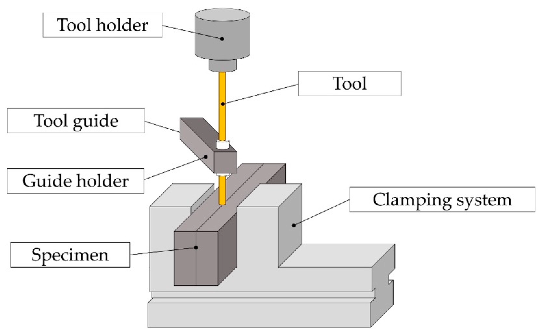
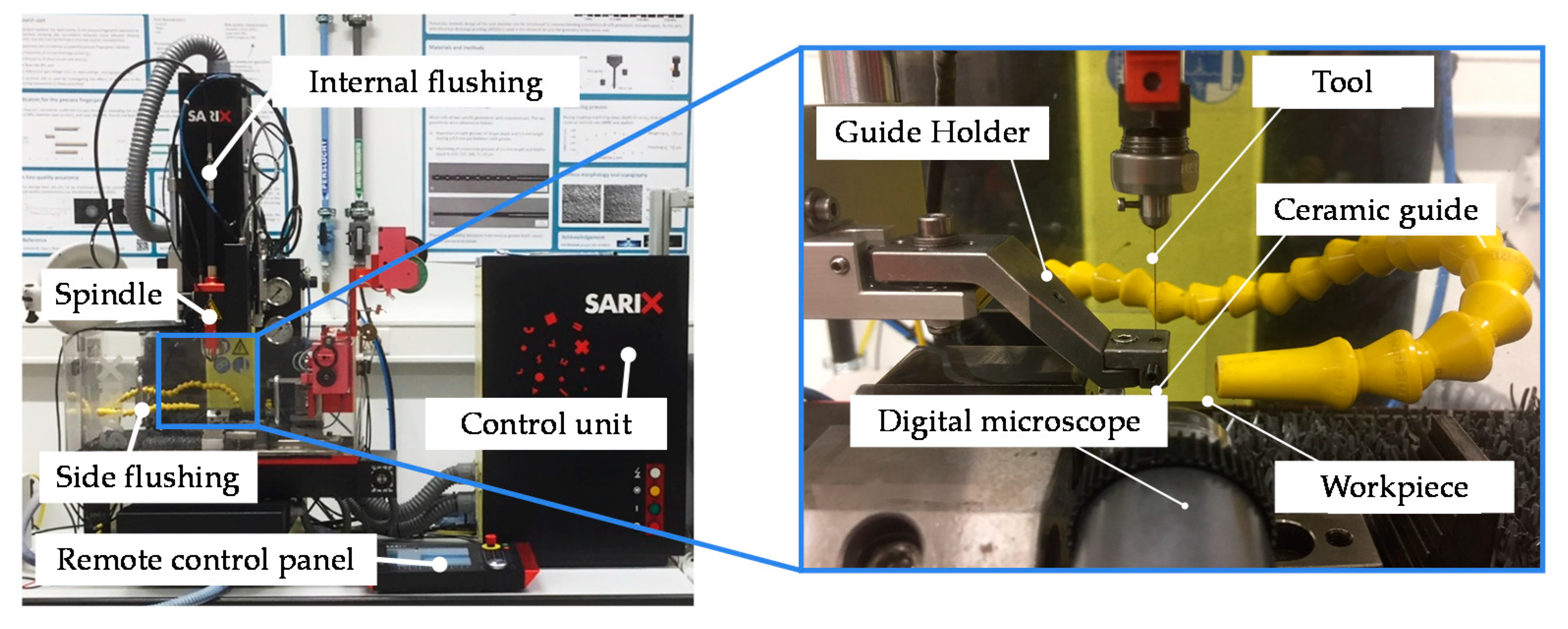
2.1. Experimental Setup
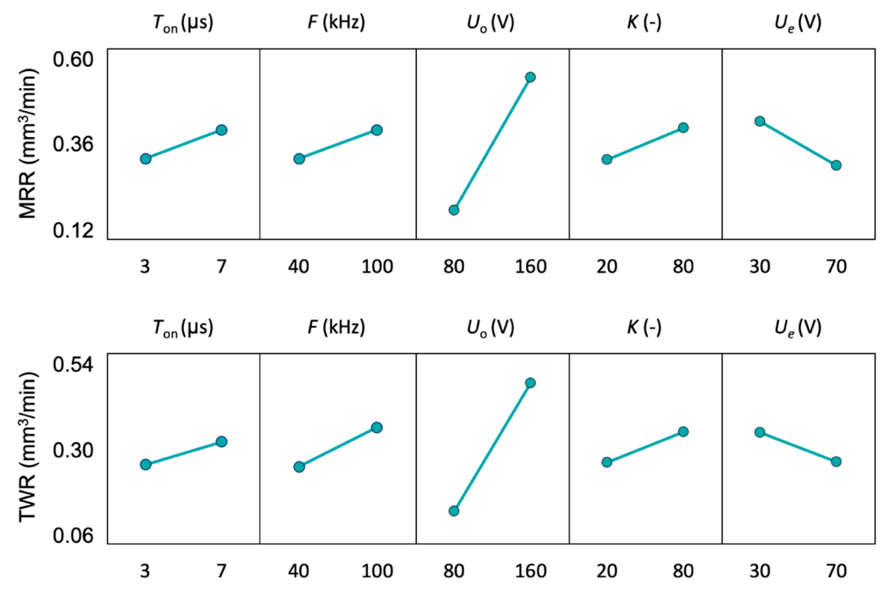
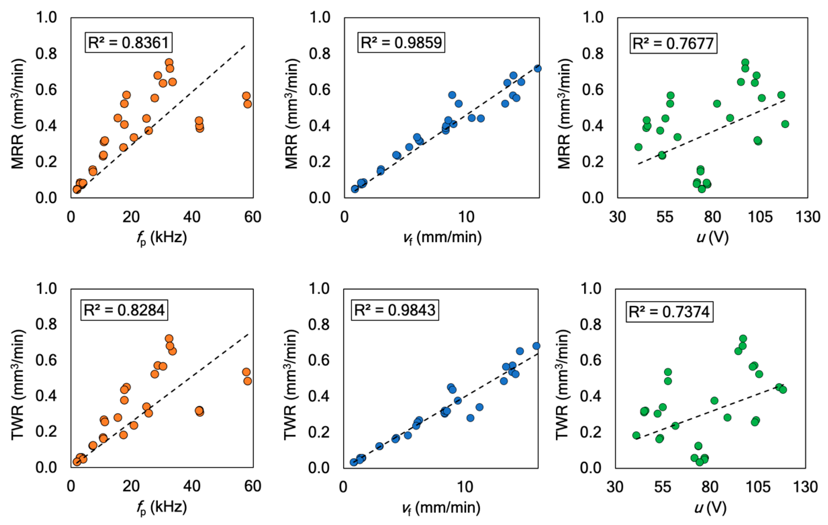
2.2. Data Collection
3. Predictive Models
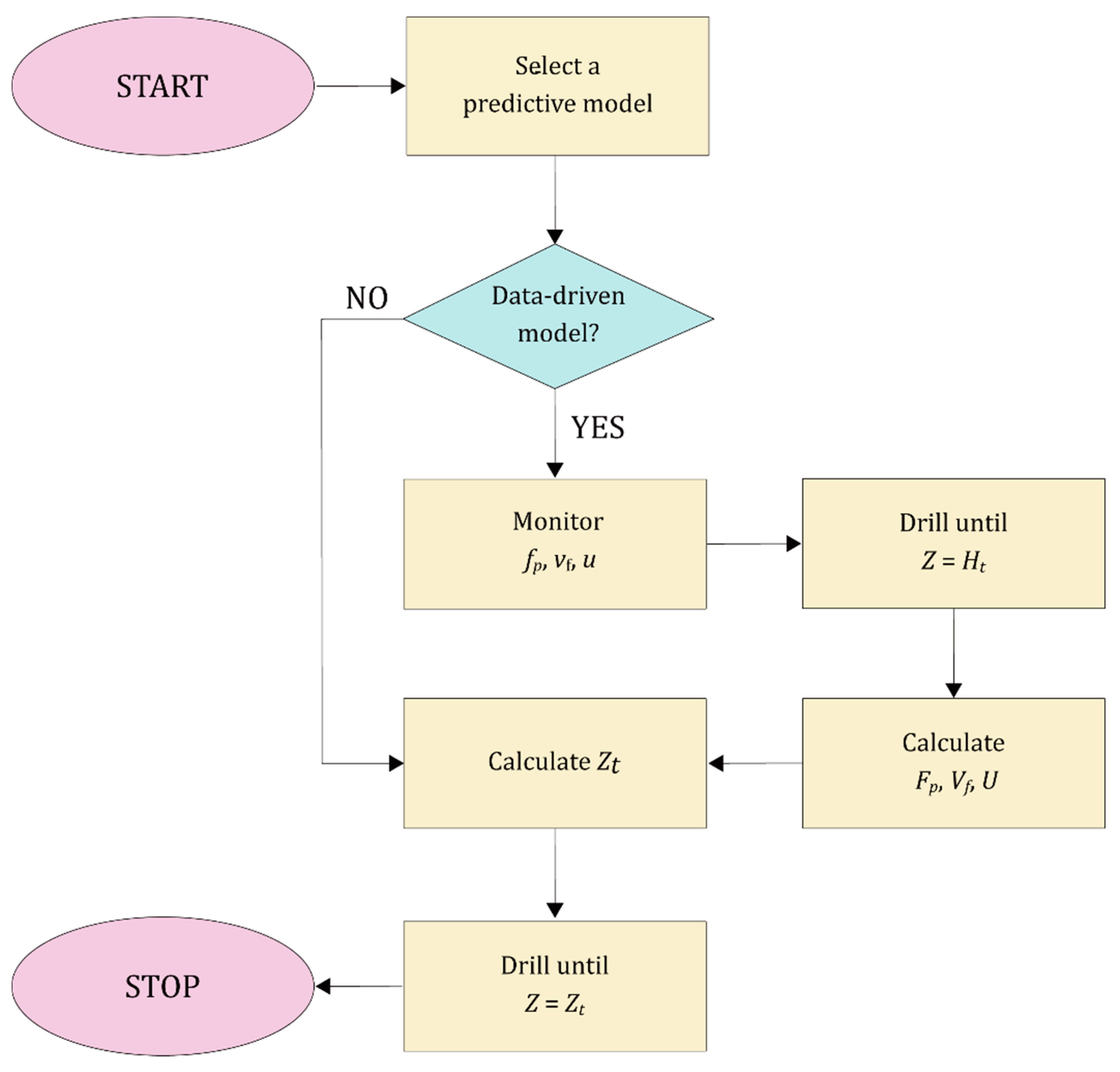
4. In-Process Tool Wear Prediction and Hole Depth Control
5. Results and Discussion
5.1. Predictive Models
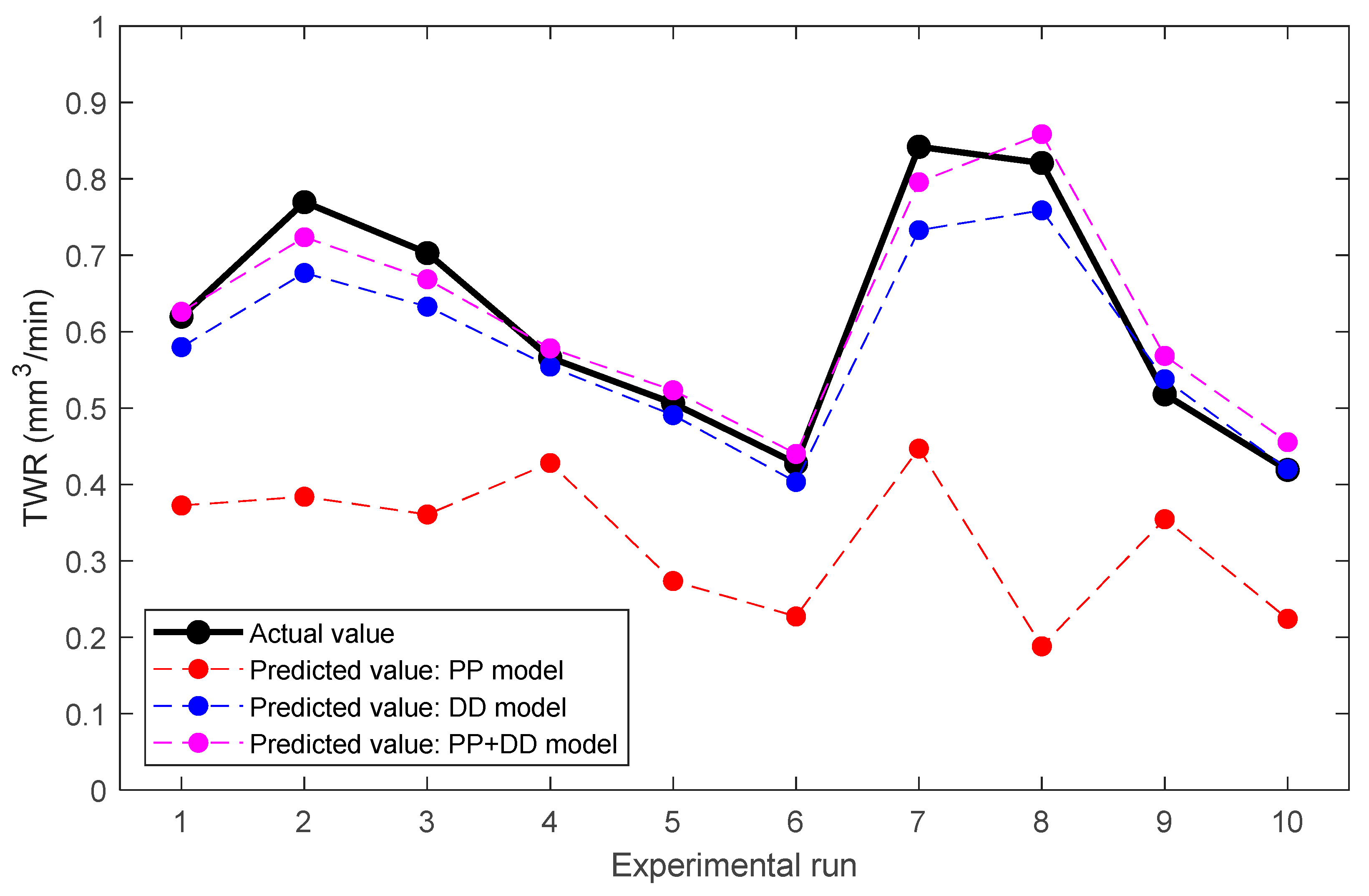
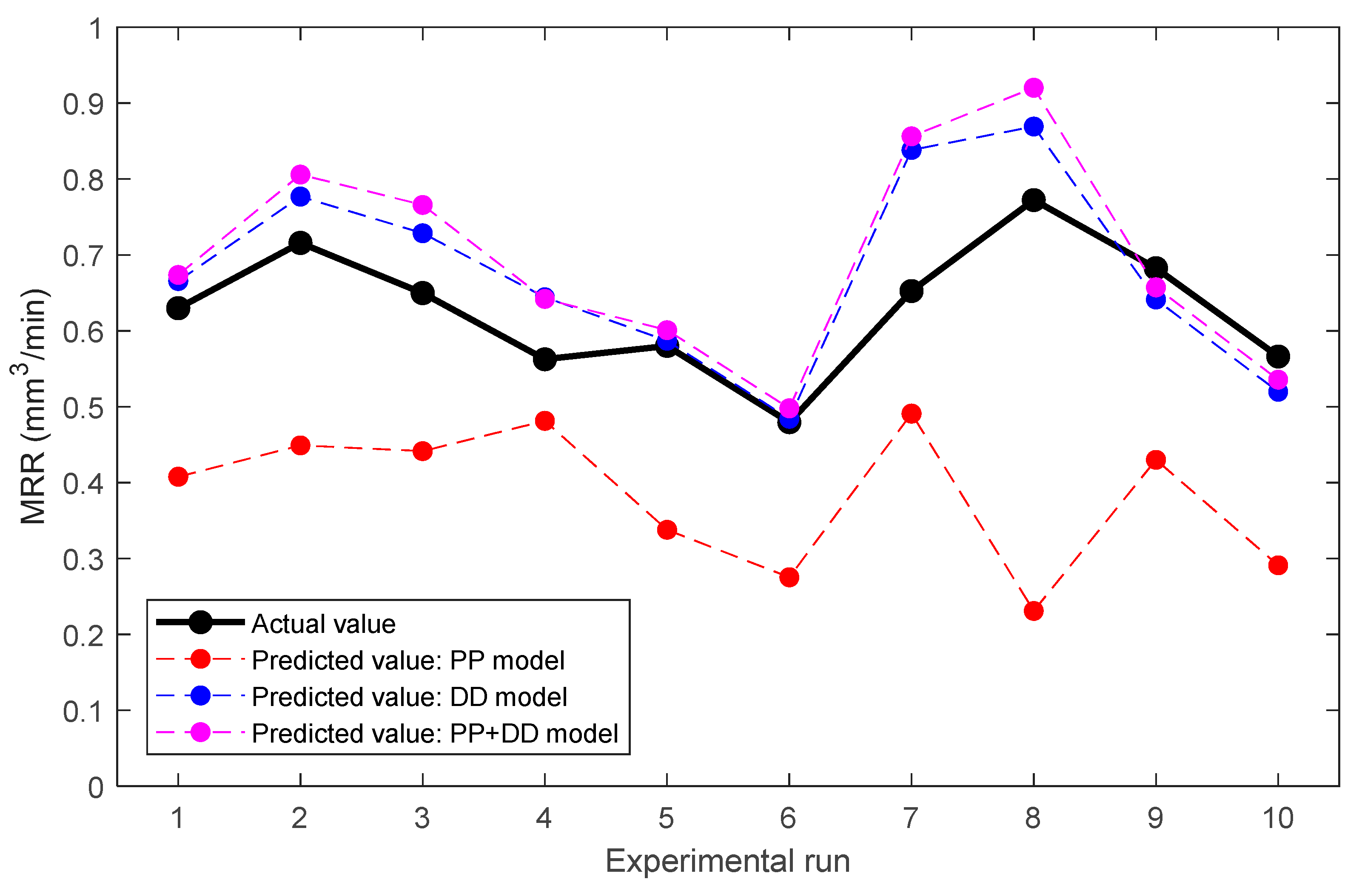
5.2. Prediction Accuracy
5.3. Real-Time Wear Prediction and Hole Depth Control
6. Conclusions
Author Contributions
Funding
Conflicts of Interest
References
- Biscaia, R.V.B.; Ribas, M.T.; Júnior, A.B. Effects of processing parameters on the micro-drilling through fast hole electroerosion and laser trepanning in Inconel 718. Int. J. Adv. Manuf. Technol. 2020, 106, 31–45. [Google Scholar] [CrossRef]
- Kumar, K.; Singh, V.; Katyal, P.; Sharma, N. EDM μ-drilling in Ti-6Al-7Nb: Experimental investigation and optimization using NSGA-II. Int. J. Adv. Manuf. Technol. 2019, 104, 2727–2738. [Google Scholar] [CrossRef]
- Mufti, N.A.; Rafaqat, M.; Ahmed, N.; Saleem, M.Q.; Hussain, A.; Al-Ahamri, A.M. Improving the performance of EDM through relief-angled tool designs. Appl. Sci. 2020, 10, 2432. [Google Scholar] [CrossRef] [Green Version]
- Tong, H.; Li, Y.; Zhang, L.; Li, B. Mechanism design and process control of micro EDM for drilling spray holes of diesel injector nozzles. Precis. Eng. 2013, 37, 213–221. [Google Scholar] [CrossRef]
- Li, Z.Y.; Wei, X.T.; Guo, Y.B.; Sealy, M.P. State-Of-Art, Challenges, and Outlook on Manufacturing of Cooling Holes for Turbine Blades. Mach. Sci. Technol. 2015, 19, 361–399. [Google Scholar] [CrossRef]
- D’Urso, G.; Maccarini, G.; Ravasio, C. Process performance of micro-EDM drilling of stainless steel. Int. J. Adv. Manuf. Technol. 2014, 72, 1287–1298. [Google Scholar] [CrossRef]
- Kuppan, P.; Narayanan, S.; Rajadurai, A.; Adithan, M. Effect of EDM parameters on hole quality characteristics in deep hole drilling of Inconel 718 superalloy. Int. J. Manuf. Res. 2015, 10, 45. [Google Scholar] [CrossRef]
- Skoczypiec, S.; Machno, M.; Bizoń, W. The capabilities of electrodischarge microdrilling of high aspect ratio holes in ceramic materials. Manag. Prod. Eng. Rev. 2015, 6, 61–69. [Google Scholar] [CrossRef] [Green Version]
- Puertas, I.; Luis, C.J.; Álvarez, L. Analysis of the influence of EDM parameters on surface quality, MRR and EW of WC-Co. J. Mater. Process. Technol. 2004, 153, 1026–1032. [Google Scholar] [CrossRef]
- Mohan, B.; Rajadurai, A.; Satyanarayana, K.G. Electric discharge machining of Al-SiC metal matrix composites using rotary tube electrode. J. Mater. Process. Technol. 2004, 153, 978–985. [Google Scholar] [CrossRef]
- Suganthi, X.H.; Natarajan, U.; Sathiyamurthy, S.; Chidambaram, K. Prediction of quality responses in micro-EDM process using an adaptive neuro-fuzzy inference system (ANFIS) model. Int. J. Adv. Manuf. Technol. 2013, 68, 339–347. [Google Scholar] [CrossRef]
- Barenji, R.V.; Pourasl, H.H.; Khojastehnezhad, V.M. Electrical discharge machining of the AISI D6 tool steel: Prediction and modeling of the material removal rate and tool wear ratio. Precis. Eng. 2016, 45, 435–444. [Google Scholar] [CrossRef]
- Gao, Q. Impact of electrode length on EDM inclined hole drilling process. Int. J. Adv. Manuf. Technol. 2018, 94, 1171–1175. [Google Scholar] [CrossRef]
- Li, Z.; Bai, J. Impulse discharge method to investigate the influence of gap width on discharge characteristics in micro-EDM. Int. J. Adv. Manuf. Technol. 2017, 90, 1769–1777. [Google Scholar] [CrossRef]
- Bissacco, G.; Hansen, H.; Tristo, G.; Valentincic, J. Feasibility of wear compensation in micro EDM milling based on discharge counting and discharge population characterization. CIRP Ann. Manuf. Technol. 2011, 60, 231–234. [Google Scholar] [CrossRef]
- D’Urso, G.; Ravasio, C. The effects of electrode size and discharged power on micro-electro-discharge machining drilling of stainless steel. Adv. Mech. Eng. 2016, 8, 1–12. [Google Scholar] [CrossRef] [Green Version]
- Bellotti, M.; Qian, J.; Reynaerts, D. Process Fingerprint in Micro-EDM Drilling. Micromachines 2019, 10, 240. [Google Scholar] [CrossRef] [Green Version]
- Mohanty, S.; Kumar, V.; Kumar Das, A.; Dixit, A.R. Surface modification of Ti-alloy by micro-electrical discharge process using tungsten disulphide powder suspension. J. Manuf. Process. 2019, 37, 28–41. [Google Scholar] [CrossRef]
- Qudeiri, J.E.A.; Mourad, A.I.; Ziout, A.; Abidi, M.H.; Elkaseer, A. Electric discharge machining of titanium and its alloys: Review. Int. J. Adv. Manuf. Technol. 2018, 96, 1319–1339. [Google Scholar] [CrossRef]
- Xia, W.; Zhang, Y.; Chen, M.; Zhao, W. Study on Gap Phenomena Before and After the Breakout Event of Fast Electrical Discharge Machining Drilling. J. Manuf. Sci. Eng. 2020, 142. [Google Scholar] [CrossRef]
- Bellotti, M.; Qian, J.; Reynaerts, D. Breakthrough phenomena in drilling micro holes by EDM. Int. J. Mach. Tools Manuf. 2019, 146. [Google Scholar] [CrossRef]
- Moses, M.D.; Jahan, M.P. Micro-EDM machinability of difficult-to-cut Ti-6Al-4V against soft brass. Int. J. Adv. Manuf. Technol. 2015, 81, 1345–1361. [Google Scholar] [CrossRef]
- D’Urso, G.; Merla, C. Workpiece and electrode influence on micro-EDM drilling performance. Precis. Eng. 2014, 38, 903–914. [Google Scholar] [CrossRef]
- Bellotti, M.; Qian, J.; Reynaerts, D. Enhancement of the micro-EDM process for drilling through-holes. Procedia CIRP 2018, 68, 610–615. [Google Scholar] [CrossRef]
- Karthikeyan, G.; Ramkumar, J.; Dhamodaran, S.; Aravindan, S. Micro electric discharge milling process performance: An experimental investigation. Int. J. Mach. Tools Manuf. 2010, 50, 718–727. [Google Scholar] [CrossRef]
- Pham, D.T.; Ivanov, A.; Bigot, S.; Popov, K.; Dimov, S. An investigation of tube and rod electrode wear in micro EDM drilling. Int. J. Adv. Manuf. Technol. 2007, 33, 103–109. [Google Scholar] [CrossRef]
- Kar, S.; Patowari, P.K. Electrode wear phenomenon and its compensation in micro electrical discharge milling: A review. Mater. Manuf. Process. 2018, 33, 1491–1517. [Google Scholar] [CrossRef]
- Qudeiri, J.E.A.; Zaiout, A.; Mourad, A.-H.I.; Abidi, M.H.; Elkaseer, A. Principles and Characteristics of Different EDM Processes in Machining Tool and Die Steels. Appl. Sci. 2020, 10, 2082. [Google Scholar] [CrossRef] [Green Version]
- Bellotti, M.; Qian, J.; Reynaerts, D. Self-tuning breakthrough detection for EDM drilling micro holes. J. Manuf. Process. 2020, 57, 630–640. [Google Scholar] [CrossRef]
- Shabgard, M.; Ahmadi, R.; Seyedzavvar, M.; Oliaei, S.N.B. Mathematical and numerical modeling of the effect of input-parameters on the flushing efficiency of plasma channel in EDM process. Int. J. Mach. Tools Manuf. 2013, 65, 79–87. [Google Scholar] [CrossRef]
- Wu, M.; Liu, J.; He, J.; Chen, X.; Guo, Z. Fabrication of surface microstructures by mask electrolyte jet machining. Int. J. Mach. Tools Manuf. 2020, 148, 103471. [Google Scholar] [CrossRef]
- Nadda, R.; Nirala, C.K. Thermal modeling of single discharge in prospect of tool wear compensation in μEDM. Int. J. Adv. Manuf. Technol. 2020, 107, 4573–4595. [Google Scholar] [CrossRef]
- Somashekhar, K.P.; Panda, S.; Mathew, J.; Ramachandran, N. Numerical simulation of micro-EDM model with multi-spark. Int. J. Adv. Manuf. Technol. 2013, 6, 83–90. [Google Scholar] [CrossRef]
- Li, X.; Wei, D.; Li, Q.; Yang, X. Study on effects of electrode material and dielectric medium on arc plasma in electrical discharge machining. Int. J. Adv. Manuf. Technol. 2020, 107, 4403–4413. [Google Scholar] [CrossRef]
- Guo, J.; Zhang, G.; Huang, Y.; Ming, W.; Liu, M.; Huang, H. Investigation of the removing process of cathode material in micro-EDM using an atomistic-continuum model. Appl. Surf. Sci. 2014, 315, 323–336. [Google Scholar] [CrossRef]
- Neal, R.M. Pattern Recognition and Machine Learning. Technometrics 2007, 49, 366. [Google Scholar] [CrossRef]
- Schmidhuber, J. Deep Learning in neural networks: An overview. Neural Netw. 2015, 61, 85–117. [Google Scholar] [CrossRef] [Green Version]


| Factor | Processing Parameter | Symbol | Unit | Level − 1 | Level + 1 |
|---|---|---|---|---|---|
| A | Pulse-on time | Ton | µs | 3 | 7 |
| B | Open voltage | Uo | V | 80 | 160 |
| C | Charging frequency | F | kHz | 40 | 100 |
| D | Gain factor | K | – | 20 | 80 |
| E | Reference voltage | Ue | V | 30 | 70 |
| Run | Processing Parameters | ||||
|---|---|---|---|---|---|
| # | Ton (µs) | Uo (V) | F (kHz) | K (-) | Ue (V) |
| 1 | 7 | 130 | 83 | 62 | 62 |
| 2 | 4 | 139 | 81 | 37 | 45 |
| 3 | 3 | 131 | 83 | 27 | 31 |
| 4 | 6 | 144 | 68 | 77 | 56 |
| 5 | 3 | 117 | 61 | 65 | 55 |
| 6 | 5 | 108 | 67 | 45 | 59 |
| 7 | 7 | 141 | 95 | 53 | 50 |
| 8 | 4 | 82 | 96 | 57 | 54 |
| 9 | 5 | 132 | 57 | 53 | 39 |
| 10 | 4 | 102 | 58 | 61 | 47 |
| Model | Explanatory Variables | |||||||
|---|---|---|---|---|---|---|---|---|
| X1 | X2 | X3 | X4 | X5 | X6 | X7 | X8 | |
| PP | Ton | Uo | F | K | Ue | - | - | - |
| DD | Fp | Vf | U | - | - | - | - | - |
| PP + DD | Ton | Uo | F | K | Ue | Fp | Vf | U |
| Model | Response | Coefficients | ||||||||
|---|---|---|---|---|---|---|---|---|---|---|
| c0 | c1 | c2 | c3 | c4 | c5 | c6 | c7 | c8 | ||
| PP | MRR | −0.171 | 0.003 | 0.004 | 0.001 | 0.001 | −0.003 | - | - | - |
| DD | MRR | −0.000 | 0.000 | 0.001 | 0.001 | - | - | - | - | - |
| PP + DD | MRR | 0.002 | 0.000 | 0.000 | 0.000 | 0.000 | 0.000 | 0.000 | 0.001 | 0.000 |
| PP | TWR | −0.303 | 0.007 | 0.004 | 0.002 | 0.001 | −0.002 | - | - | - |
| DD | TWR | −0.001 | 0.000 | 0.000 | 0.000 | - | - | - | - | - |
| PP + DD | TWR | −0.083 | 0.003 | 0.001 | 0.000 | 0.000 | 0.001 | 0.001 | 0.043 | 0.000 |
| Run | Material Removal Prediction | Tool Wear Prediction | ||||
|---|---|---|---|---|---|---|
| # | PP | DD | PP + DD | PP | DD | PP + DD |
| 1 | 0.0518 | 0.0013 | 0.0022 | 0.0679 | 0.0016 | 0.0001 |
| 2 | 0.0697 | 0.0037 | 0.0081 | 0.1435 | 0.0086 | 0.0021 |
| 3 | 0.0411 | 0.0062 | 0.0131 | 0.1080 | 0.0049 | 0.0009 |
| 4 | 0.0070 | 0.0067 | 0.0066 | 0.0209 | 0.0001 | 0.0001 |
| 5 | 0.0561 | 0.0001 | 0.0004 | 0.0481 | 0.0002 | 0.0004 |
| 6 | 0.0417 | 0.0001 | 0.0004 | 0.0402 | 0.0006 | 0.0001 |
| 7 | 0.0279 | 0.0346 | 0.0430 | 0.1668 | 0.0119 | 0.0029 |
| 8 | 0.2901 | 0.0094 | 0.0216 | 0.3918 | 0.0038 | 0.0016 |
| 9 | 0.0637 | 0.0017 | 0.0006 | 0.0267 | 0.0004 | 0.0023 |
| 10 | 0.0742 | 0.0022 | 0.0009 | 0.0354 | 0.0001 | 0.0013 |
| Average | 0.0723 | 0.0066 | 0.0097 | 0.1049 | 0.0032 | 0.0012 |
| Std. dev. | 0.0791 | 0.0103 | 0.0136 | 0.1128 | 0.0041 | 0.0010 |
| Material Removal Prediction | Tool Wear Prediction | |||||
|---|---|---|---|---|---|---|
| PP | DD | PP + DD | PP | DD | PP + DD | |
| NRMSE | 0.4275 | 0.1289 | 0.1564 | 0.5235 | 0.0921 | 0.0551 |
© 2020 by the authors. Licensee MDPI, Basel, Switzerland. This article is an open access article distributed under the terms and conditions of the Creative Commons Attribution (CC BY) license (http://creativecommons.org/licenses/by/4.0/).
Share and Cite
Bellotti, M.; Wu, M.; Qian, J.; Reynaerts, D. Tool Wear and Material Removal Predictions in Micro-EDM Drilling: Advantages of Data-Driven Approaches. Appl. Sci. 2020, 10, 6357. https://doi.org/10.3390/app10186357
Bellotti M, Wu M, Qian J, Reynaerts D. Tool Wear and Material Removal Predictions in Micro-EDM Drilling: Advantages of Data-Driven Approaches. Applied Sciences. 2020; 10(18):6357. https://doi.org/10.3390/app10186357
Chicago/Turabian StyleBellotti, Mattia, Ming Wu, Jun Qian, and Dominiek Reynaerts. 2020. "Tool Wear and Material Removal Predictions in Micro-EDM Drilling: Advantages of Data-Driven Approaches" Applied Sciences 10, no. 18: 6357. https://doi.org/10.3390/app10186357
APA StyleBellotti, M., Wu, M., Qian, J., & Reynaerts, D. (2020). Tool Wear and Material Removal Predictions in Micro-EDM Drilling: Advantages of Data-Driven Approaches. Applied Sciences, 10(18), 6357. https://doi.org/10.3390/app10186357