Investigation of Steel Fiber-Reinforced Mortar Overlay for Strengthening Masonry Walls by Prism Tests

Abstract
:1. Introduction
2. Derivation of Appropriate Mixing Ratio for SFRM
2.1. Mixing Design
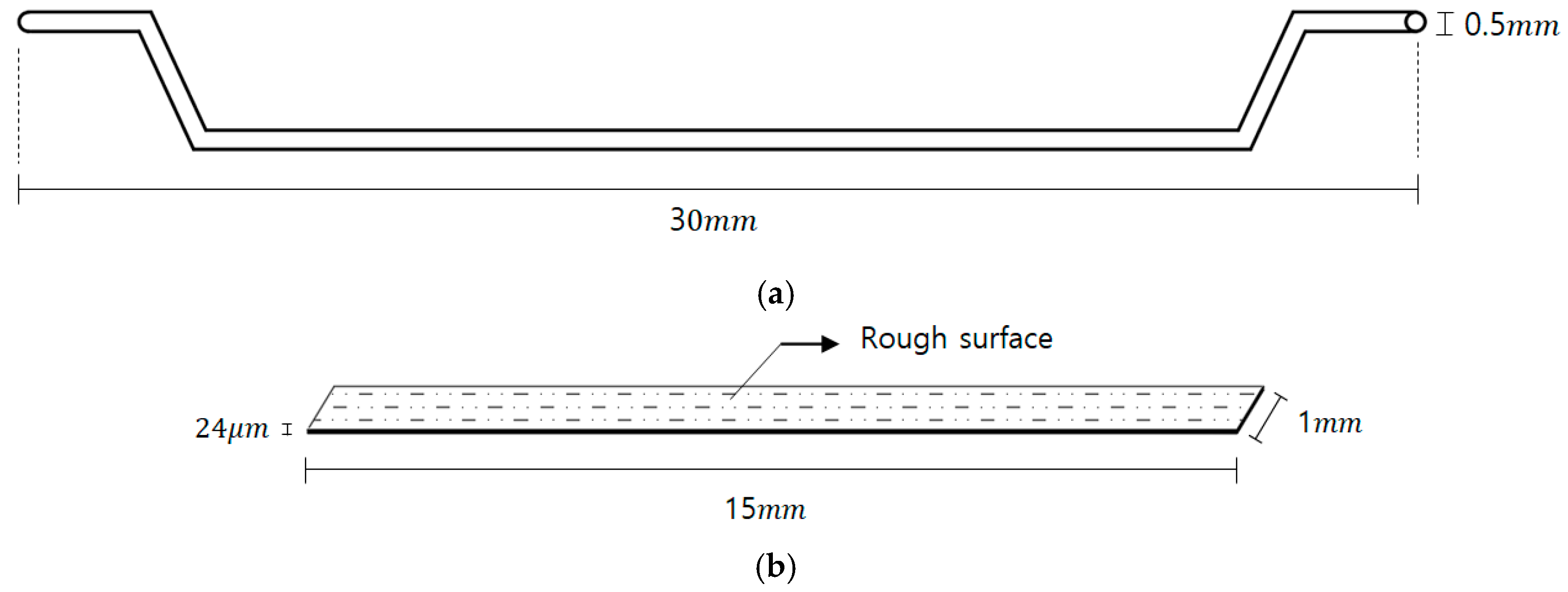
2.2. Materials
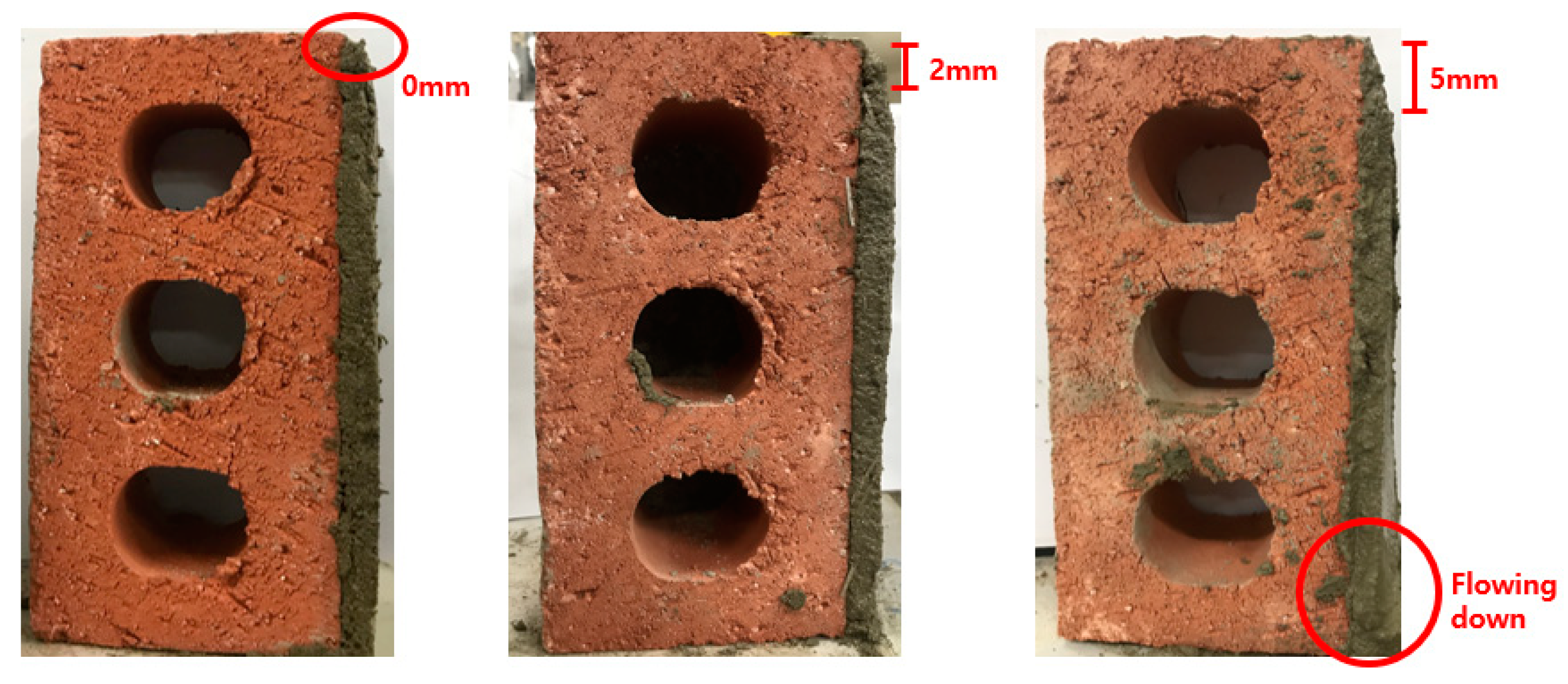
2.3. Workabiliy Tests
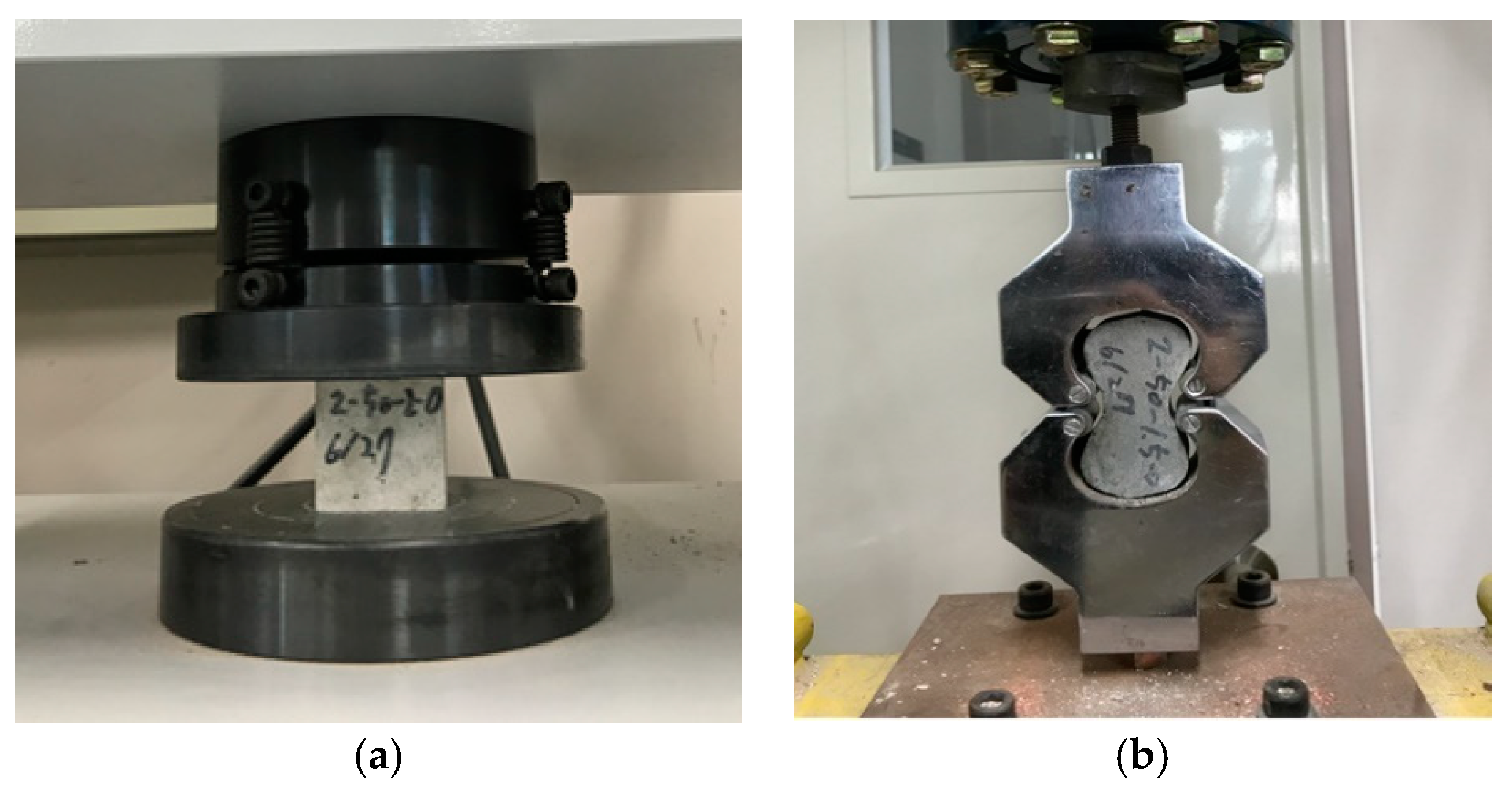
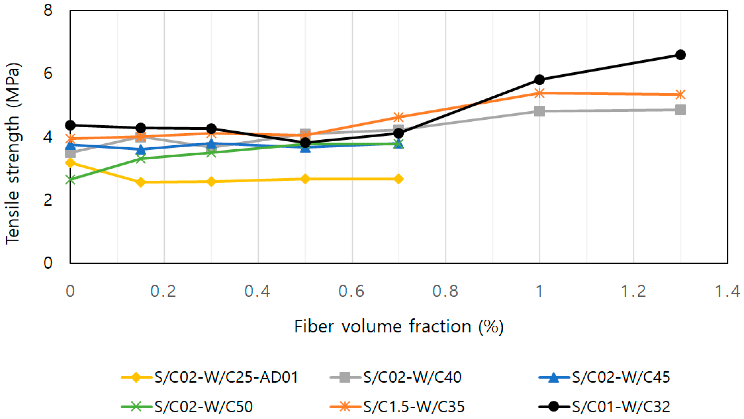
2.4. Compressive and Tensile Tests
2.5. Recommended Mixing Ratio
3. Test of Masonry Prisms Strengthened with SFRM Overlay
3.1. Test Program
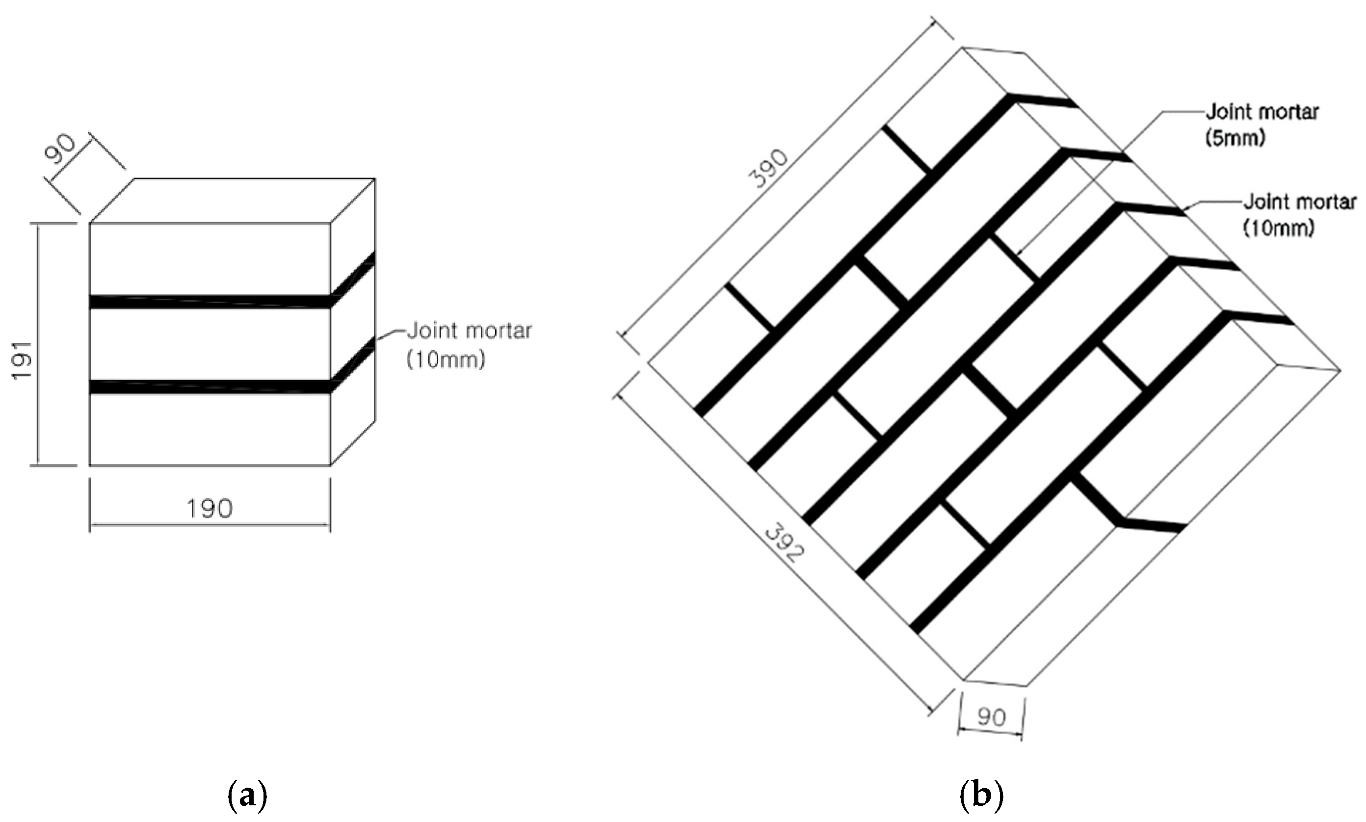
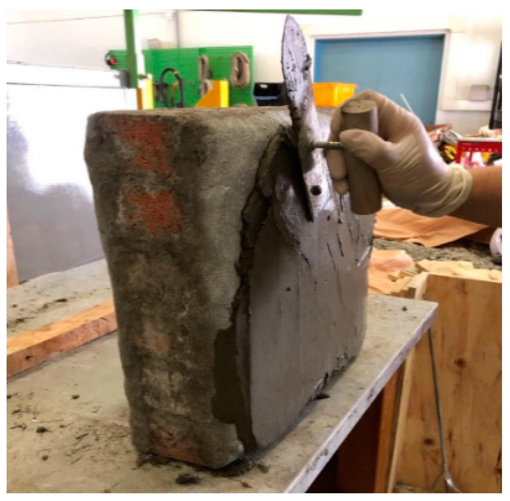
3.1.1. Specimens
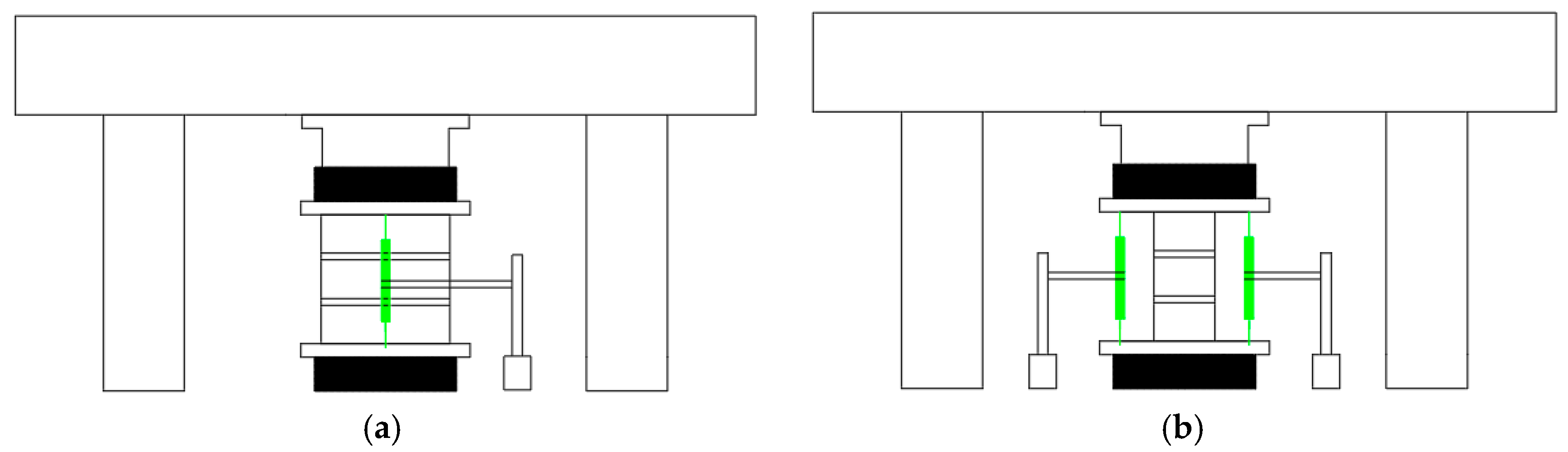
3.1.2. Test Setup and Loading Protocol
3.2. Result of Tests for Masonry Prisms
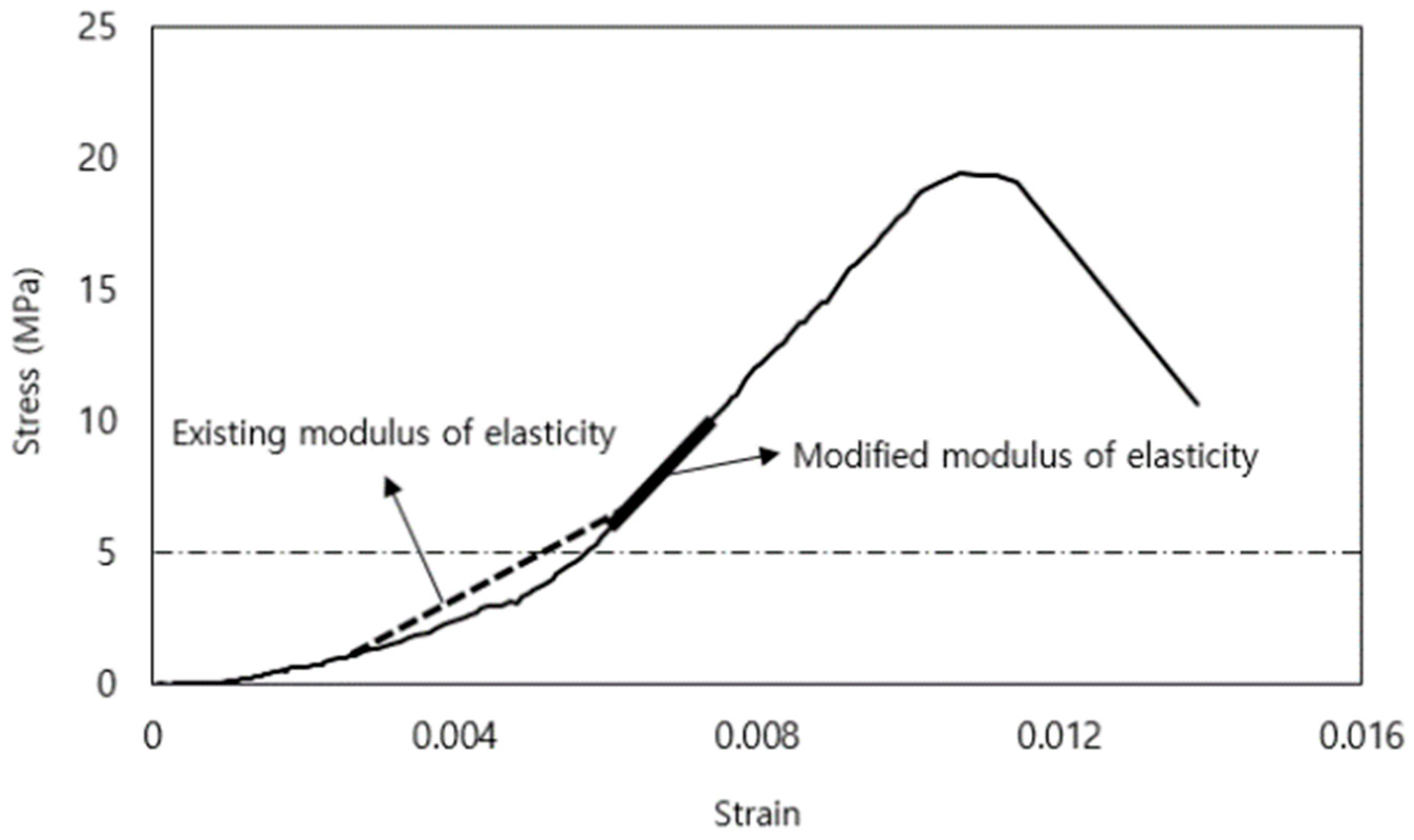
3.2.1. Strength and Modulus of Elasticity
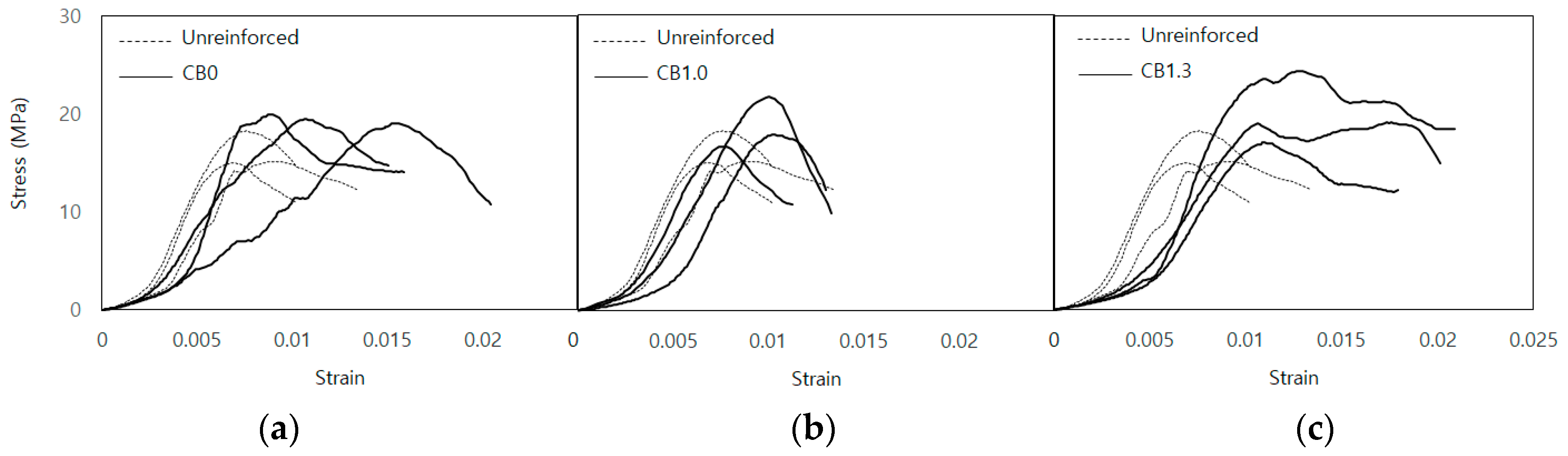
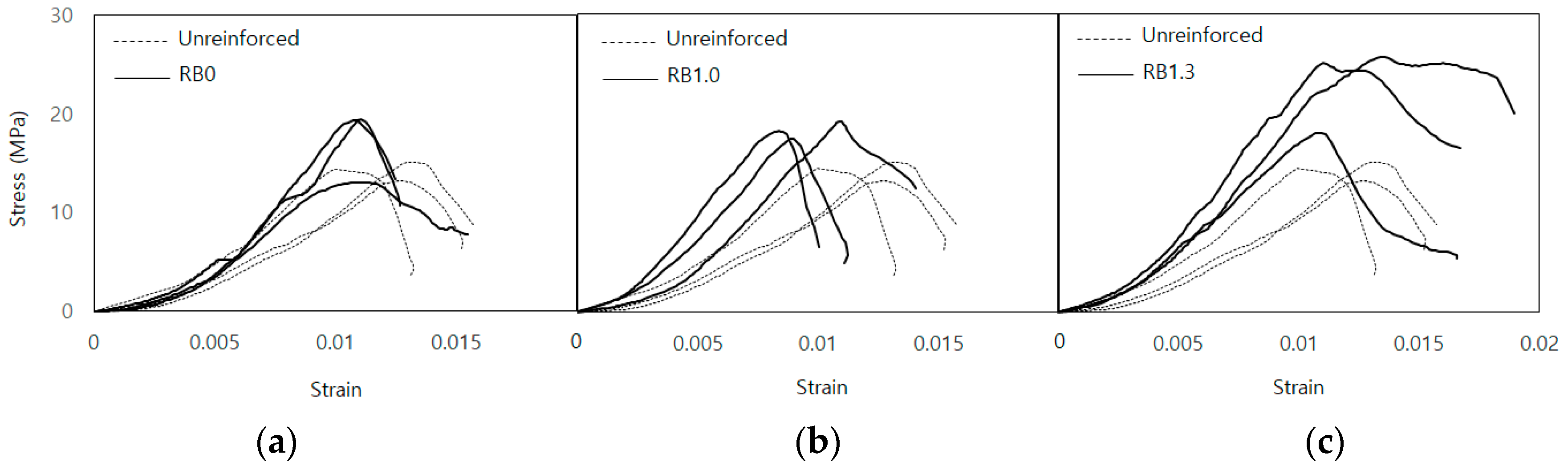
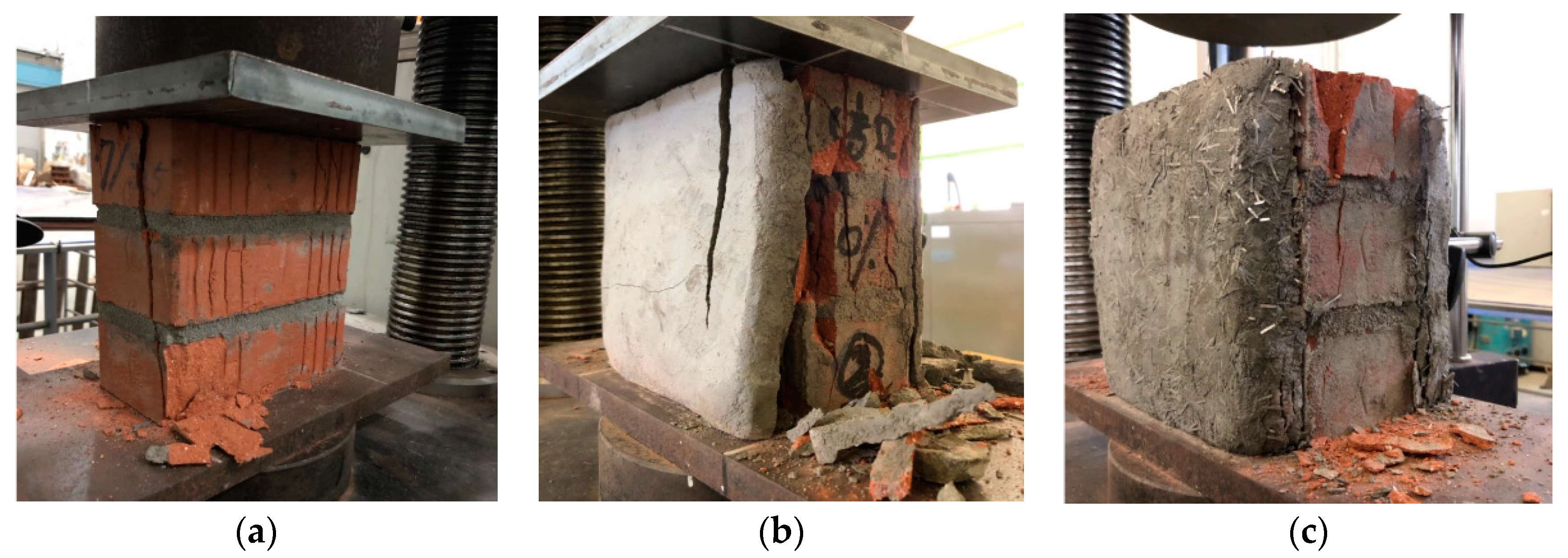
3.2.2. Compression Test Result
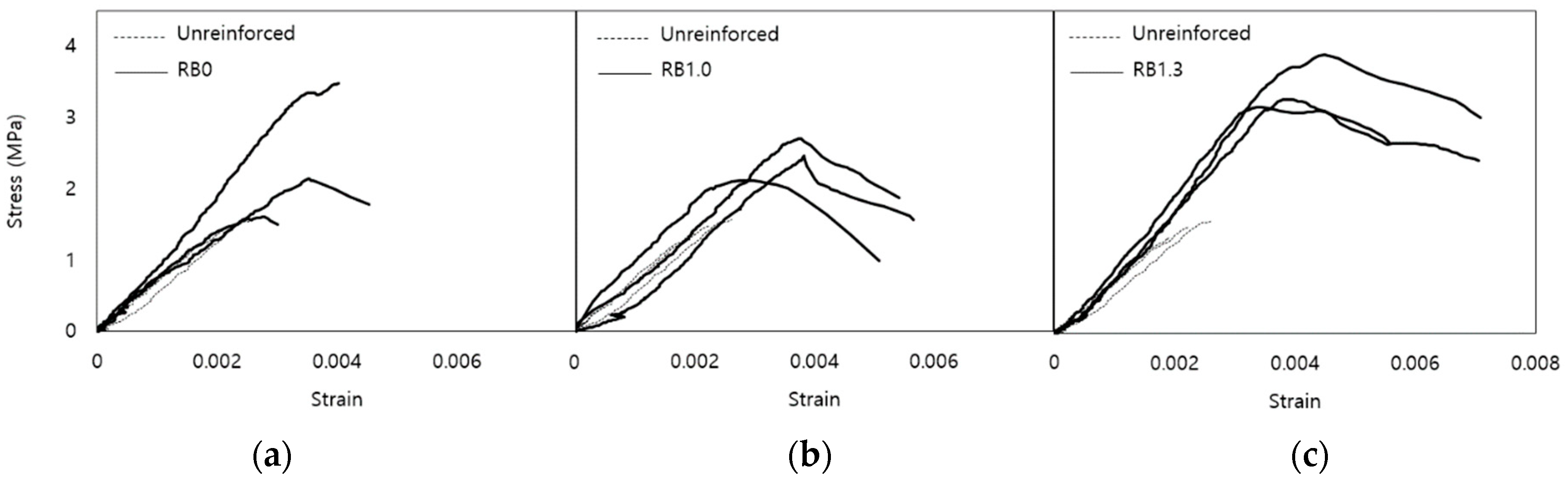
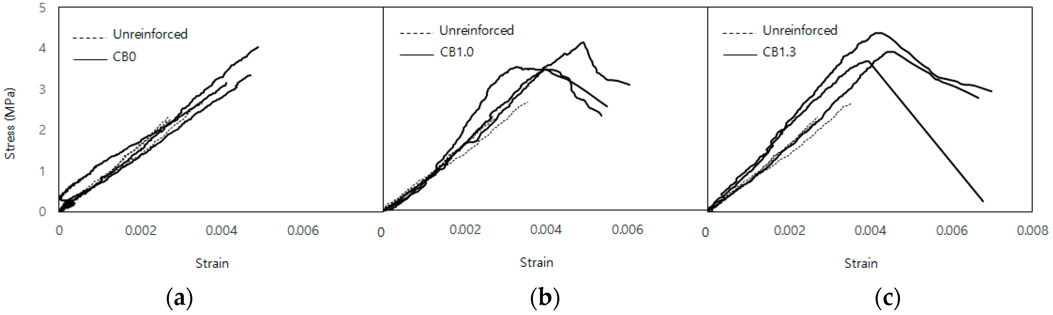
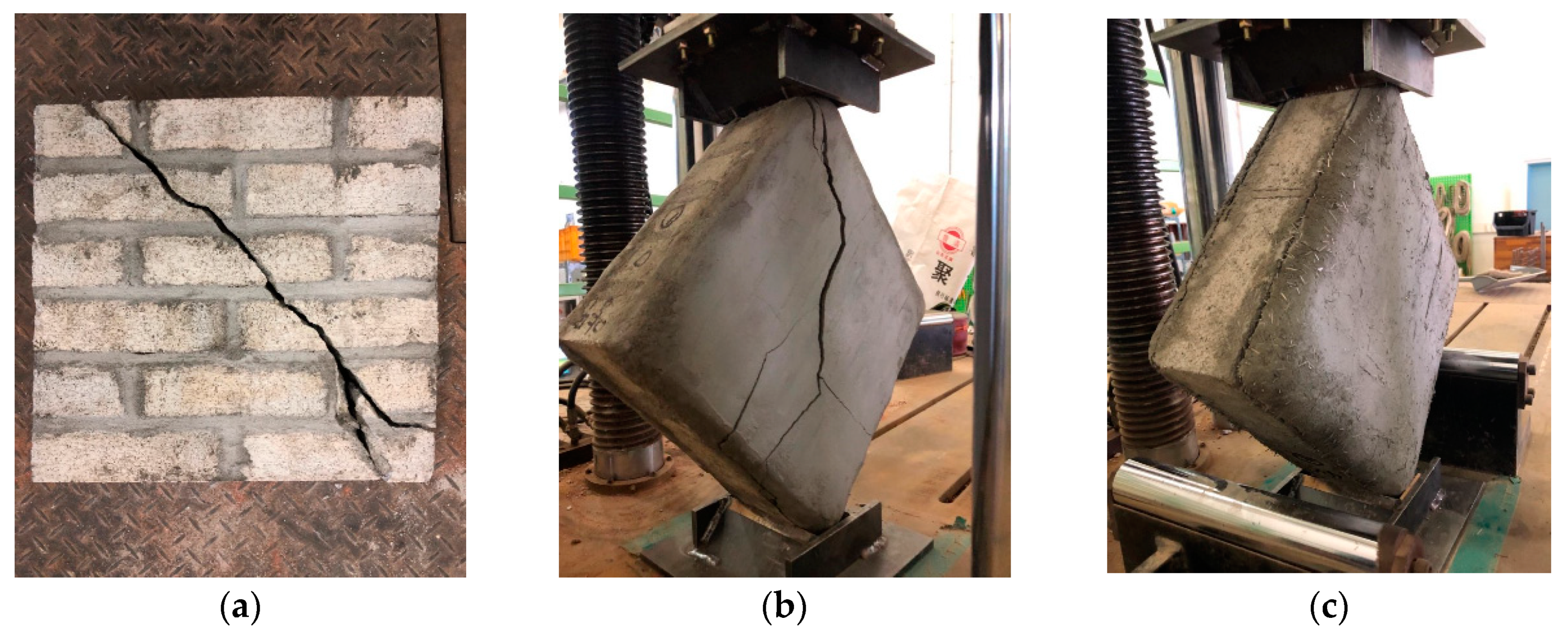
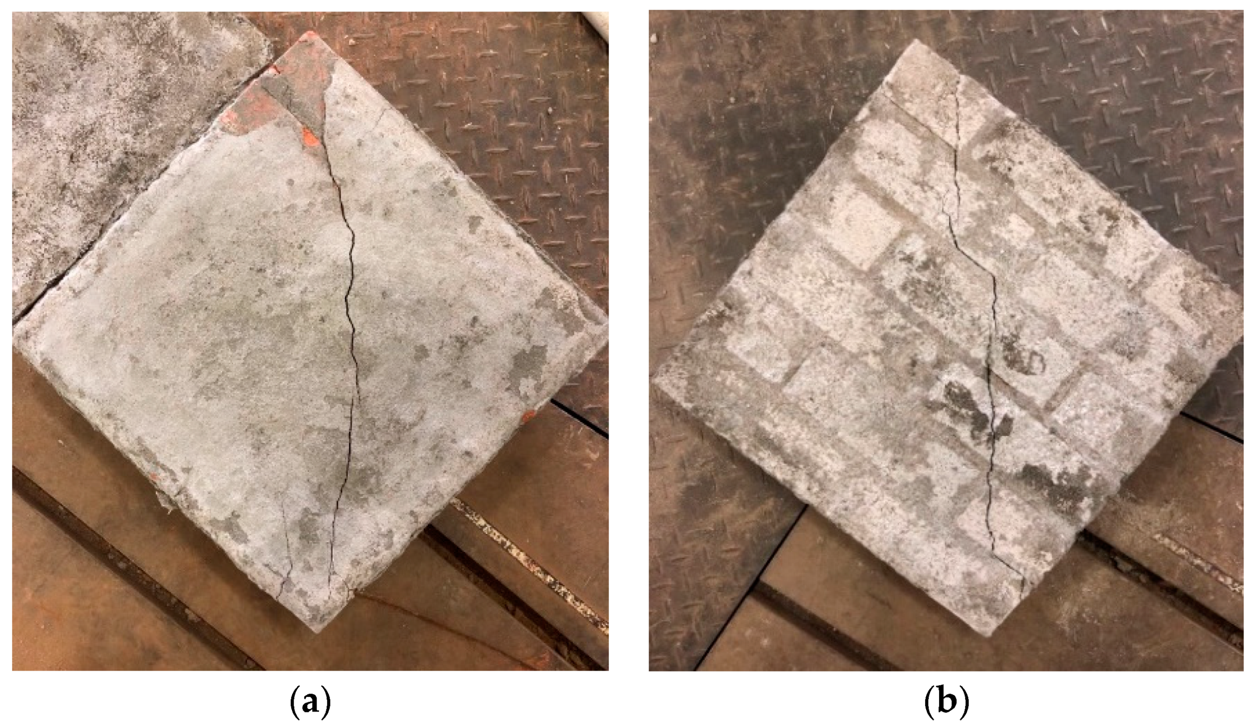
3.2.3. Diagonal Tension Test Result
4. Estimation of Enhanced Shear Strength
5. Conclusions
- The mixing ratios of SFRM appropriate for plastering work on masonry walls and effective in strengthening were identified. Plastering the SFRM was more effective for the shear strength than the compressive strength and achieved 67% and 138% increases for red clay brick prisms and concrete brick prisms;
- The higher volume fraction of amorphous steel fibers in SFRM e.g., 1.3% achieved considerably ductile behavior in the diagonal tension test in contrast to the brittle behavior observed for the plain mortar overlay;
- The SFRM overlay was separated without damage from the masonry prisms at the failure in diagonal tension tests. For accurate estimation of enhanced shear strength, it is necessary to take into account the bond strength between the SFRM overlay and the masonry, instead of the shear strength of SFRM overlay itself. Additionally, enhancement of the bond strength is expected to improve the strengthening effects by fully exploiting the capacity of the SFRM overlay;
- The masonry prisms used in this study have relatively good condition. In order to apply the proposed strengthening technique to existing masonry buildings in relatively poor conditions, additional verification for masonry in such a condition is necessary.
Author Contributions
Funding
Conflicts of Interest
References
- Vasconcelos, G.; Lourenço, P.B. Experimental characterization of stone masonry in shear and compression. Constr. Build. Mater. 2009, 23, 3337–3345. [Google Scholar] [CrossRef]
- Yu, H.R.; Kwon, K.H. A study on mechanical characteristics of masonry structure constructed by clay brick with lime mortar. J. Korea Inst. Struct. Maint. Insp. 2011, 15, 87–98. [Google Scholar]
- Kim, H.C.; Kim, K.J.; Park, J.H.; Hong, W.K. Experimental study on the material properties of unreinforced masonry considering earthquake load. J. Earthq. Eng. Soc. Korea 2001, 5, 93–101. [Google Scholar]
- Yang, K.H.; Lee, Y.J.; Hwang, Y.H. Evaluation of stress-strain relationship by diagonal tension of masonry assemblages. J. Korea Concrete Inst. 2019, 31, 537–544. [Google Scholar] [CrossRef]
- Choi, H.K.; Park, B.K.; Bae, B.I.; Choi, C.S. Lateral resistance of unreinforced masonry walls retrofitted with ECC. J. Archit. Inst. Korea 2010, 26, 3–10. [Google Scholar]
- Taghdi, M.; Bruneau, M.; Saatcioglu, M. Seismic retrofitting of low-rise masonry and concrete walls using steel strips. ASCE J. Struct. Eng. 2000, 126, 1017–1025. [Google Scholar] [CrossRef]
- Ghiassi, B.; Marcari, G.; Oliveira, D.V.; Lourenço, P.B. Numerical analysis of bond behavior between masonry bricks and composite materials. Eng. Struct. 2012, 43, 210–220. [Google Scholar] [CrossRef] [Green Version]
- Ismail, N.; Petersen, R.B.; Masia, M.J.; Ingham, J.M. Diagonal shear behavior of unreinforced masonry wallettes strengthened using twisted steel bars. Constr. Build. Mater. 2011, 25, 4386–4393. [Google Scholar] [CrossRef]
- Darbhanzi, A.; Marefat, M.S.; Khanmohammadi, M. Investigation of in-plane seismic retrofit of unreinforced masonry walls by means of vertical steel ties. Constr. Build. Mater. 2014, 52, 122–129. [Google Scholar] [CrossRef]
- Silva, B.; Benetta, M.D.; da Porto, F.; Modena, C. Experimental assessment of in-plane behaviour of three-leaf stone masonry walls. Constr. Build. Mater. 2014, 53, 149–161. [Google Scholar] [CrossRef]
- Almeida, J.A.P.P.; Pereira, E.N.B.; Barros, J.A.O. Assessment of overlay masonry strengthening system under in-plane monotonic and cyclic loading using the diagonal tensile test. Constr. Build. Mater. 2015, 94, 851–865. [Google Scholar] [CrossRef] [Green Version]
- D’Ambrisi, A.; Mezzi, M.; Caporale, A. Experimental investigation on polymeric net-RCM reinforced masonry panels. Compos. Struct. 2013, 105, 207–215. [Google Scholar] [CrossRef]
- Benedetti, A. In plane behaviour of masonry walls reinforced with mortar coatings and fibre meshes. Int. J. Archit. Herit. 2019, 13, 1029–1041. [Google Scholar] [CrossRef]
- ASCE 41-17. Seismic Evaluation and Retrofit of Existing Buildings; ASCE: Reston, VA, USA, 2017. [Google Scholar]
- Korea Construction Standards 41 16 02. Cement Mortar Plastering; Ministry of Land, Infrastructure and Transport: Seoul, Korea, 2018.
- Jo, C.G.; Han, S.J.; Kwon, M.H.; Lim, C.K. Seismic performance evaluation of reinforced concrete columns by applying steel fiber-reinforced mortar at plastic hinge region. J. Korea Concrete Inst. 2012, 24, 241–248. [Google Scholar]
- Kwon, Y.M. Mechanical Properties of High Strengh Concrete with Compositeness Fiber. Master’s Thesis, Kyungpook National University, Dajeon, Korea, 2016. [Google Scholar]
- Ha, G.J.; Shin, J.H. Evaluation of seismic performance of high strength reinforced concrete exterior beam-column joints using high ductile fiber-reinforced mortar. J. Korea Concrete Inst. 2013, 25, 419–428. [Google Scholar] [CrossRef] [Green Version]
- Park, M.S.; Shin, S.Y.; Jeong, E.C.; Kim, Y.S. A study on the mechanical property of high strength mortar reinforced with hybrid fibers. J. Archit. Inst. Korea 2016, 32, 49–56. [Google Scholar]
- Shabdin, M.; Zargaran, M.; Attari, N.K.A. Experimental diagonal tension (shear) test of un-reinforced, masonry (URM) walls strengthened with textile reinforced mortar (TRM). Constr. Build. Mater. 2017, 164, 704–715. [Google Scholar] [CrossRef]
- Lee, B.C.; Choi, S.J. The fluidity and hardened properties of fiber reinforced mortar by amorphous metallic fiber ratios. J. Archit. Inst. Korea 2014, 30, 51–58. [Google Scholar]
- Ku, D.O.; Kim, S.D.; Kim, H.S.; Choi, K.K. Flexural performance characteristics of amorphous steel fiber-reinforced concrete. J. Korea Concrete Inst. 2014, 26, 483–489. [Google Scholar] [CrossRef] [Green Version]
- FibraFlex. Saint-Gobain SEVA. Available online: http://www.fibraflex.com (accessed on 8 September 2020).
- Korea Standards F 4716. Cement Filling Compound for Surface Preparation; Korea Agency for Technology and Standard: Seoul, Korea, 2016.
- Korea Standards F 2262. Testing Method of Cement Mortar for Plastering; Korea Agency for Technology and Standard: Seoul, Korea, 2017.
- Korea Construction Standards 41 16 01. Plaster Work; Ministry of Land, Infrastructure and Transport: Seoul, Korea, 2018.
- Lee, H.W. An Experimental Study on the Fire-resistance Performance of Light-weight Aggregate Mortar for Plaster with Gypsum. Master’s Thesis, Konkuk University, Seoul, Korea, 2009. [Google Scholar]
- Park, G.J. A Study Use Diversification of Mortar for an Indoor Wall Plastering. Master’s Thesis, Chungnam National University, Dajeon, Korea, 2010. [Google Scholar]
- Korea Standards L 5111. Flow Table for Use in Tests of Hydraulic Cement; Korea Agency for Technology and Standard: Seoul, Korea, 2017.
- Korea Standards L 5105. Testing Method for Compressive Strength of Hydraulic Cement Mortars; Korea Agency for Technology and Standard: Seoul, Korea, 2017.
- Korea Standards L 5104. Testing Method for Tensile Strength of Hydraulic Cement Mortars; Korea Agency for Technology and Standard: Seoul, Korea, 2017.
- ASTM C1314. Standard Test Method for Compressive Strength of Masonry Prisms; ASTM International: West Conshohocken, PA, USA, 2014. [Google Scholar]
- ASTM E519/E519M. Standard Test Method for Diagonal Tension (Shear) in Masonry Assemblages; ASTM International: West Conshohocken, PA, USA, 2015. [Google Scholar]
- Korea Standards L 4004. Concrete Bricks; Korea Agency for Technology and Standard: Seoul, Korea, 2018.
- Korea Construction Standards 41 34 02. Bricklayers Work; Ministry of Land, Infrastructure and Transport: Seoul, Korea, 2018.
- Yi, W.H.; Lee, J.H.; Kang, D.W.; Yang, W.J. An experimental study on material characteristics of brick masonry. J. Archit. Inst. Korea 2004, 20, 45–52. [Google Scholar]
- Architectural Institute of Korea. Korean Building Code 2016; AIK: Seoul, Korea, 2016. [Google Scholar]
- Borri, A.; Castori, G.; Corradi, M. Shear behavior of masonry panels strengthened by high strength steel cords. Constr. Build. Mater. 2011, 25, 494–503. [Google Scholar] [CrossRef]
- ACI Committee 549. Guide to Design and Construction of Externally Bonded Fabric-Reinforced Cementitious Matrix (FRCM) Systems for Repair and Strengthening Concrete and Masonry Structures (ACI 549.4R-13); American Concrete Institute: Farmington Hills, MI, USA, 2013. [Google Scholar]
- Li, T.; Galati, N.; Tumialan, J.G.; Nanni, A. Analysis of unreinforced masonry concrete walls strengthened with glass fiber-reinforced polymer bars. ACI Struct. J. 2005, 102, 569–577. [Google Scholar]
- Silva, P.F.; Yu, P.; Nanni, A. Monte Carlo simulation for validating the in-plane shear capacity of URM walls strengthened with GFRP grid reinforced polyurea. J. Compos. Constr. ASCE 2008, 12, 405–415. [Google Scholar] [CrossRef]
- Sagar, S.L.; Singhal, V.; Durgesh, C.R.; Gudur, P. Diagonal shear and out-of-plane flexural strength of fabric-reinforced cementitious matrix-strengthened masonry wallets. J. Compos. Constr. ASCE 2017, 21, 405–415. [Google Scholar] [CrossRef]


| Precedent Research | Cement:SAND 1 | W/C Ratio (%) 2 |
|---|---|---|
| Jo et al. (2012) [16] | 1:1.7 | 45 |
| Kwon (2016) [17] | 1:1.5 | 45 |
| Ha and Shin (2013) [18] | 1:1 | 48 |
| Park et al. (2016) [19] | 1:1.6 | 22.5 (Admixture 1%) |
| Shabdin et al. (2017) [20] | 1:2 | 40 (Admixture 0.1%) |
| Specimen | Cement:SAND 1 | W/C Ratio (%) 2 | Admixture (%) 2 | Fiber Volume Fraction (%) |
|---|---|---|---|---|
| S/C20-W/C25-AD01 | 1:2 | 25 | 1 | 0, 0.15, 0.3, 0.5, 0.7 |
| S/C20-W/C40 | 1:2 | 40 | - | |
| S/C20-W/C45 | 1:2 | 45 | - | |
| S/C20-W/C50 | 1:2 | 50 | - | |
| S/C15-W/C35 | 1:1.5 | 35 | - | 0, 0.15, 0.3, 0.5, 0.7, 1.0, 1.3 |
| S/C10-W/C32 | 1:1 | 32 | - |
| Type | Amorphous Steel Fiber |
|---|---|
| Specific gravity | 7.25 |
| Tensile strength | 1400 |
| Fiber thickness | 24 |
| Fiber length | 15 |
| Fiber width | 1 |
| Slenderness | 83 |
| Equivalent diameter () | 0.18 |
| Shape | Flat and straight |
| Specimen | Fiber Volume Fraction (%) | Flow Value (mm) | Overlayable Thickness (mm) |
|---|---|---|---|
| S/C20-W/C25-AD01 | 0 | 215 | 7.5 |
| 0.15 | 221 | 7.5 | |
| 0.3 | 228 | 7.5 | |
| 0.5 | 222 | 5 | |
| 0.7 | 227 | 5 | |
| S/C20-W/C40 | 0 | 187 | 12.5 |
| 0.15 | 188 | 12.5 | |
| 0.3 | 190 | 15 | |
| 0.5 | 180 | 15 | |
| 0.7 | 177 | 7.5 | |
| 1.0 | 176 | 7.5 | |
| 1.3 | 154 | 5 | |
| S/C20-W/C45 | 0 | 206 | 12.5 |
| 0.15 | 207 | 10 | |
| 0.3 | 206 | 12.5 | |
| 0.5 | 196 | 12.5 | |
| 0.7 | 192 | 10 | |
| S/C20-W/C50 | 0 | 236 | 7.5 |
| 0.15 | 247 | 7.5 | |
| 0.3 | 228 | 7.5 | |
| 0.5 | 230 | 7.5 | |
| 0.7 | 231 | 7.5 | |
| S/C15-W/C35 | 0 | 188 | 12.5 |
| 0.15 | 185 | 10 | |
| 0.3 | 183 | 12.5 | |
| 0.5 | 174 | 12.5 | |
| 0.7 | 177 | 10 | |
| 1.0 | 180 | 7.5 | |
| 1.3 | 171 | 5 | |
| S/C10-W/C32 | 0 | 198 | 10 |
| 0.15 | 192 | 15 | |
| 0.3 | 182 | 12.5 | |
| 0.5 | 178 | 12.5 | |
| 0.7 | 173 | 12.5 | |
| 1.0 | 182 | 10 | |
| 1.3 | 171 | 10 |
| Experiment | SFRM Mixing Ratio | |
|---|---|---|
| Workability | Flow | S/C20-W/C40 S/C15-S/C35 S/C10-W/C32 |
| Adhesion | S/C20-W/C45 S/C10-W/C32 | |
| Strength | Compressive | - |
| Tensile | S/C10-W/C32 | |
| Brick | SFRM Overlay | Fiber Volume Fraction (%) | Specimen Name | Number of Specimens | |
|---|---|---|---|---|---|
| Compression | Diagonal Tension | ||||
| Red clay brick | No | - | RP | 3 | 3 |
| 1 side | 1.0 | RS1.0 | 3 | 2 | |
| 1.3 | RS1.3 | 3 | 3 | ||
| 2 side | 0 | RB0 | 3 | 3 | |
| 1.0 | RB1.0 | 3 | 3 | ||
| 1.3 | RB1.3 | 3 | 3 | ||
| Concrete brick | No | - | CP | 3 | 3 |
| 1 side | 1.0 | CS1.0 | 3 | 2 | |
| 1.3 | CS1.3 | 3 | 3 | ||
| 2 side | 0 | CB0 | 3 | 3 | |
| 1.0 | CB1.0 | 3 | 3 | ||
| 1.3 | CB1.3 | 3 | 3 | ||
| Specimens | Average | Rate of Increase (%) | |||
|---|---|---|---|---|---|
| Peak Load (kN) | Compressive Strength (MPa) | Compressive Strength | |||
| RP | 244.6 | 14.5 | 1382.7 | - | - |
| RS1.0 | 305 | 18 | 2356.9 | 25% | 70% |
| RS1.3 | 380.3 | 22.5 | 2872.1 | 55% | 108% |
| RB0 | 296.9 | 17.5 | 2764.8 | 21% | 100% |
| RB1.0 | 311.1 | 18.4 | 2552.7 | 27% | 85% |
| RB1.3 | 394.9 | 23.3 | 2534.5 | 61% | 83% |
| Specimens | Average | Rate of Increase (%) | |||
|---|---|---|---|---|---|
| Peak Load (kN) | Compressive Strength (MPa) | Compressive Strength | |||
| CP | 275.6 | 16.3 | 3951.1 | - | - |
| CS1.0 | 317.1 | 18.7 | 4030.5 | 15% | 2% |
| CS1.3 | 323.6 | 19.1 | 4360.6 | 17% | 10% |
| CB0 | 334.4 | 19.8 | 3626.6 | 21% | −8% |
| CB1.0 | 319.9 | 18.9 | 3687.1 | 16% | −7% |
| CB1.3 | 348.3 | 20.6 | 3717.5 | 26% | −6% |
| Specimens | Average | Rate of Increase (%) | |||
|---|---|---|---|---|---|
| Load (kN) | Shear Strength (MPa) | Shear Strength | |||
| RP | 60.4 | 1.5 | 671.5 | - | - |
| RS1.0 | 101.4 | 2.4 | 621.7 | 68% | −7% |
| RS1.3 | 91 | 2.2 | 633.3 | 51% | −6% |
| RB0 | 100.2 | 2.4 | 699.1 | 66% | 4% |
| RB1.0 | 101.9 | 2.5 | 748.3 | 69% | 11% |
| RB1.3 | 143.7 | 3.5 | 884.6 | 138% | 32% |
| Specimens | Average | Rate of Increase (%) | |||
|---|---|---|---|---|---|
| Load (kN) | Shear Strength (MPa) | Shear Strength | |||
| CP | 120.2 | 2.4 | 810.3 | - | - |
| CS1.0 | 137.1 | 2.8 | 631.7 | 14% | −22% |
| CS1.3 | 167.2 | 3.4 | 843.1 | 39% | 4% |
| CB0 | 170.0 | 3.4 | 746.0 | 41% | −8% |
| CB1.0 | 187.1 | 3.8 | 892.6 | 56% | 10% |
| CB1.3 | 201.2 | 4.0 | 969.5 | 67% | 20% |
| Brick | Specimens | Analytical (kN) | Experimental (kN) | ||||||
|---|---|---|---|---|---|---|---|---|---|
| Equation (3) | Equation (4) | Equation (3) | Equation (4) | Equation (3) | Equation (4) | ||||
| Red clay brick | RS1.0 | 42.7 | 36.6 | 76.1 | 79.3 | 118.8 | 71.7 | 1.1 | 1.7 |
| RS1.3 | 41.7 | 84.4 | 84.4 | 127.1 | 64.3 | 1.3 | 2.0 | ||
| RB0 | 55.5 | 124.5 | 98.2 | 167.2 | 70.8 | 1.4 | 2.4 | ||
| RB1.0 | 73.2 | 152.1 | 115.9 | 194.8 | 72.0 | 1.6 | 2.7 | ||
| RB1.3 | 83.3 | 168.8 | 126.0 | 211.5 | 101.6 | 1.2 | 2.1 | ||
| Concrete brick | CS1.0 | 85.0 | 36.6 | 76.1 | 121.6 | 161.1 | 96.9 | 1.3 | 1.7 |
| CS1.3 | 41.7 | 84.4 | 126.6 | 169.4 | 118.2 | 1.1 | 1.4 | ||
| CB0 | 55.5 | 124.5 | 140.5 | 209.5 | 120.2 | 1.2 | 1.7 | ||
| CB1.0 | 73.2 | 152.1 | 158.2 | 237.1 | 132.3 | 1.2 | 1.8 | ||
| CB1.3 | 83.3 | 168.8 | 168.3 | 253.8 | 142.2 | 1.2 | 1.8 | ||
© 2020 by the authors. Licensee MDPI, Basel, Switzerland. This article is an open access article distributed under the terms and conditions of the Creative Commons Attribution (CC BY) license (http://creativecommons.org/licenses/by/4.0/).
Share and Cite
Yu, J.-H.; Park, J.-H. Investigation of Steel Fiber-Reinforced Mortar Overlay for Strengthening Masonry Walls by Prism Tests. Appl. Sci. 2020, 10, 6395. https://doi.org/10.3390/app10186395
Yu J-H, Park J-H. Investigation of Steel Fiber-Reinforced Mortar Overlay for Strengthening Masonry Walls by Prism Tests. Applied Sciences. 2020; 10(18):6395. https://doi.org/10.3390/app10186395
Chicago/Turabian StyleYu, Ji-Hoon, and Ji-Hun Park. 2020. "Investigation of Steel Fiber-Reinforced Mortar Overlay for Strengthening Masonry Walls by Prism Tests" Applied Sciences 10, no. 18: 6395. https://doi.org/10.3390/app10186395
APA StyleYu, J.-H., & Park, J.-H. (2020). Investigation of Steel Fiber-Reinforced Mortar Overlay for Strengthening Masonry Walls by Prism Tests. Applied Sciences, 10(18), 6395. https://doi.org/10.3390/app10186395