1. Introduction
Marine structures including oil containment booms, floating tunnel, pipelines and fish-farming float collars cannot avoid the effects of an oscillatory flow derived from the wave and relative structure motions. These marine structures can be viewed as a semi-submerged cylinder under oscillatory flow. The surface distortion and water fragmentation will result in a complicated response and hydrodynamic loads. This problem is still not fully understood and threatens the safety of the relevant marine structures. Thus, it is essential to study the hydrodynamic features of semi-submerged cylinder in an oscillatory flow for the marine structures design.
The current research of flow past a cylinder contains mainly three categories including cylinders submerged in infinite depth water, cylinders near the free surface and cylinders partially submerged under the water surface. In the oscillatory flow, many focuses are on the problem of flow past a fully immersed cylinder with infinite depth. Morison et al., (1953) [
1]; Morison et al., (1950) [
2] first raised a formula to calculate the in-line (IL) component of hydrodynamic force, which is now known as the Morison formula. The drag coefficient (
CD) and added mass coefficient (
Cm) in the Morison formula were found to be respectively of value 1.7 and 0.4 through an experimental study of stationary rigid cylinders under wave actions. The values of
CD and
Cm for a cylinder under the action of waves were further determined by Keulegan (1958) [
3] through Fourier analysis and it was found that the Stokes parameters have a significant influence on these coefficients. Mercier (1973) [
4] measured the force in the transverse direction, drag force and added-mass force (inertia) of the fully immersed cylinder in the oscillatory flow. The drag coefficient and added mass coefficient were witnessed to have good agreements with results of Keulegan (1958) [
3]. Justesen (1989) [
5] and Sarpkaya (2006) [
6] experimentally studied the effects of the Re number at low Keulegan-Carpenter (KC) numbers on a rigid stationary cylinder under this oscillatory flow. Moreover, Sarpkaya (1976) [
7] carried out a more comprehensive experimental studies on the forces of cylinders under oscillatory flows in sinusoidal form that was generated through an oscillatory U-shaped tube. The results were systematically reported that the hydrodynamic coefficients closely related with the Re number, Keulegan-Carpenter (KC) number and the relative roughness of the cylinder surface. Moreover, Williamson (1985) [
8] and Tatsumo and Bearman (1990) [
9] conducted a comprehensive flow visualization of the flow past cylinder, which provided a better understanding of the underlying fluid mechanism. Therefore, the investigation of hydrodynamic loads on the fully immersed cylinder with infinite depth in an oscillatory flow is relatively comprehensive.
Different from flow past the fully submerged cylinder with infinite depth, there are few studies focusing on cylinders near the free surface and cylinders partially submerged below the water surface in an oscillatory flow. As for close to free surface cylinders, the existing research mainly focuses on the steady flow field. Roshko (1975) [
10] investigated the drag and transverse forces and discussed the relationships of the drag force and the lift force respectively with a submerged gap ratio. Bearman and Zdravkovich (1978) [
11] further observed that the free surface can greatly influence the response frequency and the corresponding Strouhal number decreases quickly with the submerged gap ratio decreasing. Lei et al. (1999) [
12] experimentally investigated a cylinder under steady flow and highlighted the strong effects of the boundary layer development on this lift force. Different from the experimental studies, computational fluid dynamics (CFD) provides more opportunities to perform comprehensive studies on the underlying mechanisms of complicated fluid-structure interactions (FSI) problems. Reichl et al. (1997) [
13] and Sheridan et al. (1995) [
14] conducted numerical simulation of cylinders near a free surface under steady flow and studied corresponding motion behavior. The jet state and metastable behavior were noted by these researchers, at the free surface under certain gap ratio and Froude (Fr) number. The configuration of a partially submerged cylinder under flow is an unavoidable and actually widely observed problem for float collars of the fish farming structures and numerous studies were conducted in the literature of the flow past float collars. For example, Triantafyllou and Dimas (1989) [
15] studied the stability of a semi-submerged cylinder under flow, where results are influenced by the Fr number. At all downstream locations, convective instability of the wake is also observed based on the computation of potential flow theory. However, potential flow theory precludes the effect of the free surface and fluid viscosity, which cannot be ignored for a partially submerged cylinder. As a result, it is questionable whether traditional diffraction and radiation theories will provide a complete answer for this problem. Kristiansen and Faltinsen (2008) [
16] and Kristiansen (2010) [
17] experimentally measured the sway and heave motion of a semi-submerged circular cylinder under action of waves. Fu et al. (2013) [
18] experimentally investigated hydrodynamic loads of semi-submerged cylinders that are employed in fish farming systems. It is reported that the effects of free surface are critically important for the hydrodynamic coefficients including drag coefficients and added mass coefficients in the IL direction; the direction parallel to the oscillatory flow. However, hydrodynamic forces and coefficients in the cross-flow (CF) direction have not yet been revealed and considered into models and this relationship between hydrodynamic loads and Froude number has not been studied.
Recently, Ren et al. (2019) [
19] conducted experiments of the partially submerged cylinder with different submerged depths in steady flow. Surprisingly, the mean downward transverse force is witnessed to be significant, which catches more and more attentions from both academia and industry. The lift coefficient was found to be greatly affected by Froude number. However, the understanding of hydrodynamic load in the CF direction on the semi-submerged cylinder under the oscillatory flow is still blank and potential influence parameters were not studied comprehensively. Therefore, it is urgent to investigate the hydrodynamic features of the semi-submerged cylinder in an oscillatory flow, especially for the lift coefficient and providing a further understanding for relevant structural design.
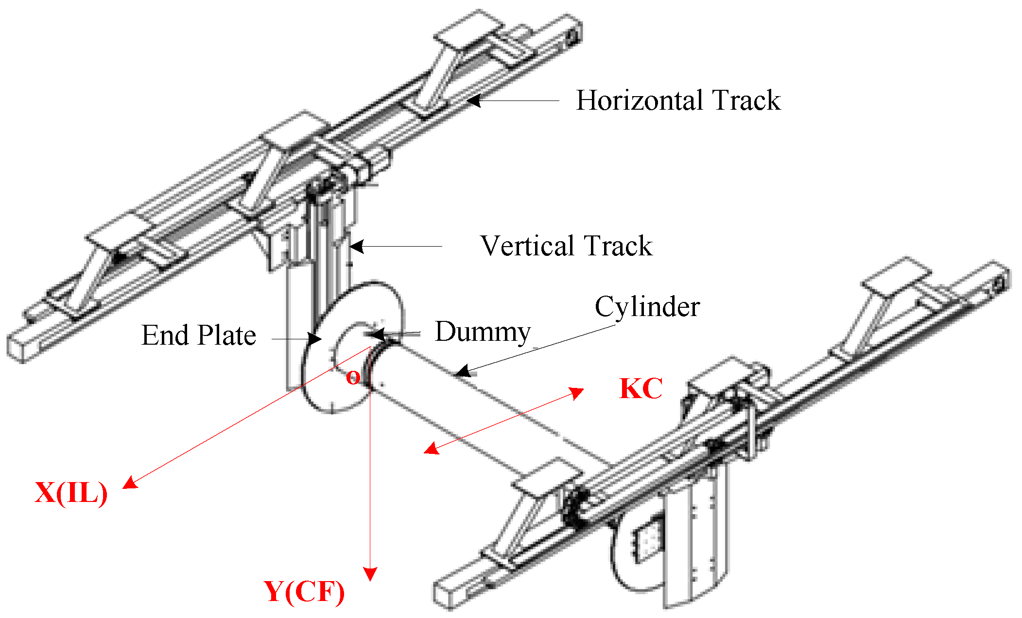
In this study, model tests of semi-submerged cylinders in an oscillatory flow were carried out in a towing tank. The rigid cylinder was enforced to oscillate harmonically under numerous combinations of periods and amplitudes to generate an equivalent oscillatory flow. The KC number was designed to range from 6.3 to 37.7. The Stokes number and corresponding Froude number varied from 5434.7 to 11,363.6 and from 0.12 to 1.55, respectively. The hydrodynamic force in both IL and CF directions and the displacement in the IL direction were measured. We also establish the method for identifying the drag and added mass coefficients in the IL direction. Based on the observations of the lift force, a novel empirical prediction method of lift force is first proposed. The features of hydrodynamic loads, the relationships between hydrodynamic coefficients and influential parameters are further studied and discussed.
The remainder of this paper is organized as what follows.
Section 2 describes the experimental set-up, test arrangement and definition of the key parameters such as Froude number, Stokes number and KC number. In
Section 3, the identification of the drag and added mass coefficient are presented. Then, main results including hydrodynamic load features, the relationships among the drag, added mass, lift coefficients of the semi-submerged cylinder and influential parameters as well as a novel empirical prediction method of lift force are discussed in
Section 4. The main conclusions and future work directions are summarized in
Section 5.
3. Identification Method of Hydrodynamic Coefficients
According to the Morison equation [
1,
2], the hydrodynamic force in the IL direction can be decomposed into two components; that is, the drag force and the inertial force that are respectively proportional to the square of the velocity and the acceleration. The similar equation was also employed to describe the hydrodynamic force on floating cylinder in the horizontal direction [
18]. Thus, the total force can be expressed as,
For convenience, it is assumed that,
Then, Equation (8) can be simplified as,
The least squares method is used to estimate the drag coefficient
CD and added mass coefficients
Cm in the IL direction, which minimizes the sum of the squared difference
J(
CD, Cm) between the predicted and measured force, which can be written as,
where
FX(
t) is the measured force and
n is the sample number.
In order to minimize the difference between the identified and predicted values of the hydrodynamic force, Equation (11) should be satisfied,
Transforming Equation (12) into matrix form, we have
where,
The drag and added mass coefficients can be expressed as,
However, there is no mature empirical equation to describe the hydrodynamic force in the CF direction. The empirical prediction of the lift force will be further studied in
Section 4.3 according to the features observed by our experiments in this paper.
4. Results and Discussion
This section first describes the main features of hydrodynamic forces on the semi-submerged cylinder under oscillatory flow. Based on observed features, we then proposed a novel empirical formula that reduces the parameters required to determine lift force but is demonstrated to well predict the lift force. Furthermore, we perform a comprehensive study on the influence of KC number, Stokes number, Froude number on the drag coefficient and added mass coefficient for the IL direction as well as lift coefficients and phase difference for the prediction of lift force in the CF direction. The phenomena including slamming and overtopping are also observed and discussed.
4.1. Hydrodynamic Forces on the Semi-Submerged Cylinder
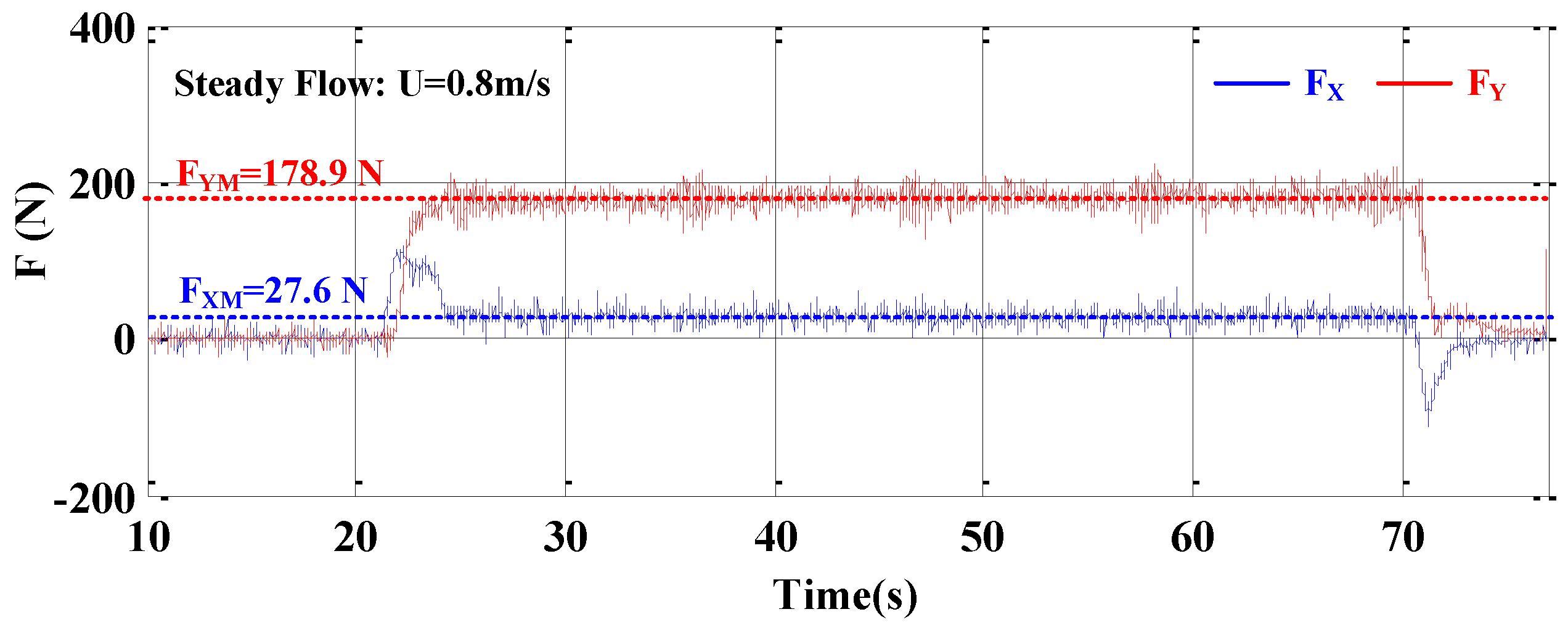
As shown in
Figure 4, the time history of the hydrodynamic loads on a semi-submerged cylinder under the steady flow velocity of U = 0.8 m/s was presented. The blue and red solid lines respectively represent the hydrodynamic forces in the IL and CF directions. The mean force in the IL direction
FXM and mean lift force in the CF direction
FYM are 27.6 N and 178.9 N, respectively. A novel phenomenon of an obvious mean downward lift force is witnessed for semi-submerged cylinder and reported by Ren et al. (2019) [
19]. This mean lift force is greater than the drag force and should be considered in the real engineering projects.
For the hydrodynamic force on semi-submerged cylinder in an oscillatory flow, the time history of these forces in both IL and CF directions for KC = 18.8 and
β = 111,364 is shown in
Figure 5. Similar to hydrodynamic force on semi-submerged cylinder in steady flow, the mean downward force in the CF direction
FYM can be obviously witnessed. The values of
FYM were 162.3 N for KC = 18.8 at
β = 111,364, while no mean values of the force in the IL direction can be observed. The mean lift force in the CF direction can reach and even exceed the fluctuating force amplitude of hydrodynamic force in the IL direction (
FX). The fluctuating components of two forces are in the same magnitudes.
From the spectrum of the hydrodynamic forces in both IL and CF directions as shown in
Figure 5c, the dominant frequency of force in the IL direction is the same as expected for the forced motion frequency (
fo) of 0.18 Hz and the response frequency in the CF direction is found to be always dominated by twice the value of
fo (
f = 0.36 Hz) under KC = 18.8 and
β = 111,364. It indicates that this lift force with higher frequency could cause more severe damage to related structures and cannot be neglected.
To understand the background mechanics of the mean lift downward force in an oscillatory flow, a camera is placed on the apparatus to record the surface waveforms.
Figure 6a clearly shows the recorded local surface distortions. According to the phenomenon recorded by the camera, we infer that the mean downward lift force can be attributed to the asymmetric flow field and the pressure difference between the top and bottom of the cylinder [
19,
23] as shown in
Figure 7c. Furthermore,
Figure 7 presents the time history of hydrodynamic force and sketches of flow field around cylinder in one period to give more detailed features. Combining with forced motion velocity, we observed that the lift force reaches its amplitude value at around time points I, III, V. From
Figure 7c, the top-sided flow velocity is more significant when the forced motion velocity reach its maximum (
Umax). Thus, the maximum lift force value appears near the time points of
Umax.
However, there is a phase difference between FYmax and Umax. These two maximum values do not reach at the same time. The maximum of force FYmax is reached before the Umax. It may be related to the effects of the exciting wave. The velocity of the exciting wave will be superimposed with the forced motion velocity. The time of the “real velocity” superimposed by the velocity of exciting wave and the forced motion reach the maximum value is not located at that of forced motion velocity amplitude. More insightful experiments and CFD simulations will be carried out in the near future to further investigate this phenomenon. This phase difference would be an important parameter to describe the relationship between the lift force and flow velocity generated by forced motion.
Beyond that, a shock signal of the force in the IL direction appears when the cylinder reverses its motion direction (II, IV). The phenomenon is caused by the “slamming” phenomenon as shown in
Figure 6a.
Figure 6b shows the developing process sketch of the slamming. When the cylinder move forward, the water attached on the cylinder and exciting wave will be moved in the same direction as the cylinder. As the cylinder reverse its moving direction, the attaching water and exciting wave cannot change their movement direction immediately. The cylinder will strike the exciting wave and attaching water. The water climbs significantly in an instant and results in an impulse force in the IL direction. Slamming will result in high pressure and introduce damage on local structure and subsequent failure of the entire system. Thus, it is necessary to take some considerations to the local structure designs.
4.2. Empirical Prediction of the Lift Force for Semi-Submerged Cylinder in Oscillatory Flow
As previously mentioned in
Section 4.1, the lift force fluctuates at a frequency twice the forced motion frequency and an obvious phase difference between the force and velocity motion can be observed. Moreover, the mean value is found to be the main feature of the lift force in the CF direction. However, there is no empirical formula for lift force on semi-submerged cylinder in an oscillatory flow. In the real engineering project design, it is very difficult to efficiently determine the hydrodynamic force on these relevant marine structures. To reasonably describe the relationship between the lift force and flow velocity, above main features should be satisfied and thus we further propose the application of this empirical prediction of the lift force to partially submerged cylinder under an oscillatory flow:
where
FYP is the predicted lift force in the CF direction.
CL is lift force coefficient and
τ is a time delay representing a phase difference. For convenience of description, the phase difference
φ is expressed as,
The Equation (16) can be simplified as,
Expanding Equation (18) out, we obtain
From Equation (19), the predicted force can satisfy the main features observed in
Section 4.1 and can be divided into two parts—the mean lift force
FYPM and twice the forced motion frequency fluctuating lift force
FYPo.
Through Equation (20), the lift coefficient can be calculated by,
where
FYM is the measured mean lift force in the CF direction.
Here, Equation (18) only has two parameters that remain to be determined, the lift coefficient
CL and the phase difference
φ. However, if we attempt to directly describe the lift force as the mean and fluctuating component, we need to determine four parameters including the mean value, fluctuating frequency, fluctuating amplitude and phase difference. This novel empirical formula in Equation (18) directly assigns the fluctuating frequency as twice of the frequency of oscillatory flow and the fluctuating amplitude the same as the mean value, which reduced undetermined parameters from four to two. This reduction is directly based on our observation of the main feature of the measured lift force; for example, red line in
Figure 6b. In the following, we demonstrate that such a reduction of parameters still well predicts the fluctuating lift force in a range of KC number, Froude number and Stokes number.
To determine the value of
φ, the sum of the squared difference
J1(
φ) between the predicted and measured fluctuating force, which can be expressed as,
Figure 8 presents the value of
J1(
φ) versus phase difference angle
φ under KC = 18.8 at
β = 11,364. It can be seen that
J1(
φ) minimizes at
φ = 21°. Thus, the phase difference angle at this case is adopted as 21°. Using the same method, the value of
φ for each test case can be obtained. To validate the predicted method, the identified lift coefficient and phase angle are substituted into the predicted formula of Equation (18). The recalculated lift force and measured force in an oscillatory flow are shown in
Figure 9. The blue dashed and red solid line respectively represents the measured and calculated force. The calculated forces are in a good agreement with the measured forces. Therefore, it is feasible and promising to use the prediction formula described in Equation (18) to calculate the hydrodynamic force in the CF direction in an oscillatory flow. Such a good agreement using this novel empirical formula in Equation (18) also provides a potential explanation of the mechanism of the fluctuating lift force with frequency twice of the oscillatory flow, which is worthwhile for further study through flow visualization and CFD.
Moreover, for computational fluid dynamics, this problem is a typical two-phase flow problem, which is not simple to solve. However, this empirical formula can greatly avoid the complicated and time-consuming hydrodynamic calculation problem and will be very efficient and convenient for engineer to calculate the force on semi-submerged cylinder, such as the floating collar of fish farming. However, in real engineering project, the semi-submerged cylinder will not have a constant vertical displacement, which is likely to result in a different lift force. This work mainly focused on the static semi-submerged status of the cylinder, which will also provide a preliminary estimation of the lift force and basic references for further investigation. More systematic experiments will be carried out to determine the influence of vertical and horizontal vibration and even the submerged depths on hydrodynamic load in near future.
4.3. Drag and Added Mass Coefficients for Semi-Submerged Cylinder
Combining measured hydrodynamic force and forced motion in the IL direction, we can calculate the drag coefficient (
CD) and added mass coefficient (
Cm) using the method proposed in
Section 3. To verify the identified method of hydrodynamic coefficients, the hydrodynamic force is recalculated through Equation (8) by identified drag and added mass coefficient as shown in
Figure 10. The blue dashed line and red solid line represent the measured force and calculated force, respectively. The good consistency is witnessed between measured and calculated value. This demonstrates the validity of the identification method for hydrodynamics of semi-submerged cylinder under an oscillatory flow.
Figure 11 shows the drag and added mass coefficients distribution with KC number under different Stokes number
β. The relationship between C
D and
β is indistinct as shown in
Figure 11a. When the KC number is less than 20, the discrete distribution features is very obvious. Therefore, the Stokes number would more greatly affect the drag coefficient at this condition (KC < 20) but does not show a significant influence on drag coefficient under KC > 20. As the value of
β increase, the drag coefficient increases under smaller KC number (KC < 20) but decreases under larger KC number (KC > 20). Different from the results of drag coefficients, the distinctive features is found that C
m increase with KC and
β number as shown in
Figure 11b. For the semi-submerged cylinder, the free surface effects cannot be ignored. Thus, the Froude number will be an important parameter to describe the hydrodynamic coefficients [
14,
19]. Further,
Figure 12 present the drag and added mass coefficient changing with Froude number under the same Stokes number. The drag coefficient in
Figure 12a shows the disorderly and irregular characteristics. The relationship between
CD and Fr cannot be directly concluded under the same Stokes number. As for the added mass coefficient of semi-submerged cylinder, the positive correlation between
Cm versus Fr is also obviously seen under the same
β value as shown in
Figure 12b. Under the same KC number, it is clear that hydrodynamic coefficients are significantly related to the Froude number as illustrated in
Figure 13. When KC < 20, the drag coefficient decreases as Froude number increases. An unexpected phenomenon is observed that the drag coefficient increase linearly with Froude number as KC > 20 as shown in
Figure 13a. With the increase of KC number, the relationship of drag coefficient has a significant evolution trend with Froude number, nonlinear decay changing to linear increase. Additionally, the added mass coefficients show a nonlinear (KC < 20) and a linear (KC > 20) increase trend similar to the trend of drag coefficient under KC > 20. The evolution trend from nonlinear to linear uptrend of the added mass coefficient can also be witnessed. From above observation, it can be inferred that using the Froude number and KC number to predict the hydrodynamic coefficient of semi-submerged cylinder in an oscillatory flow is a promising way in engineering project, especially for larger KC number (KC > 20).
4.4. Lift Coefficients for Semi-Submerged Cylinder
Through the above identified method described in
Section 4.2, the lift coefficients and phase angle are determined and summarized in
Figure 14,
Figure 15 and
Figure 16.
Figure 14 shows the lift coefficients and phase angle changing with KC number under the same Stokes number. The maximum lift coefficient can reach 1.5, which is even larger than the typical value of drag coefficient for fully submerged cylinder (
CD = 1.2) as shown in
Figure 14a. Therefore, such large lift force for semi-submerged cylinder cannot be ignored in the related structure design and engineering projects.
Similar to the drag coefficient, the discrete distribution can be also observed in lift coefficients when KC < 15. The lift coefficient varies from 1.19 to 1.51. At this region, the lift coefficients are significantly affected by the Stokes number and seem to increase with the value of the parameter β. When KC > 15 and β < 11,364, the lift coefficients are stable at approximately 1.40 with KC number. The effects of Stokes number and KC number seem minor. Under higher Stokes number (β = 11,364), an unexpected drop of CL occurs. CL decreases from 1.45 to 1.25. This phenomenon will be discussed in next section. As for phase difference angle, the angles are stable with KC number under the same Stokes number. φ stabilizes at approximately 16°, 19° and 26° for β = 11,364, 7353 and 5435, respectively. Different from lift coefficient, the angle decreases with Stokes number. Slight fluctuation can be found in the angle distribution under smaller Stokes number (β = 5435).
To further investigate the effects of Froude number,
Figure 15 illustrates the above two values versus Froude number under the same Stokes number. The stable trend of C
L can be seen in the region of Fr ranging from 0.3 to 1.3 as presented in
Figure 15a. Relatively dispersed distribution is also found under lower Froude number. Sharp downward trend happens when Fr is around 1.5. In addition, there is slightly obvious phenomenon that the lift coefficient rises with Stokes number when the Froude number is greater than 0.5.
Figure 15b shows the phase angle with Froude number under the same Stokes number. More discrete features of the phase distribution can be observed under Fr < 0.5, while stable and slight downtrend appears under Fr > 0.5.
Under the same KC number, the distribution of
CL versus Froude number is presented in
Figure 16.
CL increases with Froude number when KC ≤ 31.4, while decreases with
Fr for KC > 31.4. Similar evolutionary phenomenon with drag and added mass coefficient can also be found in lift coefficient. However, there is no linear relationship between
CL and
Fr. The trend of the
CL changes from rapid rise to flat increase and finally shows a downward trend. As for the phase angle,
φ decreases with Froude number, especially under smaller KC number (KC ≤ 18.8) shown in
Figure 16b. Rapid descend of the phase angle changes to gradual fall with KC number increasing. According to above comparison and analysis, it is more reasonable to use the Froude number and KC number to predict the lift coefficient and phase angle when the Stokes number and Froude number are in the conflict for the semi-submerged cylinder.
4.5. Effects of Instantaneous Overtopping
Besides the slamming phenomenon, the overtopping is another tough problem for semi-submerged cylinder in an oscillatory flow [
18,
19,
24]. In
Section 4.3, an unexpected drop of the lift coefficient was observed in
Figure 14 and
Figure 15. To further investigate the hydrodynamic mechanism behind this phenomenon, the water surface waveforms, the corresponding water surface sketches at the maximum forced motion velocity, the time histories of forced motion and hydrodynamic force in both CF and IL directions are compared and shown in
Figure 17. Under the same Stokes number, the upstream water level of the cylinder keeps rising with KC number increasing as shown in
Figure 17a,e,i,m. To clearly illustrate the water level change, the corresponding sketches are shown in
Figure 17b,f,g,n. The symbol “H” represents the upstream water level. When KC = 37.70, the upstream water was over the top of the semi-submerged cylinder, which is termed as “overtopping” phenomenon [
18,
19]. Different from that in steady flow, the overtopping only happens at around the time of forced motion velocity amplitude. We redefine the phenomenon as “instantaneous overtopping.” Combining with the lift coefficient distribution, we observe that the drop phenomenon happens as the instantaneous overtopping occurs. The reason can be attributed to the changes of the flow field asymmetry. When the overtopping occurs, this asymmetry weakens, which results in a reduction in the lift coefficient. The same phenomenon was also found in the results under the steady flow reported by Ren et al. (2019) [
19]. However, the effects of overtopping in an oscillatory flow were not seen in drag and added mass coefficients. Moreover, the drag force and lift force appear relatively high frequency fluctuation in the peak area as shown in red rectangle part of
Figure 17c,d,g,h,k,l,o,p. The fluctuation of the hydrodynamic force is also attributed to the instantaneous “overtopping” phenomenon at forced motion velocity amplitude. The extreme surface distortions and water fragmentation caused by the instantaneous “overtopping” phenomenon result in this higher frequency hydrodynamic force. Limited by the quantity of experimental data, more systematic experiments will be conducted to study these effects of instantaneous “overtopping” phenomenon.


