Featured Application
Potential applications of the presented motion analysis protocol are clinical evaluations of joint function, e.g., for comparisons between different treatment regiments or evaluation of pre–postoperative improvements. Furthermore, the provided repeatability measures serve as a base for meaningful data interpretation as well as for comparison with different biomechanical hand models.
Abstract
The purpose of this study was to develop a motion analysis protocol that allows the simultaneous assessment of all hand and finger joint movements. The objective was to demonstrate repeatability for future clinical applications in functional assessments. This study includes selection of marker positions, movement tasks, kinematic approaches and a comparison of the two most commonly used finger marker sets. By using a test–retest measurement of the range of motion in twenty healthy volunteers, the repeatability of the developed protocol was validated. Estimated errors of the presented method ranged from 1.2° to 6.4°. Finger joint angles derived from the marker set with two markers per segment showed better repeatability (3.7°) than with markers located on the joints (5.1°). Given the high repeatability found, the presented method appears to be suitable for clinical applications. For the fingers, measurement repeatability can be improved by using at least two markers per segment. Within this study, advanced kinematic approaches, such as functional determination of joint centers and axes, are applied to the analysis of hand movements. The provided standard values and estimate of the minimal detectable differences provide a valuable basis for meaningful data interpretation and may be used for future comparison with other protocols.
1. Introduction
In recent years, three-dimensional (3D) motion analysis has proven to be a powerful tool to quantitatively assess movement in all degrees of freedom [1] and the fast progress in resolution and accuracy has resulted in improved measurement of fine motor movements, such as those involving the hand and fingers [2]. However, the area of hand analysis is yet in its infancy and the current lack of standardization in human hand motion capture [3,4,5] has been shown to impede the comparison of upper extremity kinematics between different studies. Kinematic model description, model calibration including the joint coordinate systems (JCS), marker placement and kinematic estimation appear to be the four main problems in this research area [3,6]. The choice of marker placement, in particular, has been revealed to be greatly variable [7,8]. Markers on the many hand and finger segments become highly concentrated in a small volume and therefore impede simultaneous motion tracking of all fingers [9]. The four most common, but also controversially discussed, marker placements for the fingers are currently as follows [5,8,10]:
- One marker per segment—linear placement on the joint head (FM1);
- Two markers per segment—linear placement proximally and distally on the segment (FM2);
- Three markers per segment—noncollinear triangular-shaped placement (FM3a);
- Rigid marker cluster consisting of three noncollinear markers fixed on a base (FM3b).
When markers are placed on the finger joint heads, skin movement artefacts are high due to skin wrinkles [8,10], but FM1 has still been presented to offer a repeatable and valid method that is simple and fast [11,12,13]. FM2–FM3b have been recommended for precise evaluations in a biomechanical setting because they are less affected by skin movement and marker misplacement artefacts [8]. Methods FM3a and FM3b reveal a high robustness against skin movement artefacts [10] and allow the recording of three-dimensional kinematics [9,14]. Due to the high number of markers, however, these techniques are much more time consuming and marker occlusion may occur [13]. To our knowledge, none of the studies using FM3a or FM3b have measured complex activities of daily living [5,9,15].
The scarce literature comparing different marker sets demands further validity and repeatability investigations between different hand and finger marker placements, especially for future functional and more complex hand movement assessments, which are of special relevance in a clinical setting [2,16]. With this in mind, an easily applicable marker set is needed that allows for the assessment of all wrists and finger joints simultaneously when performing functional tasks. Special attention should be given to the appropriate representation of the complex 3D movements of the thumb. In a clinical setting, the range of motion (ROM) of a joint, defined as the maximum angular movement of the joint in the anatomical planes, is the most important kinematic parameter. Based on the quantification of the measurement error, an estimate of the smallest change in ROM that can be detected is of great importance for data interpretation. So far, a motion analysis protocol for the measurement of all joints of the fingers and hand and also including a definite statement on its ROM repeatability is missing.
Following the recommendations for protocol standardizations by Kontaxis et al. [3], this study presents a motion analysis protocol with a biomechanical approach targeting a repeatable, objective joint kinematic evaluation. The focus lies on the following three specific objectives: (i) the comparison of the two marker concepts for the fingers most commonly used in clinical settings (FM1 and FM2), (ii) the development and presentation of a kinematic approach that allows an assessment of all hand and finger joints simultaneously in basic and complex movements, and (iii) the assessment of the ROM and quantification of the test–retest repeatability.
2. Materials and Methods
2.1. Experimental Setup Repeatability Study
Ten male and ten female right-handed, healthy subjects (age: 27.9 (SD 4.7), height: 173.9 cm (SD 11.9 cm), hand length: 186.4 mm (SD 11.9 mm)) with no diseases, pain or previous surgery in the upper extremities, participated in this study and gave written informed consent. For female subjects, a pregnancy test assured the exclusion of pregnant participants. This study was approved by the responsible Ethics Committee in Zurich (KEK-ZH-Nr. 2015-0395) and conducted according to the principles defined in the declaration of Helsinki.
Data was collected with a VICON® motion capture system consisting of eleven infrared cameras, as shown in Figure 1. This corresponds to the number of cameras available to our laboratory and allows good marker visibility in the hand-specific setup. The demonstrated computational model was developed with MATLAB (R2016a, 64-bit, MathWorks, Natick, Massachusetts USA).
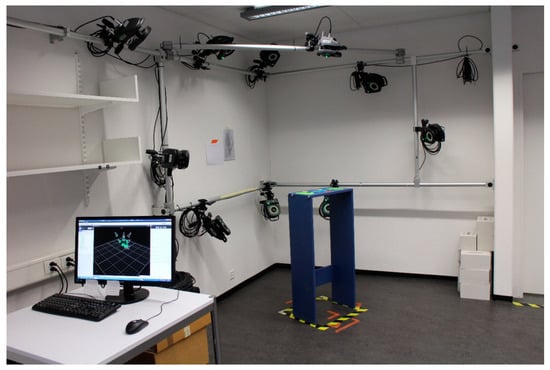
Figure 1.
Measurement system setup (VICON® MX3+ and MX3, VICON-Nexus 2.3, resolution 659 × 493 pixel, 100 Hz). The captured volume of approximately 50 × 50 × 50 cm3 was arranged in a way such that the area above the measurement table, of a height of 105 cm, could be optimally recorded.
To investigate the repeatability, each subject was measured twice on two different days. This protocol was chosen because it is relevant in the clinical context, e.g., in pre- and postoperative comparisons. In both sessions, the markers were attached by the same examiner and pictures of the hand were taken in order to facilitate repeatable placement of the markers in the following measurement session.
2.2. Movement Tasks
The measurement started with a static recording, displayed in Figure 2a, to define the neutral reference joint position. It was executed in a seated position so that the shoulder was at the same height as the elbow when placing the forearm flat on the testing table. The elbow was kept in 90° of flexion and a 40°-angled wedge was enclosed by the thumb and index finger, to ensure a consistent thumb position relative to the hand. A set of functional, isolated movement tasks for the forearm, wrist, thumb and the fingers was then performed, aiming to measure the maximal ROM, as shown in Figure 2b–i.
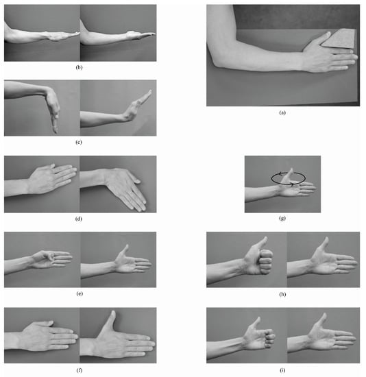
Figure 2.
Illustration of the movements for the estimation of the functional wrist and thumb joint centers and axes and the maximum range of motion: (a) static reference position; (b) forearm pronation-supination; (c) wrist flexion-extension; (d) wrist radial-ulnar deviation; (e) thumb flexion-extension (involving IP, MCP and TMC joints); (f) thumb adduction-abduction; (g) thumb circumduction; (h) full finger flexion-extension; (i) distal finger flexion-extension; (involving only PIP and DIP joints) (b,c,e,g,h,i) were performed in a standing position without a table keeping the arm close to the body and the elbow flexed at 90°; (a,d,f) were performed seated with the hand and forearm placed flat on the table.
Each movement task was started from and ended in a position according to the neutral reference joint position. After verbal and visual instruction, the subject was asked to perform a few attempts before starting the recording, whereby an isolated movement of the joint of interest was crucial. Five valid recordings were taken, with each trial consisting of three motion cycles.
2.3. Marker Placement
The marker set consisted of 46 markers with a diameter of 9, 5 and 3 mm on the elbow, forearm and wrist and fingers, respectively. Marker attachment was performed while having the subject’s forearm and hand with palm facing down on a table. The wrist was kept in a neutral position and fingers slightly spread apart. The marker positions, as shown in Table 1 and Figure 3, were chosen based on the following criteria:

Table 1.
Name and Location of the Markers.
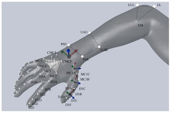
Figure 3.
Orientation of the thumb and wrist joint coordinate systems with respect to the marker positions. Dashed lines connect the markers of a segment. Anatomical frames were chosen to be right-handed orthogonal coordinate systems and showed the following sign conventions: I and i were ulnar oriented (green), J and j were dorsally oriented (blue), K and k were proximally oriented (red). A vector representing the proximal phalanx (vProx2-5) was projected onto the respective hand planes, to obtain the joint angles of the MCP2-5. The corresponding flexion plane was determined through a normal vector, which was defined by the cross product of a dorsally pointing palm normal vector (digit 2 and 3: n1; digit 4: n2; digit 5: n3) and vRef, a vector between the markers D3A and D3B in the reference position.
- Freedom in movement performance,
- Simplicity of marker position identification,
- Possibility to measure all finger and hand joints simultaneously,
- Visibility by at least two cameras during the entire movement,
- Small number of markers still allowing an analysis of all relevant degrees of freedom (DOF), and
- Application for simple and complex movements possible.
As a result of the variability in finger marker placement, two different versions of reduced finger marker sets (FM1 and FM2) were compared (see Section 2.6).
2.4. Biomechanical Model
The biomechanical hand model suggested in this protocol is divided into 18 segments, which resulted in an analysis of 17 joints, each with one to three DOF, as detailed in Table 2. Segments were considered as rigid bodies. The kinematic evaluation of the radio-ulnar joint, the wrist joint and the thumb joints was based on marker clusters. For this segmental approach, the position and orientation of each segment during the dynamic trials were determined relative to the static reference position using a least-squares fit of the corresponding marker cluster [17]. Joint rotations were then described as the relative rotation matrix of the distal segment with respect to the proximal segment. The rotation matrix was further decomposed to obtain clinically interpretable rotational components. In contrast, a vector-based approach was used to compute the finger joint angles. The selected kinematic approach, as shown in Table 2 and Figure 3, differed to the other joints because reduced marker sets do not allow the orientation of the finger segments to be fully determined in 3D space.
Table 2.
Joints of Interest and Kinematic Model.
2.4.1. Finger joints (MCP, PIP, and DIP)
Assuming only one DOF in the PIP and DIP joints (flexion-extension), the finger joint angles were calculated by means of vectors between the markers of each finger segment. The sign of the angle was determined relative to a vector pointing radially from MCP5 to MCP2, so that flexion was positive (+) and extension negative (−) [8]. The kinematics of the MCP2-5 joints was calculated by projecting a vector representing the proximal phalanx (vProx2-5) and a distally pointing reference vector (vRef) onto the respective hand planes [18], as shown in Figure 3.
2.4.2. Wrist and Thumb Joints (TMC, MCP, and IP)
The kinematic evaluation of the wrist and thumb joints was performed according to Grood and Suntay [19], whereby the first and third axes were embedded in the proximal and distal segment, respectively, and the second, so called floating axis, was perpendicular to the other two. The sequence of the JCS were compliant with the recommendations of the International Society of Biomechanics (ISB) [20], but the directions of the anatomical frames were defined based on a functional or combined functional and marker based approach [21] instead of anatomical landmarks, as presented in Table 3.
Table 3.
Equations used for the segmental and joint coordinate systems.
2.4.3. Radio-Ulnar Joint
The pronation-supination angle was analyzed using a helical axis approach [22]. The attitude vector of the proximal forearm segment relative to the segment represented by the distal forearm markers (elbow) was calculated and decomposed along the longitudinal axis of the forearm to derive the pronation-supination movement [22].
2.5. Repeatability of the Maximum Range of Motion
Because of the importance of the maximal joint mobility as a measure of hand function in a clinical setting, a validation of the method has been performed by testing the repeatability of the acquired maximal joint angle (MAX) and the ROM. As recommended by de Vet et al. [23], agreement parameters were analyzed. They express measurement error in the same unit as the original value and are not influenced by variability among the sample [24], therefore facilitating clinical interpretation.
The measurement error is represented by the standard error of measurement (SEM), which is proportional to the standard deviation of the difference (SDD) between two measurements [23]:
The minimal detectable difference (MDD) is based on the measurement error and defined as follows [23,25]:
The hypothesis that the change in the mean MAX or ROM of a joint between the two testing equals zero was analyzed with a paired t test. The SEM and MDD were calculated for each joint and DOF. According to McGinley et al. [26], errors of 2–5° are likely to be considered as reasonable for clinical applications.
2.6. Comparison FM1 vs. FM2
For the evaluation of the finger marker set, the results of two different studies within the same lab and setup were compared, with the location of the markers being the only methodological difference. The finger joint ROM of the group described above (see Section 2.1) were compared to a previous, unpublished study (conducted in 2012) that applied FM1 on a similar population of eleven healthy subjects (eight male, three female; age: 27.1 (SD 2.4), height: 176.0 cm (SD 12.0 cm), hand length: 177.1 mm (SD 11.6 mm), KEK-ZH-Nr: StV 9-2008). SEM of the finger joint ROMs were compared between the two different marker sets.
3. Results
3.1. Comparison FM1 vs. FM2
Overall, the SEM was 5.1° (SD 1.9°) and 3.7° (SD 0.7°) for the marker set with one and two markers per segment, respectively, calculated over all subjects and finger joints. The SEM for each joint is compared between the two methods in Figure 4. The error exceeded 5°, which is set to be the limit for clinical relevance, in seven out of twelve joints for FM1 and only in the MCP5 for FM2.
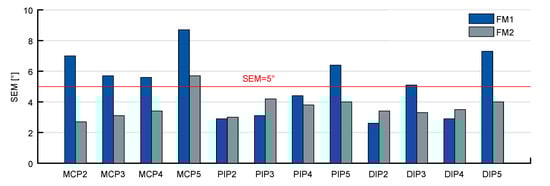
Figure 4.
SEM for the ROM in flexion of the finger joints over all subjects for FM1 and FM2. The number of analyzed subjects was different between the two studies (FM1: n = 11; FM2: n = 20).
3.2. Repeatability of the Maximum Range of Motion
All recorded data was visually inspected after joint angle calculation. Abnormal results were excluded for further data analysis in case of clearly identifiable sources of error. These were mostly missing or occluded markers crucial for joint angle calculations. A misplaced thumb marker was identified in two different cases, once by reassessing the photograph of the marker set and in another case by a marker shift becoming identifiable during data processing.
The mean difference of the analyzed joint angles ranged from −3° to 2.7° when comparing testing days (positive: higher values in the first measurement; negative: higher values in the second measurement). The p-values of the paired t test ranged from 0.53 to 0.997, reflecting that there was no statistically significant difference (p < 0.05) between test and retest in all joints.
The estimated measurement error exceeded the limit of 5° for the flexion-extension ROM of the MCP5 and all thumb joints as well as for the maximum extension angle of the MCP1 and IP (Figure 5).
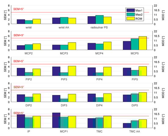
Figure 5.
SEM (left scale) and the MDD (right scale) for the maximal angles and ROM. AA = adduction (Max1)-abduction (Max2); PS = pronation (Max1)-supination (Max2); all other: flexion (Max1)-extension (Max2). Data sets included n = 20; exceptions for MCP1: n = 19, MCP4: n = 19, MCP5: n = 18, DIP5: n = 19, TMC: n = 19, and radioulnar PS: n = 16.
4. Discussion
The importance of ROM measurement in a clinical setting and its influence on diagnosis and treatment of hand pathologies demand an objective, reliable and qualitative measurement procedure. Due to the lack of such an approach for all hand and finger joints simultaneously, this study presents an elaborate description of a new motion analysis protocol and its repeatability in a clinical setting. It applies a functional approach for JCS determination, represents the thumb with a 3D kinematic approach and provides the SEM and MDD values for the maximal joint angles of 19 different DOFs of the hand. Within-subject differences of the ROM are commonly measured to evaluate the outcome and effectiveness of treatment or to monitor changes in a patient’s status over time. So far, there is no data on the repeatability of the ROM for other motion analysis protocols. Therefore, the results of this study provide unique information for data interpretation when using the presented method.
4.1. Comparison FM1 vs. FM2
Two reduced marker concepts for the fingers, which both allow the analysis of one DOF in the PIP and DIP joints, and two DOFs in the MCP joints, were compared comprising the same mathematical procedure for the calculation of the joint angles. Flexion-extension movements are of greatest clinical importance and represent the major motion plane to be assessed [12]. From this point of view, a reduced marker set is suitable to measure the most relevant joint angles, even though rotations around other axes might occur. Overall, the measurements of the ROM with two markers per segment (FM2) have proven to be more repeatable than with one marker on the joint (FM1). Still, in four joints, namely PIP2, PIP3, DIP2, DIP4, the SEM value of FM1 was smaller than the SEM of FM2. These four joints correspond to the joints with the lowest SEM values when comparing within FM1. In addition to the lower average SEM, however, the SEM values of FM2 are generally more similar among all joints (SD 0.7°), whereas the SEM values of FM1 show a larger dispersion (SD 1.9°). Skin movement artefacts affect measurement quality, especially when markers are located on the joint heads [10], a region known to be highly susceptible to skin displacement. The displacement of the skin also depends on the joint angle [27], leading to an ambiguous identification of the marker position on the joint in FM1. Therefore, the placement of markers on the segments (FM2) seemed to be clearer and more straight forward. Interestingly, it was observed in a previous study that the accuracy of finger flexion angles with FM1 could benefit from skin movements during flexion [28], whereas the effects of systematic soft tissue displacement [27,28] for joint angles of FM2 are still unknown. As shown in this study, the choice of marker positioning, considering skin movement in particular, has a big impact on the repeatability of the resulting kinematics. A limitation of this study is seen in that the comparison between the two finger marker sets was carried out on two different groups and group sizes of healthy volunteers. The resulting variation needs to be considered when interpreting these results and further investigation on the difference between these two marker sets is still needed.
Complementary to a previous study, showing that joint angles derived from FM2 are more similar to FM3 compared to measurements with FM1 [10], we found that FM2 outperforms FM1 in ROM repeatability. Hence, our results strongly support the recommendation to prefer two markers per segment (FM2) over FM1, if a reduced marker concept has to be applied. It represents a good compromise between the visibility of the markers and accuracy and it has already been successfully applied in measurements of more complex functional tasks [29].
4.2. Repeatability of the Maximal Joint Angles and the ROM
A paired t test revealed no statistically significant difference of the mean values of the maximal joint angles and the ROM between test and retest. It supports the assumption that in a healthy population no change in maximal joint mobility occurs within the two testing days. Therefore, the precision of the presented protocol can be estimated from the obtained individual test–retest differences. It comprises the positional error of the measurement system as well as errors associated with the protocol and the measured sample. To quantify the effect size of each individual factor of the error, however, further validation would be needed. Furthermore, the alignment of the JCS seems to account for another big influence on the kinematic output and different approaches lead to different joint angles [4]. A detailed analysis of the JCS alignment applied in this paper is planned in an upcoming study.
In general, good data quality can be obtained using a hand-specific camera setup. Nevertheless, as a result of the complexity of hand measurements, some data had to be excluded, which explains the different sample sizes in Figure 5.
The presented repeatability measures (Figure 5) are specific to the applied protocol and cannot be generally transferred to other approaches but rather serve as a reference for comparisons of different protocols. The value range that can be expected if a single testing is repeated by the same rater is provided by the SEM (intra-rater), whereas the MDD reflects a measure of the difference between repeated testing by taking the measurement error of both sessions into account. Hereby, only changes bigger than the variability induced by the method can be regarded as real changes [25]. In this context, only subjects whose difference on repeated testing is at least equal to or greater than the MDD reflects a real difference at a 95% confidence interval [25]. Both SEM and MDD are independent of the variation within the measured sample [23,24] and are therefore directly applicable to patients with various pathologies and restricted mobility.
The measurement of the thumb and its repeatability have been shown to be remarkably challenging, which might be explained by the complexity of thumb kinematics based on its unique kinematic and anatomical characteristics compared to the other four digits [30]. Furthermore, the measurement of the joints of the fingers closer to the thumb tended to be more repeatable, which might possibly be explained by the bigger segment size and finger coordination due to involvement in various grip types. In a recent systematic review, it was revealed that only reduced marker sets have been used to measure the thumb during daily activities of the hand so far [5], which may, however, result in a poor representation of the complex 3D movements of the thumb. Our kinematic model allows the analysis of three DOFs for each thumb joint. With regard to functional assessments, this is a clear advantage of the presented method.
Due to differences in methodology, a comparison to previous studies analyzing the repeatability of hand motion analysis protocols is limited. Our study was the only one using maximum joint angles during dynamic motion tasks to assess the test–retest difference, whereas all other studies focused on static postures defined by casts [31], metallic frames [8] or gripping of specific objects [11,13].
On the level of individual joints, the error was slightly smaller for the wrist, MCP2 and MCP3 joints than previously reported [8,31]. Averaged over all hand joints, the repeatability (MDD 8.8°/RMSE 4.7°) lies in a similar range as previously published (MDD 5.5–10.5°/RMSE 3.4) [11,13], but with the above-mentioned difficulties for the measurement of the thumb and the small finger. As the variability in the execution of the task might differ between ROM and static postures, the comparison between these different studies allows no final conclusions on the influence of the marker placement or the kinematic model on the repeatability of the different approaches.
From a clinical point of view, the results of this study highlight the importance of a protocol optimization in order to minimize errors. The repeatability of ROM measurement needs to be precise enough to detect a difference that is relevant in a patient’s hand function and, therefore, allows an accurate judgment of a patient’s improvement after a treatment or therapy. Thus, the MDD of a testing protocol should be smaller than the clinically relevant difference to be detected.
In gait analysis, joint angle errors up to 5° have been shown to be generally accepted [26]. A corresponding value in hand kinematics is currently not available. Based on the high mobility in the hand joints and the significant restrictions to be expected due to injuries or pathologies, we consider this value to be transferable to hand motion analysis. The majority of the analyzed joints within this study revealed an error below 5° (SEM 1.2–6.4°) and the averaged coefficient of variation was less than 5% of the ROM. The protocol has, hence, been shown to be suitable for test–rest analysis in a clinical setting. Despite the bigger error in the thumb and MCP5 joints, the protocol is yet appropriate for applications where large individual improvements or deviations from the norm in those joints are to be expected. A comparison of the repeatability of the motion analysis protocol with the common measurement method involving goniometers facilitates the selection of the appropriate method for future researchers interested in the change in ROM [32]. Whether the repeatability of a method is high enough needs, however, to be put in context with the intended application and might vary with regards to different objectives.
5. Conclusions
This study provides a motion analysis protocol, which allows a simultaneous kinematic analysis of all joints of the fingers and hand, with its focus lying on the repeatability of the method. Reliable protocols are required for studies that aim to detect small differences between groups as well as for longitudinal study designs with multiple testing. In general, a reduced marker concept for the fingers is applicable for more complex functional tasks, whereby the repeatability of the ROM showed a clear advantage of marker sets with two markers per segment compared to the approach with markers on the joint heads. For larger segments such as the palm, forearm and thumb, marker concentration is usually not a problem, which is why marker clusters were selected, and a more advanced kinematic analysis was possible. A functional approach is applied for the definition of the wrist and thumb JCS.
The results provide normative values of the ROM for a young, healthy population as well as an estimate of the measurement error of the method. Despite its role as one of the most important clinical outcome measures, statements on the ROM repeatability of hand and finger joints measured with previously published motion capture methods were missing completely, therefore limiting comparison between different methods. Moreover, knowledge of the magnitude of SEM and MDD has an important clinical impact, as it facilitates the selection of an appropriate measurement method. Considering the importance of the ROM for clinical evaluations of joint function, the provided error estimates are required for meaningful data interpretation and may be used for comparison with other protocols in the future. In conclusion, the comprehensive analysis of the repeatability of the presented motion analysis protocol can be transferred to future studies in patients, such as comparisons between different treatment regimens or evaluation of pre–postoperative improvement.
Author Contributions
Conceptualization, M.C.; methodology, D.J., G.F. and L.R.; software, D.J. and G.F.; validation, G.F and D.J.; formal analysis, G.F and D.J.; investigation, D.J., L.R. and G.F.; resources, M.C.; data curation, D.J., L.R., and G.F.; writing—original draft preparation, D.J. and G.F.; writing—review and editing, R.L.; visualization, D.J. and G.F.; supervision, M.C. and R.L.; project administration, L.R.; funding acquisition, M.C. All authors have read and agreed to the published version of the manuscript.
Funding
Publication cost was covered by the ETH Zurich.
Acknowledgments
We would like to thank Christopher Richards from the University of Wollongong, Australia, for drawing Figure 3 and Eva Lanter and Michael Plüss from the ETH Zurich, Switzerland, for their technical help in formatting the figures.
Conflicts of Interest
The authors declare no conflict of interest.
References
- Rau, G.; Disselhorst-Klug, C.; Schmidt, R. Movement biomechanics goes upwards: From the leg to the arm. J. Biomech. 2000, 33, 1207–1216. [Google Scholar] [CrossRef]
- Murgia, A.; Kyberd, P.; Chappell, P.; Light, C. Marker placement to describe the wrist movement during activities of daily living in cyclical tasks. Clin. Biomech. 2004, 19, 248–254. [Google Scholar] [CrossRef] [PubMed]
- Kontaxis, A.; Cutti, A.; Johnson, G.; Veeger, H. A framework for the definition of standardized protocols for measuring upper-extremity kinematics. Clin. Biomech. 2009, 24, 246–253. [Google Scholar] [CrossRef] [PubMed]
- Goislard de Monsabert, B.; Visser, J.; Vigouroux, L.; Van der Helm, F.; Veeger, H. Comparison of three local frame definitions for the kinematic analysis of the fingers and the wrist. J. Biomech. 2014, 47, 2590–2597. [Google Scholar] [CrossRef] [PubMed]
- Reissner, L.; Fischer, G.; List, R.; Giovanoli, P.; Calcagni, M. Assessment of hand function during activities of daily living using motion tracking cameras: A systematic review. Proc. Inst. Mech. Eng. H 2019, 233, 764–783. [Google Scholar] [CrossRef]
- Cerveri, P.; De Momi, E.; Lopomo, N.; Baud-Bovy, G.; Barros, R.; Ferrigno, G. Finger kinematic modeling and real-time hand motion estimation. Ann. Biomed. Eng. 2007, 35, 1989–2002. [Google Scholar] [CrossRef]
- Anglin, C.; Wyss, U. Review of arm motion analyses. Proc. Inst. Mech. Eng. H 2000, 214, 541–555. [Google Scholar] [CrossRef]
- Metcalf, C.; Notley, S.; Chappell, P.; Burridge, J.; Yule, V. Validation and application of a computational model for wrist and hand movements using surface markers. IEEE Trans. Biomed. Eng. 2008, 55, 1199–1210. [Google Scholar] [CrossRef]
- Coupier, J.; Hamoudi, S.; Telese-Izzi, S.; Feipel, V.; Rooze, M.; Van Sint Jan, S. A novel method for in-vivo evaluation of finger kinematics including definition of healthy motion patterns. Clin. Biomech. 2016, 31, 47–58. [Google Scholar] [CrossRef]
- Lee, K.; Jung, M. Quantitative comparison of marker attachment methods for hand motion analysis. Int. J. Occup. Saf. Ergon. 2015, 21, 30–38. [Google Scholar] [CrossRef]
- Carpinella, I.; Mazzoleni, P.; Rabuffetti, M.; Thorsen, R.; Ferrarin, M. Experimental protocol for the kinematic analysis of the hand: Definition and repeatability. Gait Posture 2006, 23, 445–454. [Google Scholar] [CrossRef] [PubMed]
- Rash, G.; Belliappa, P.; Wachowiak, M.; Somia, N.; Gupta, A. A demonstration of the validity of a 3-D video motion analysis method for measuring finger flexion and extension. J. Biomech. 1999, 32, 1337–1341. [Google Scholar] [CrossRef]
- Sancho-Bru, J.; Jarque-Bou, N.; Vergara, M.; Pérez-González, A. Validity of a simple videogrammetric method to measure the movement of all hand segments for clinical purposes. Proc. Inst. Mech. Eng. H 2014, 228, 182–189. [Google Scholar] [CrossRef]
- Degeorges, R.; Parasie, J.; Mitton, D.; Imbert, N.; Goubier, J.; Lavaste, F. Three-dimensional rotations of human three-joint fingers: An optoelectronic measurement. Preliminary results. Surg. Radiol. Anat. 2005, 27, 43–50. [Google Scholar] [CrossRef] [PubMed]
- Warlow, O.M.; Lawson, S.E. A technique for motion capture of the finger using functional joint centres and the effect of calibration range of motion on its accuracy. Proc. Inst. Mech. Eng. H 2012, 226, 360–367. [Google Scholar] [CrossRef]
- Murphy, M.; Sunnerhagen, K.; Johnels, B.; Willén, C. Three-dimensional kinematic motion analysis of a daily activity drinking from a glass: A pilot study. J. Neuro Eng. Rehabil. 2006, 3. [Google Scholar] [CrossRef]
- Gander, W.; Hrebicek, J. Least squares fit of point clouds. In Solving Problems in Scientific Computing Using Maple and MATLAB®, 3rd ed.; Springer: Berlin, Germany, 1997; pp. 339–349. [Google Scholar]
- Metcalf, C.D.; Notley, S.V. Modified kinematic technique for measuring pathological hyperextension and hypermobility of the interphalangeal joints. IEEE Trans. Biomed. Eng. 2011, 58, 1224–1231. [Google Scholar] [CrossRef]
- Grood, E.; Suntay, W. A joint coordinate system for the clinical description of three-dimensional motions: Application to the knee. J. Biomech. Eng. 1983, 105, 136–144. [Google Scholar] [CrossRef]
- Wu, G.; van der Helm, F.; Veeger, H.; Makhsous, M.; van Roy, P.; Anglin, C.; Nagels, J.; Karduna, A.; McQuade, K.; Wang, X.; et al. ISB recommendation on definitions of joint coordinate systems of various joints for the reporting of human joint motion—Part II: Shoulder, elbow, wrist and hand. J. Biomech. 2005, 38, 981–992. [Google Scholar] [CrossRef] [PubMed]
- List, R.; Gulay, T.; Stoop, M.; Lorenzetti, S. Kinematics of the trunk and the lower extremities during restricted and unrestricted squats. J. Strength Cond. Res. 2013, 27, 1529–1538. [Google Scholar] [CrossRef]
- Woltring, H.J. 3-D attitude representation of human joints: A standardization proposal. J. Biomech. 1994, 27, 1399–1414. [Google Scholar] [CrossRef]
- de Vet, H.C.; Terwee, C.B.; Knol, D.L.; Bouter, L.M. When to use agreement versus reliability measures. J. Clin. Epidemiol. 2006, 59, 1033–1039. [Google Scholar] [CrossRef] [PubMed]
- Stratford, P.W.; Goldsmith, C.H. Use of the standard error as a reliability index of interest: An applied example using elbow flexor strength data. Phys. Ther. 1997, 77, 745–750. [Google Scholar] [CrossRef] [PubMed]
- Weir, J.P. Quantifying test-retest reliability using the intraclass correlation coefficient and the SEM. J. Strength Cond. Res. 2005, 19, 231–240. [Google Scholar] [PubMed]
- McGinley, J.L.; Baker, R.; Wolfe, R.; Morris, M.E. The reliability of three-dimensional kinematic gait measurements: A systematic review. Gait Posture 2009, 29, 360–369. [Google Scholar] [CrossRef]
- Ryu, J.H.; Miyata, N.; Kouchi, M.; Mochimaru, M.; Lee, K.H. Analysis of skin movement with respect to flexional bone motion using MR images of a hand. J. Biomech. 2006, 39, 844–852. [Google Scholar] [CrossRef]
- Metcalf, C.D.; Phillips, C.; Forrester, A.; Glodowski, J.; Simpson, K.; Everitt, C.; Darekar, A.; King, L.; Warwick, D.; Dickinson, A.S. Quantifying soft tissue artefacts and imaging variability in motion capture of the fingers. Ann. Biomed. Eng. 2020, 48, 1551–1561. [Google Scholar] [CrossRef]
- Woodworth, J.A.; McCullough, M.B.; Grosland, N.M.; Adams, B.D. Impact of simulated proximal interphalangeal arthrodeses of all fingers on hand function. J. Hand Surg. Am. 2006, 31, 940–946. [Google Scholar] [CrossRef]
- Zhang, X.; Braido, P.; Lee, S.-W.; Hefner, R.; Redden, M. A normative database of thumb circumduction in vivo: Center of rotation and range of motion. Hum. Factors 2005, 47, 550–561. [Google Scholar] [CrossRef]
- Speirs, A.D.; Small, C.F.; Bryant, J.T.; Pichora, D.R.; Zee, B.Y. Three-dimensional metacarpophalangeal joint kinematics using two markers on the phalanx. Proc. Inst. Mech. Eng. H 2001, 215, 415–419. [Google Scholar] [CrossRef]
- Reissner, L.; Fischer, G.; List, R.; Taylor, W.R.; Giovanoli, P.; Calcagni, M. Minimal detectable difference of the finger and wrist range of motion: Comparison of goniometry and 3D motion analysis. J. Orthop. Surg. Res. 2019, 14, 173. [Google Scholar] [CrossRef] [PubMed]


© 2020 by the authors. Licensee MDPI, Basel, Switzerland. This article is an open access article distributed under the terms and conditions of the Creative Commons Attribution (CC BY) license (http://creativecommons.org/licenses/by/4.0/).