Article

Features of Electrophoretic Deposition of a Ba-Containing Thin-Film Proton-Conducting Electrolyte on a Porous Cathode Substrate

1
Laboratory of Complex Electrophysic Investigations, Institute of Electrophysics, Ural Branch of the Russian Academy of Sciences, Yekaterinburg 620016, Russia
2
Department of Physical and Inorganic Chemistry, Institute of Natural Sciences and Mathematics, Ural Federal University, Yekaterinburg 620002, Russia
3
Laboratory of Solid Oxide Fuel Cells, Institute of High Temperature Electrochemistry, Ural Branch of the Russian Academy of Sciences, Yekaterinburg 620137, Russia
4
Laboratory of Chemical Design of New Multifunctional Materials, Institute of Natural Sciences and Mathematics, Ural Federal University, Yekaterinburg 620002, Russia
5
Laboratory of Cross-Cutting Technologies in Distributed Power Generation (InEnergy), Institute of High Temperature Electrochemistry, Ural Branch of the Russian Academy of Sciences, Yekaterinburg 620137, Russia
6
Department of Environmental Economics, Graduate School of Economics and Management, Ural Federal University, Yekaterinburg 620002, Russia
*
Authors to whom correspondence should be addressed.
Appl. Sci. 2020, 10(18), 6535; https://doi.org/10.3390/app10186535
Submission received: 18 July 2020 / Revised: 14 August 2020 / Accepted: 16 September 2020 / Published: 18 September 2020
(This article belongs to the Special Issue Proton Conducting Solid Oxide Fuel Cells)

Abstract

:

Featured Application

The results of the study can be used for the development of the production technology of cathode-supported SOFCs with a thin-film electrolyte using the electrophoretic deposition method.

Abstract

This paper presents the study of electrophoretic deposition (EPD) of a proton-conducting electrolyte of BaCe0.89Gd0.1Cu0.01O3-δ (BCGCuO) on porous cathode substrates of LaNi0.6Fe0.4O3−δ (LNFO) and La1.7Ba0.3NiO4+δ (LBNO). EPD kinetics was studied in the process of deposition of both a LBNO sublayer on the porous LNFO substrate and a BCGCuO electrolyte layer. Addition of iodine was shown to significantly increase the deposited film weight and decrease the number of EPD cycles. During the deposition on the LNFO cathode, Ba preservation in the electrolyte layer after sintering at 1450 °C was achieved only with a film thickness greater than 20 μm. The presence of a thin LBNO sublayer (10 μm) did not have a pronounced effect on the preservation of Ba in the electrolyte layer. When using the bulk LBNO cathode substrate as a Ba source, Ba was retained in a nominal amount in the BCGCuO film with a thickness of 10 μm. The film obtained on the bulk LBNO substrate, being in composition close to the nominal composition of the BCGCuO electrolyte, possessed the highest electrical conductivity among the films deposited on the various cathode substrates. The technology developed is a base step in the adaptation of the EPD method for fabrication of cathode-supported Solid Oxide Fuel Cells (SOFCs) with dense barium-containing electrolyte films while maintaining their nominal composition and functional characteristics.

1. Introduction

Electrochemical devices converting chemical energy of a fuel directly into electricity without the necessity for direct combustion as an intermediate stage are known as fuel cells. Solid oxide fuel cells are among the most promising of these, owing to their high efficiency of energy conversion and their adaptability to various kinds of hydrocarbon fuels including biofuels [1,2,3]. Fuel cells, utilizing proton conductors as electrolyte membranes (PCFS), possess some significant advantages, the most important of which relates to changes in the reactions taking place at the electrodes. Water is produced on the cathode side of the cell as a product of the reactions, thus enabling a more efficient fuel use. The open circuit voltage is maintained at a high level and there is no problem with reduced anode stability [1].
A recent trend in the development of solid oxide fuel cells is the practice of lowering the working temperature down to 550–700 °C in order to increase the long-term stability and broaden the choice of cheap functional materials applicable for the cells’ production. The cells’ performance is strongly dictated by the ohmic loss of the electrolyte and resistance due to the electrodes’ polarization. Thus, effective operation at decreased temperatures requires the application of materials with advanced electrical properties and the development of cost-effective and versatile methods for the formation of cells’ structures with reduced electrolyte thickness and improved electrode microstructure [4].
Solid state solutions based on BaCeO3 are promising electrolyte materials for SOFCs due to their high co-ionic (oxygen-ion and proton) conductivity and low activation energy in the intermediate temperature range and in a humidified atmosphere [5,6,7]. Gd-doped BaCeO3 exhibits one of the highest levels of ionic conductivity at temperatures below 800 °C among the electrolytes stable in a fuel cell environment [8,9,10]. There are several techniques for depositing thin electrolyte films on porous and dense substrates, including chemical vapor deposition, electrochemical vapor deposition, ceramic and colloidal processes, and various sputtering processes using ion beam, magnetron, electron beam, and others [11,12]. Among them there are several studies on the formation of Gd-doped BaCeO3-based films; however, deposition was performed mainly on anode substrates using dip-coating [13], spray pyrolysis [14], and tape calendering [7].
Recently, our group has presented several studies on electrophoretic deposition (EPD) of BaCeO3-based films on dense cathode substrates [15,16]. The EPD process is carried out on the electrodes immersed in a suspension of ceramic particles, between which a potential difference is set. The particles in a liquid medium are solvated, and an electric charge arises on them, thereby, on the one hand, the particles and their aggregates move under the action of an external electric field; on the other hand, the particles are deposited on the electrode and a deposit of the solvated particles is formed. Following the formation of the deposit, drying and sintering stages are carried out to finally form a coating [17]. EPD offers such advantages in deposition of thin-film electrolytes for SOFCs’ applications as inexpensive equipment, short deposition time, simplicity of process management via current/voltage adjustment, and adaptability to the electrolyte composition and substrate shape [12,18,19]. The main problem, which appears during sintering Ba-containing thin films, consists of Ba loss at high temperatures due to evaporation and chemical interaction with the electrode substrate. Ba volatility is a well-known fact for BaCeO3- and BaZrO3-based electrolytes. Ba loss leads to redistribution of the acceptor dopant, occupying the B-position, on both A- and B-sublattices, which results in a decrease in a reduced concentration of oxygen vacancies responsible for co-ionic transport and causes violation of the electrical properties, segregation of secondary phases on the grain boundaries, degradation of the mechanical properties, and even electrolyte decomposition [20]. Ba evaporation becomes even more pronounced in the case of thin films. The problem of redistribution and barium depletion in BaCeO3-based films with a thickness of less than 10 microns was considered in a number of studies where various strategies were proposed to prevent cation disbalance in the sintered films, for example, sintering a film in a powder of the same composition or BaCeO3 [21] or application of a protective BaCeO3 layer on the top of the film before its sintering [22]. In [16], a study was conducted of the methods for forming a thin-film electrolyte BaCe0.89Gd0.1Cu0.01O3-δ (BCGCuO) on dense model substrates La2NiO4+δ (LNO) and La1.7Ba0.3NiO4+δ (LBNO) by the EPD method. In particular, a BCGCuO film was deposited on a LNO substrate and a half-cell was sintered in the BCGCuO powder; a BCGCuO film was deposited on a LNO substrate and a BaCeO3 protective film was deposited on the top of the BCGCuO film and co-sintered; the BCGCuO film was deposited on a LBNO substrate followed by sintering. The Ba loss observed in both BCGCuO films deposited on the LNO substrate was mainly due to the diffusion of barium into the substrate, thus the use of protective BaCeO3 film was ineffective. At the same time, the Ba content was nominal in the BCGGuO film deposited and sintered on the LBNO substrate without additional protective measures. It was supposed that the LBNO substrate may play a role of a source of Ba, compensating its evaporation during the sintering.
In this study, in order to further develop EPD technology for the formation of a thin-film proton-conducting BCGCuO electrolyte, its deposition was performed on porous cathode substrates: LaNi0.6Fe0.4O3−δ (LNFO) substrates, fabricated from the powders obtained by solid state reaction and Pechini methods, on LBNO substrates fabricated from the solid state reaction powder, and bi-layered LNFO/LBNO cathode substrates, where the LBNO cathode sublayer was deposited by the EPD method form the suspension, prepared from the citrate-nitrate powder, on the top of porous LNFO substrates. The aim of the study was to maintain the nominal barium content in the BCGCuO electrolyte film during sintering to ensure the required conductivity characteristics along with preservation of the porous structure of the substrates. The use of cathode material LNFO with high electronic conductivity (~700 S/cm at 700 °C) as a cathode collector can increase cell performance [23,24]. In addition, LNFO possesses a moderate value of the thermal expansion coefficient (TEC) of 12.5 × 10⁻⁶ K−1 in the temperature range 50–900 °C. While the use of LBNO material as a functional cathode layer directly in contact with a proton-conducting electrolyte will not only reduce mutual chemical interaction of the materials, it will also increase electrochemical activity [25]. A basic investigation of the bilayer porous substrates for the deposition of oxygen ion-conducting electrolytes and conditions to preserve the supporting cathode structure during electrolyte film sintering was presented in [26,27]. The results were adopted for use in this study, taking into account the features of the Ba-containing electrolyte. The technology developed makes it possible to determine further directions in the EPD application for producing cathode-supported SOFCs with proton-conducting electrolytes.

2. Materials and Methods

2.1. Synthesis and Characterization of the Electrolyte and Electrode Materials

To obtain porous substrates and different functional layers, the electrolyte and electrode materials were synthesized using various techniques. Synthesis of the BCGCuO electrolyte material used for the suspension preparation and film formation was carried out using a nitrate combustion method. BaCO3 (98.4% purity, Vekton, Russia), Gd(NO3)3∙6H2O (99%, Reaktiv, Russia), Ce(NO3)3·6H2O (99%, Reaktiv, Russia), and CuO (99%, Reakhim, Russia) were used as raw materials; glycine and citric acid were used as a fuel and oxidizer, respectively. The details of the synthesis procedure are given elsewhere [16]. Following the final synthesis stage at 1050 °C (10 h), the BCGCuO powder was grinded for 2 h in a Pulverisette 6 planetary mill (Fritsch, Germany) in a Teflon drum with tetragonal ZrO2-Y2O3 milling bodies in an isopropyl alcohol medium (weight ratio of 1:5:1).
Synthesis of the LNFO electrode material for the cathode substrate was carried out using a modified Pechini method (designated as LNFOP). La(NO3)3·6H2O (99%, Ural warehouse of chemicals, Russia), Fe(NO3)3·9H2O (99%, Reaktivtorg, Russia), and Ni(NO3)2·6H2O (99%, Reaktiv, Russia) were dissolved in distilled water, thoroughly mixed, and then, organic fuels such as citric acid and ethylene glycol were added. The obtained mixture was heated, evaporated, and decomposed at 450 °C. The obtained black ash was calcinated at 900 °C (8 h) and 1180 °C (8 h) with intermediate and final milling in the planetary mill in an agate drum with stainless-steel milling bodies in an isopropyl alcohol medium (weight ratio of 1:5:1).
A nitrate combustion method was applied to prepare the LBNO powder (designated as LBNOnc) for the suspension preparation and EPD formation of the electrode functional sublayer on the top of porous LNFO substrates. The starting materials of La(NO3)3·6H2O (99%, Ural warehouse of chemicals, Russia), Ni(NO3)2·6H2O (99%, Reaktiv, Russia), and Ba(NO3)2 (99.9%, Vekton, Russia) were completely dissolved in distilled water and citric acid was added as a chelating agent (metal cations/citric acid mole ratio of 1:2). The pH value of the mixture equal to 8 was adjusted by addition of a 10% NH4OH solution. Then, the solution was heated up to 200 °C with consecutive evaporation, gelation, and combustion. The as-prepared powder was grinded and calcinated at 700 °C to remove residual organics. The obtained powder was ball-milled (1 h) with the following synthesis at 1100 °C (5 h). To obtain a fine powder for the suspension preparation, after the final step of the synthesis, the LBNOnc powder was milled for 1 h.
The LBNO and LNFO materials for the cathode substrates were obtained via a two-stage solid state reaction method (designated as LBNOss and LNFOss, respectively). The initial components La2O3 (99.99%, Vekton, Russia), NiO (99%, Vekton, Russia), BaCO3 (99%, Vekton, Russia), and Fe2O3 (99%, Ormet, Russia) were taken in stoichiometric amounts, mixed and grinded in the planetary mill (1 h), and calcinated step-by-step at 1150 °C (2 h) and 1250 °C (5 h) with intermediate ball-milling (1 h). Following the final synthesis step, the powders were ball-milled for 1 h.
The obtained powders were subjected to X-ray phase analysis via a D/MAX-2200 diffractometer (Rigaku, Japan) using CuKα radiation in an angle range of 20° ≤ 2θ ≤ 80°. The phase composition and crystal structure identification and calculation of the cell parameters was accomplished by employing the JCPDS base using MDI Jade 6 software. The XRD patterns are presented in the Supplementary Materials Figures S1–S5.
The powders’ specific surface area (SBET) was determined after the final ball-milling using a TriStar 3000 device (Micromeritics, Germany). The characterization results are given in Table 1.
The BCGCuO powder chemical composition was determined by an inductively coupled plasma optical emission spectroscopy by means of an Optima 4300 DV device (PerkinElmer, Boston, MA, USA) and was close to the nominal composition, namely: Ba-20.51, Ce-18.32, Gd-1.80, Cu-0.15 at.%.

2.2. Porous Cathode Substrates’ Preparation and Characterization

For the deposition, porous cathode substrates based on LNFOss, LNFOp, and LBNOss electrode materials with the addition of a graphite pore former were prepared. The materials were mixed with the pore-former taken in an amount of 20 wt.% in the mill in an isopropyl alcohol medium (0.5 h), dried and compacted by a uniaxial semidry pressing with the addition of a polyvinyl butyral binder at 6 MPa, followed by sintering at 1400 °C, 2 h (heating/cooling rate of 100 °/h). The density of the compact samples, ρ, was calculated from their weight and geometrical dimensions. Total porosity, P, was calculated according to the formula P = 100 − ρrel%, where ρrel = ρ/ρcr 100% (ρcr is the crystallographic density of the sample calculated from the XRD data). The calculated porosity of the sintered substrates was in the range of 48–50%, 26–27%, and 24–28% for LNFOss, LNFOp, and LBNOss, respectively. Before being used in the EPD process, the substrates were first polished and cleaned in an ultrasonic bath. Then, they were annealed at 900 °C for 1 h.

2.3. Preparation of Suspensions Based on the Electrode and Electrolyte Powders and Their Characterization

A suspension for the EPD of the functional electrode layer was prepared using the LBNOnc powder (concentration 10 g/L) in isopropanol (special purity grade, Component-Reaktiv, Russia) with the addition of a solution of 0.4 g/L molecular iodine in acetylacetone (analytically pure grade, Merck, CAS 123-54-6). Molecular iodine was added to the suspension as a charge agent. This contributed to the formation of a positive charge on the particles by increasing the current strength during deposition and therefore, increasing the deposition efficiency [17,28]. The concentration of iodine was chosen according to the experimental data presented in [29,30].
Suspensions on the base of BCGCuO powder were prepared in a mixed dispersion medium isopropanol/acetylacetone (70/30 vol. ratio). Suspensions of 1 and 10 g/L concentrations were prepared by mixing the components and sonication using an ultrasonic bath UZV-13/150-TH (Reltec, Russia) for 5–125 min. Molecular iodine was also used to improve the BCGCuO suspension’ properties.

2.4. Electrophoretic Deposition of the Films and Their Characterization

Electrophoretic deposition was performed on a specialized computerized installation (IEP UB RAS, Russia) providing constant current or constant voltage modes. In the EPD cell, the cathode substrates (LNFOss, LNFOp, or LBNOss) with an effective area of 113 mm2 served as a cathode, while a stainless-steel disk with the same dimensions served as an anode. There was a separation of 1 cm between electrodes.
Examination of the deposited film’s microstructure was carried out with the use of a field-emission electron microscope Mira 3 LMU (Tescan, Czech Republic) supplied with an INCA Energy 350 energy-dispersive X-ray (EDX) microanalysis system and an X-max 80 energy dispersive spectrometer (Oxford Instruments, UK). SEM images in BSE (back-scattered electrons) and SE (secondary electrons) modes were obtained at a high voltage of 10 kV and beam intensity of 10 a.u. For the EDX analysis, the high voltage of 20 kV and a beam intensity of 15 a.u. were used.

2.5. Conductivity Measurements

The conductivity of the BCGCuO electrolyte film deposited on the cathode substrates was measured by an ac two-probe method. To fabricate electrochemical cells for the measurements, platinum electrodes with an effective surface area of approximately 0.12 cm2 were deposited by painting on both sides of the half-cell, comprising the porous cathode substrate and deposited film, and sintered at 1000 °C, 1 h. A potentiostat SI 1260 with an electrochemical interface SI 1287 (Solartron Analytical, Hampshire, UK) was used to perform electrochemical measurements on the obtained cells by an impedance spectroscopy method in a frequency range of 0.01 Hz–1 MHz with an amplitude of applied voltage of 30 mV. Measurements were performed in the temperature range of 550–750 °C in dry and wet air (pH2O ~ 1 × 10⁻³ and 5 × 10⁻² atm, respectively). The resistance of the electrolyte film was determined from the analysis of the impedance spectra using Zview v. 2.8 software.

3. Results and Discussion

3.1. Formation of the LBNOnc Functional Layer on the Porous LNFOss and LNFOP Cathode Substrates by the EPD Method

The optimal modes of deposition of the LBNOnc film from the suspension of micropowder with a concentration of 10 g/L in isopropanol with the addition of iodine (0.4 g/L) were determined by the test deposition on a Ni-foil. For deposition of the green LBNOnc coatings with a thickness of approximately 10 μm, the deposition voltage varied from 20 to 100 V and the deposition time from 1 to 5 min. Other criteria for choosing the deposition mode were the deposition weight, film uniformity, and the absence of cracks on the film surface. Current–voltage characteristics (CVC) obtained during the test deposition and the dependence of the current strength on time at the voltage value of 100 V are presented in Figure 1. The current strength linearly depends on the voltage in the range of measurements (12–150 V) i.e., the EPD cell resistance does not depend on the voltage in this range (Figure 1a). In the study of this suspension, nonlinearity and hysteresis of the I–V characteristics were not found. The linear character of the I–V characteristics corresponds to the constant electrophoretic mobility of particles in the suspension.
When conducting the test deposition at a constant voltage, the current strength in the time interval from 0 to 15 min is characterized by chaotic fluctuations (approximately within 10% of the average value) with a general growth trend (Figure 1b). It is likely that the processes of increasing the resistance of the deposited film and depletion of the suspension do not have a significant effect on the kinetics of the current change during the EPD process, which may be due to the effect of ionic charge transfer in the suspension with the participation of free protons under the influence of an external electric field [31,32].
It is worth noting that deposition from the LBNOnc suspension without iodine did not occur. The addition of iodine leads to the additional generation of protons in the suspension due to its reaction with acetylacetone, which changes the charge state of the particles and the conductivity of the suspension [29]. According to the experimental data obtained on a Ni-foil, to form a layer with a thickness of 10 μm, it is necessary that the weight of the deposited film is about 8–10 mg/cm2 with respect to the geometric surface of the electrode, which is realized in the case of a constant voltage of 100 V and a deposition time of 2 min. EPD of the LBNOnc electrode material on porous substrates of LNFOp and LNFOss was performed in one step at a constant voltage of 100 V and a deposition time of 2 min, while the current strength was 6.92 and 6.00 mA, respectively. After deposition, the LBNOnc coatings were dried in a Petri dish. The weight of green dried LBNOnc coatings at the LNFOp and LNFOss cathode substrates was 8.1 and 3.5 mg/cm2, respectively. The deposition weight of the film obtained on the LNFOp substrate is in good agreement with that obtained in the test deposition. A decrease in the weight of the green dried coatings in the case of LNFOss may be caused by its lower conductivity due to higher porosity [24]. After drying, the functional LBNOnc layers deposited on the LNFOp and LNFOss cathode substrates were sintered at 1350 °C, 1 h. The rate of heating and cooling was 1 °C/min.

3.2. Determination of the Optimal Deposition Mode of the BCGCuO Electrolyte Film (Test Deposition)

EPD of BCGCuO films with a thickness of approximately 6 μm on a model dense LBNOss cathode in our earlier study [16] was carried out by multiple deposition/sintering cycles (12 cycles). The suspension in this case was subjected to ultrasonic treatment (UST), followed by centrifugation and removal of aggregates larger than 1 μm. A BMMA-5 modifier (a co-polymer of butyl methacrylate containing 5 mol.% of methacrylic acid) was added to the de-aggregated suspension (fractional composition of the suspension: aggregates of 323 (10) nm (81%) and individual particles of 60 (2) nm (19%)) to prevent coating cracking during drying, which is typical for submicron particles’ layers. One of the objectives of this work was to reduce the number of deposition/sintering cycles. Therefore, the deposition of the BCGCuO powder in the present study was performed from the BCGCuO suspension after UST for 125 min (fractional composition in suspension: small aggregates 370 (11) nm in size—19% and large aggregates 1639 (49) nm—81%) without centrifuging and adding the BMMA-5 modifier to avoid the insulating effect of the polymer adsorbed on the particles. The suspension without the centrifugation treatment was used for the EPD to maintain the suspension concentration at the given level and thus, increase the deposition rate and reduce the number of deposition/sintering cycles. Additionally, molecular iodine was used to increase the deposition efficiency.
The optimal deposition mode was determined according to the results of the test deposition on the Ni-foil from a suspension with a concentration of 10 g/L of the BCGCuO micropowder in a mixed dispersion medium of isopropanol/acetylacetone (70/30 vol.%). Figure 2 shows the experimental time dependencies of the deposition weight during the EPD performed at a constant voltage of 80 V from the BCGCuO suspensions without (1) and with (2) the addition of molecular iodine in the amount of 0.4 g/L. It is seen that the addition of iodine significantly increases the deposition weight of the BCGCuO electrolyte and the dependence of the deposition weight on time when using a modified suspension has a pronounced nonlinear character.
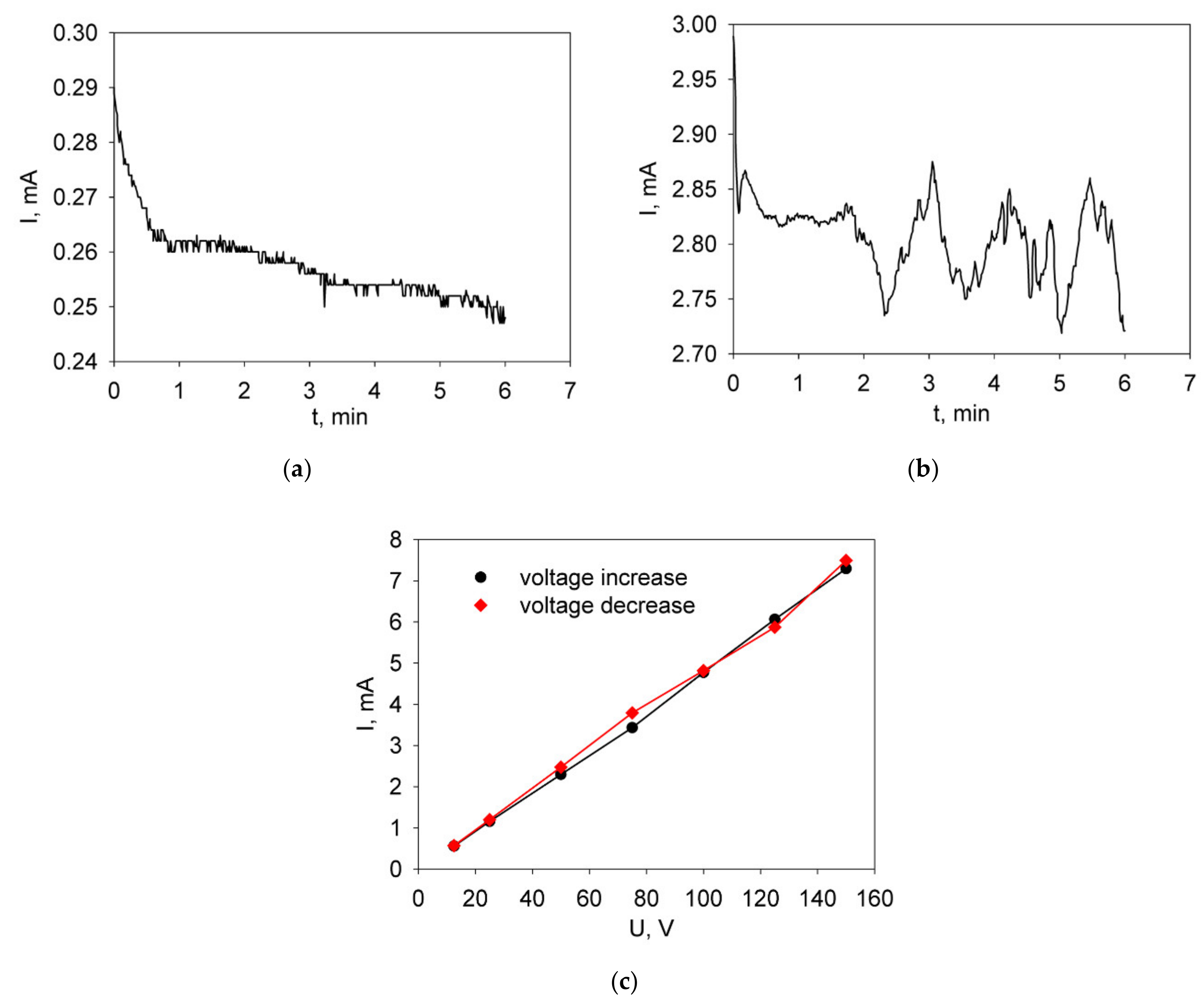
Time dependencies of the current strength at a constant voltage of 80 V during EPD from the base BCGCuO suspension and from that modified by the addition of iodine are shown in Figure 3a,b, respectively. For the base suspension without additive, there was a clear tendency for the current strength to decrease with time. In addition, the greatest rate of reduction was observed during the first minute of the deposition. For the modified suspension, there was no tendency to drop or increase current strength, but random fluctuations occurred around the average value and the current strength was much higher (approx. 1 order of magnitude) compared to that of the base suspension. The current dependence for the BCGCuO suspension with the addition of iodine demonstrated significant chaotic oscillations, the nature of which is probably associated with a change in the charge state of particles in suspensions. The I–V characteristic obtained for the modified suspension was characterized by insignificant nonlinearity and hysteresis when increasing and decreasing the cell voltage.
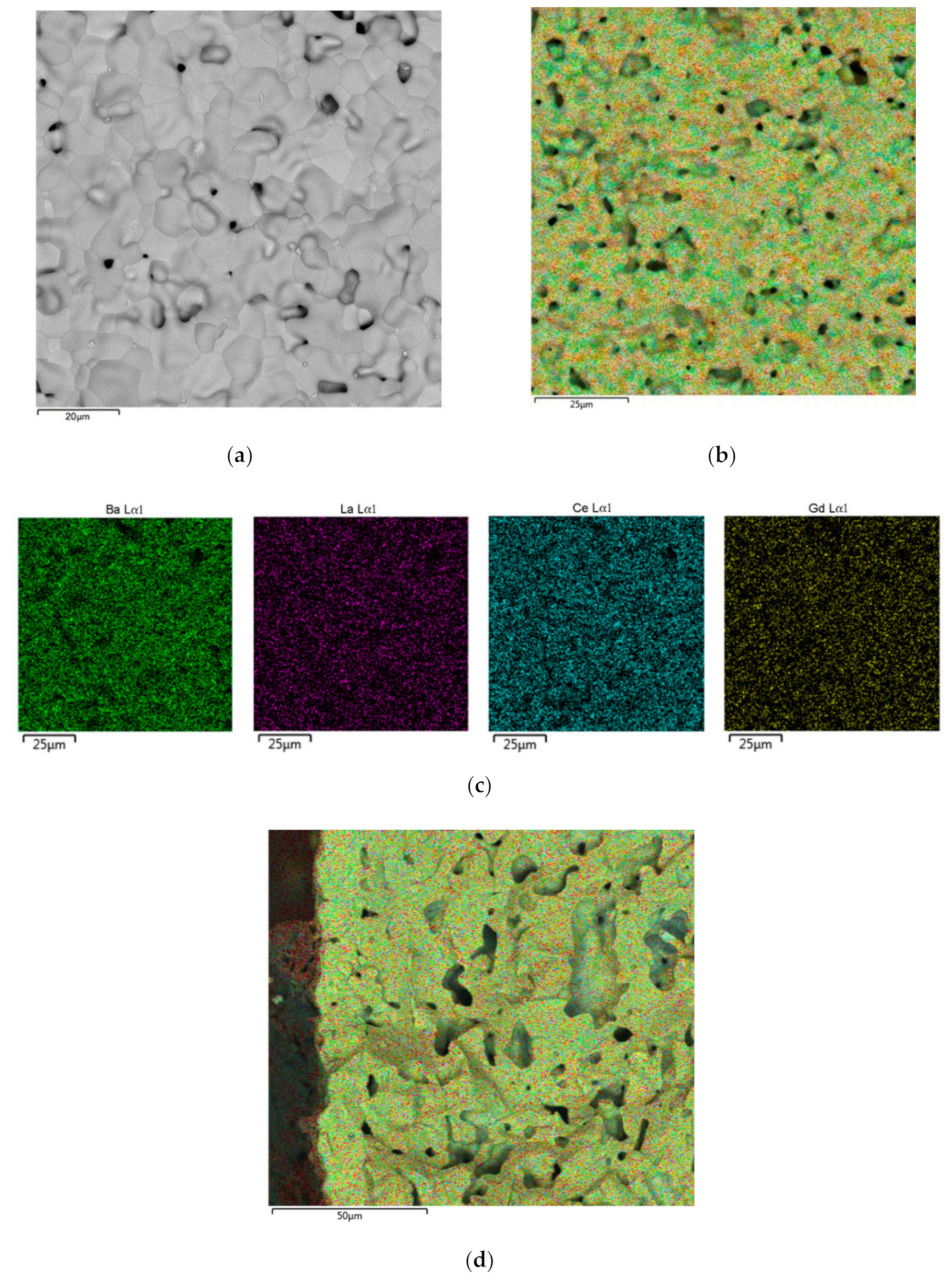
Figure 4 shows the surface of the BCGCuO film deposited from the suspension modified by the addition of J2 on the Ni-foil and annealed at 600 °C for 1 h. It can be seen from Figure 4b that the film surface is loose, porous, without cracks, and corresponds to the morphology of the initial powder (Figure 4a). The presence of iodine in the film was not registered (Figure 4c,d), which is probably due to its evaporation at the annealing temperature. The presence of Ni can be explained by the fact that, at a given temperature, the interaction of the substrate (Ni-foil) with the BCGCuO coating begins and Ni diffuses into the layer of the deposited electrolyte material.

3.3. Formation of the BCGCuO Electrolyte Films on the LNFO Substrates with the Deposited LBNOnc Sublayer

According to the results of the test deposition, EPD (U = 80 V, deposition time 1 min) for the deposition on porous LBNOnc/LNFOP and LBNOnc/LNFOss substrates was selected based on estimates of the required film thickness (up to 10 μm with a deposition weight of 6.3 mg/cm2). The current strength during deposition on the LBNOnc/LNFOP substrate was 5.84 mA, the deposition weight of the BCGCuO electrolyte layer reached 4.5 mg/cm2 (film thickness of 7 μm), while during the deposition on the LBNOnc/LNFOss substrate the current strength was 6.38 mA, and the deposition weight was significantly lower, reaching 1.3 mg/cm2 (film thickness of 2 μm). After deposition, the obtained samples BCGCuO/LBNOnc/LNFOP and BCGCuO/LBNOnc/LNFOss were sintered at a temperature of 1350 °C for 1 h.
To increase the film thickness on the BCGCuO/LBNOnc/LNFOss substrate, the deposition/sintering cycle was repeated under the same conditions. The total weight of the obtained BCGCuO layer after repeated deposition was 4.5 mg/cm2, which corresponded to a coating thickness of 7 μm. It is similar to the thickness of the electrolyte film obtained on the LBNOnc/LNFOP substrate. The final sintering of the BCGCuO/LBNOnc/LNFOP and BCGCuO/LBNOnc/LNFOss half-cells was carried out at 1450 °C, 2 h. The rate of heating and cooling was 1 °C/min.
The shrinkage of the porous substrates LNFOP and LNFOss under the electrolyte sintering conditions was 0.84% and 2.29%, respectively, while maintaining their porous structure (Figure 5). The results are in good agreement with those obtained on the preservation of the supported cathode porous structure when sintering the EPD deposited CeO2-based electrolyte films obtained from nano-sized powders [26,27].
After sintering at a temperature of 1450 °C, no Ba was detected in the composition of the electrolyte films in both half-cells which may be due to its evaporation during sintering from a thin BCGCuO electrolyte layer (total thickness of less than 10 μm). To reduce Ba loss, an attempt was made to increase electrolyte thickness. For this purpose, the EPD from the BCGCuO suspension with iodine was repeated for both half-cells. Thus, after the sintering at 1450 °C, the thickness of the electrolyte films was 12 and 10 μm, respectively. Figure 6 shows the structure of the BCGCuO/LBNOnc/LNFOss half-cell after the final sintering. The electrolyte film surface (Figure 6a) is characterized by the absence of a pronounced grain structure with the presence of bound chains and pores between them. It is seen on the cross-section image of the half-cell structure (Figure 6b) that the thickness of the BCGCuO layer is about 10 μm, which agrees well with the evaluated thickness value. According to the EDX analysis, barium is absent in the film even after the cycling deposition when the thickness of the film was increased. The sintering character of the electrolyte film (lack of grain structure) was possibly influenced by the absence of barium due to its evaporation. As can be seen from Figure 6b,c, barium is distributed in the LNFOss substrate, possibly due to its partial diffusion from the LBNO sublayer. Additionally, La diffusion from the substrate to the electrolyte film was also registered.
The thickness of the electrolyte film in the BCGCuO/LBNOnc/LNFOP half-cell was further increased by an additional three cycles of deposition/sintering (intermediate sintering between cycles was carried out at temperatures of 1200 °C, 2 h; 1350 °C, 2 h; and final sintering was performed at 1450 °C, 2 h). Additionally, to enhance the effect of barium preservation, sintering at all the stages, including intermediate ones, was carried out in a protective barium carbonate filler. The total thickness of the BCGCuO film was 21 μm. According to the EDX analysis data, the barium content in the film was close to the nominal level (~17.1 at.%).
Thus, in the case of the BCGCuO/LBNOnc/LNFOP half-cell, the electrolyte with a dense grain structure was formed with a small number of closed pores on the surface (Figure 7a), in contrast to the Ba-deficient film (Figure 6a), which was characterized by a loose structure with a large number of pores. As a result of increasing the electrolyte thickness to 21 μm, it was possible to retain barium in the BCGCuO electrolyte layer, which is confirmed by the spatial distribution of elements in the coating (Figure 7b,c). According to the EDX data, La diffusion into the electrolyte layer (~1.2 at.%) occurred but its distribution in the electrolyte layer was quite uniform (Figure 7c) compared to the results of deposition of a BCGCuO film on a dense LBNOss substrate [16], when in the electrolyte film, the sections of its heterogeneous accumulation were visible. The Gd content in the film was slightly reduced (~0.7 at.%) in both films—obtained in this study and in [16]—which may be associated with its diffusion into the substrate. No diffusion of Ni into the film was detected. Figure 7d shows a SEM image of the BCGCuO/LBNOnc/LNFOP half-cell cross section, taken after the electrochemical measurements, according to which a dense layer of sintered barium-containing electrolyte with a thickness of about 20 μm was formed.

3.4. Formation of the BCGCuO Electrolyte Film on a LNFOP Substrate

To check if the effect of the LBNOnc sublayer on the preservation of barium in the deposited BCGCuO electrolyte layer exists, the deposition of BCGCuO was performed on the LNFOP substrate without the LBNOnc sublayer. The EPD mode used was similar to that previously applied to obtain the BCGCuO/LBNOnc/LNFOP half-cell (U = 80 V, deposition time 1 min). The thickness of the electrolyte BCGCuO (10 μm) was obtained after three cycles of deposition/sintering on an LNFOP substrate (intermediate sintering between cycles were carried out at temperatures of 1200 °C, 2 h; 1350 °C, 2 h; and final sintering at 1450 °C, 2 h). Sintering at all the stages, including intermediate stages, was carried out in a protective filler, as it was suggested in [21].
After the final sintering, barium was not detected in the electrolyte layer, thereby repeating the results obtained by sintering the BCGCuO electrolyte of the same thickness on the LBNOnc sublayer, i.e., in the structure of BCGCuO/LBNOnc/LNFOP. It can be concluded that the prevailing reason for the loss of barium may be associated with its diffusion into the substrate. However, due to low film thickness, evaporation can also have an influence on Ba loss, even during the sintering performed in the protective filler. In order to increase the thickness of the BCGCuO coating, four additional deposition/sintering cycles were carried out (intermediate sintering between the cycles was carried out at temperatures of 1200 °C, 2 h; 1200 °C, 2 h; 1350 °C, 2 h; final sintering—1450 °C, 2 h) with a total thickness of about 28 microns. Sintering at all stages was performed with a bulk of barium carbonate. According to the EDX data, Ba content in the electrolyte layer was ~19.3 at.%, while La and Gd content were 1.3 and 1 at.%, respectively, due to interdiffusion which occurred between the LNFOP substrate and the BCGCuO electrolyte layer. The content of Ba and Gd turned out to be higher in comparison with the BCGCuO/LBNOnc/LNFOP sample, which is probably due to the greater thickness of the coating.

3.5. Formation of the BCGCuO Electrolyte Films on LBNOss Substrates

The EPD of the BCGCuO electrolyte film on the LBNOss substrate (designated as LBNOss_1) was performed at a deposition voltage of 80 V for 1 min with the initial current being approximately 6 mA. Three cycles of deposition/sintering were carried out (intermediate sintering at temperatures of 1200 °C, 2 h and 1350 °C, 2 h, and final sintering—at 1450 °C, 2 h). Sintering at all the stages, including intermediate stages, was carried out in protective barium carbonate filler. The total coating thickness was 10 μm. The film surface had well-developed grain structures with defects in the shape of closed pores and convex chambers, perhaps repeating the substrate surface structure (Figure 8a). The spatial distribution of the elements in the coating (Figure 8b,c) confirmed the presence of barium, the content of which is closer to the nominal level (~20.7 at.%) compared to that in the BCGCuO film obtained on the LBNOnc/LNFOP substrate (~17.1 at.%). However, the content of Gd (~0.8 at.%) still did not reach the nominal value and there was diffusion of La (~1.4 at.%) into the coating. Additional deposition/sintering cycles were performed to increase the film thickness. However, at the thickness of about 17 μm, the BCGCuO coating partly peeled off from the substrate during sintering. This was probably due to internal stresses in the electrolyte layer caused by the difference in the BCGCuO and LBNO TEC values, as, according to [25], the TEC value of the BCGCuO electrolyte changes from 10.5 × 10⁻⁶ K−1 in the temperature range 100–575 °C to 8.6 × 10⁻⁶ K−1 in the temperature range 575–900 °C, and the TEC of LBNO is 15.2 × 10⁻⁶ K−1 in the 100–900 °C range. The TEC mismatch influence, evening out in the case of thin films, becomes pronounced when increasing the BCGCuO film thickness deposited on the LBNOss bulk substrate (~1 mm in this study).
For further experiments, EPD of the BCGCuO electrolyte film on the LBNOss substrate (designation LBNOss_2) was repeated under the same conditions up to the electrolyte thickness of approximately 10 μm, as it is seen on the cross-sectional image of the cell taken after the electrochemical study (Figure 8d). As in the case of the BCGCuO/LBNOss_1 half-cell, Ba content in the electrolyte coating of the BCGCuO/LBNOss_2 half-cell was close to nominal level. The cell parameters calculated for the BCGCuO film deposited on the LBNOss substrate, equal to a = 8.7921(26) Å, b = 6.2196(25) Å, and c = 6.2225(21) Å, are close to those for the as-prepared BCGCuO powder (Table 1), which reveals the EDX data, showing that in this film, Ba content was preserved during the sintering. However, there is still Gd-La interdiffusion between the substrate and the electrolyte layers which may influence the functional properties of the film. No diffusion of Ni into the film was detected.
The results for all prepared half-cells are summarized in Table 2. It is seen that the presence of the bulk LBNOss substrate and simultaneously using the BaCO3 as a protective filler can be an effective means of preserving Ba content in the BCGCuO electrolyte close to the nominal level during sintering at high temperatures. The thin LBNOnc film (approximately 10 μm) is less effective in this regard and, when using LNFOP substrate with or without this film, the only method of preventing Ba loss in the electrolyte layer is to increase its thickness above 20 μm. Due to a mismatch in the TEC values of LBNO and BCGCuO, which is less of a factor when using thin films, additional study is necessary to establish the optimal thickness of a LBNO layer, which would allow the deposition on LNFO substrates of a film with nominal Ba content and the required thickness.

3.6. Electrical Properties of the Electrolyte BCGCuO Film Formed on Various Cathode Substrates

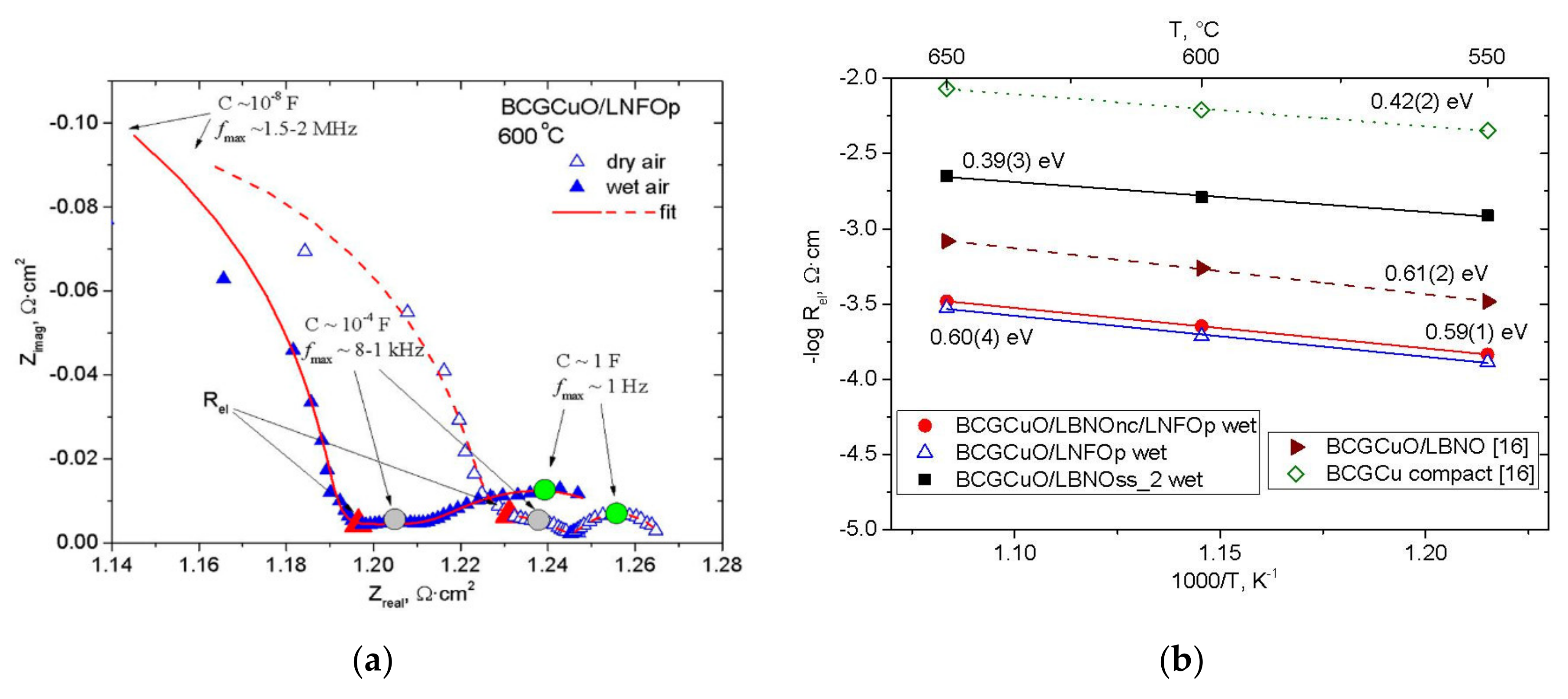
For the electrochemical studies of the half-cells of BCGCuO/LBNOnc/LNFOP, BCGCuO/LNFOP and BCGCuO/LBNOss (Table 2) were used. For that, Pt collectors were symmetrically deposited on both sides of the half-cells. Figure 9a shows examples of the impedance spectra of the Pt|BCGCuO/LNFOP|Pt cell obtained at a temperature of 600 °C in wet and dry air atmospheres. In the first experiment, the air (flow rate of 2 L/h) was bubbled through the bubbler heated up to 25 °C; in the second experiment, the air went through the container with zeolites. The processing of the spectra was carried out by a circuit of series-connected resistance Rel and three parallel-connected RQ chains. The high-frequency response in the spectrum with a characteristic frequency of 1.5–2 MHz in the wet and dry air, respectively, and with a characteristic capacitance value of ~10–8 F, as widely accepted, refers to the grain boundaries of the electrolyte [33,34].
The electrode response with a characteristic capacitance of ~10−4 F and a characteristic frequency of ~1–8 kHz probably refers to oxygen diffusion in the electrode. With transition from the dry to the wet air atmosphere, the relaxation frequency decreases, which indicates process slowdown. The low frequency process with a capacity of ~100 F and a frequency in the maximum of ~1 Hz is typically related to gas diffusion limitations in the porous electrode structure and on the electrode surface. It also becomes more pronounced in the wet air. The presence of water vapor partially blocks the active electrode sites towards the oxygen reduction reaction [35], which leads to an increase in the total electrode polarization resistance. At the same time, the process of charge transfer through the electrode–electrolyte interface, enhanced owing to an increased electronic conductivity in the protonic electrolyte, is overlapped by the slower electrode processes and not observed on the spectra. The electrolyte resistance, Rel, was taken as an interception of the right end of the depressed semicircle, fitting the grain boundary response with the Zreal axis (Figure 9a). It is seen that in the dry air, electrolyte resistance increases due to decreasing the partial protonic conductivity [6,34].
Figure 9b shows Arrhenius dependences of the reciprocal Rel (electrical conductivity) of the BCGCuO films on various cathode substrates obtained in this study. For the sake of comparison, the conductivity of the BCGCuO film deposited on the dense model LBNOss cathode and the conductivity of the BCGCuO ceramic sample, measured by the four-probe method in wet air [16], are also presented. The film deposited on the LBNOss substrate showed the highest conductivity, close to that of the compact sample. The reduction in the total conductivity value for the films deposited on the LBNOnc/LNFOP and LNFOP substrates is probably the result of Ba-deficiency. This generally has a significant effect on the electrical properties [20]. When La diffuses into the film and there is partial substitution in both the Ba and Ce positions, then the conductivity can also be reduced in comparison to the Gd-doped BaCeO3 [8]. The latter factor seems to be more pronounced for the film deposited on the LNFOP substrate, which has the lowest conductivity value.
The film obtained on the LBNOss substrate, according to the impedance spectroscopy data, possessed the highest electrical conductivity among the films deposited on the various cathode substrates, amounting 1.6 mS/cm at 600 °C. This value is lower than that for the compact BCGCuO sample (6.2 mS/cm) [16]; however, it is higher than that derived from the impedance spectroscopy data for the BCGCuO electrolyte deposited on the anode substrate (1.1 mS/cm) [7]. Electrolyte conductivity in the cell with the supporting cathode substrate can be increased via activation of the thick cathode’s performance, used for the functional sublayer Ba-containing cathode materials with a higher level of MIEC conductivity [36] and/or by the introduction of electrochemically active additives in the porous cathode substrate structure [37], as well as by applying the electrochemically active anodes [38]. According to the XRD data (Figure S6), the orthorhombic structure (sp. gr. Pmcn) of the BCGCuO compact sample was preserved after the sintering at 1450 °C. The values of the cell’s parameters were a = 8.7901(26) Å, b = 6.2227(25) Å, and c = 6.2238(21) Å, which are close to those obtained for the base powder before sintering (Table 1). Nevertheless, the conductivity of the BCGCuO compact sample was lower than those of current state-of-the-art proton-conducting electrolytes such as BaZr0.1Ce0.7Yo.1Ybo.1O3-δ (~13–15 mS/cm at 550 °C in wet air [39,40]) or BaCe0.6Zr0.2Dy0.2O3-δ (~35 mS/cm at 600 °C in wet air [41]). Thus, future studies should be oriented on the development of the EPD technology for these or similar materials, taking into account the features observed in the present study.

4. Conclusions

This paper presents the results of the study of the formation by electrophoretic deposition of the thin-film BCGCuO proton-conducting solid electrolyte on the porous LBNOss, LNFOss, and LNFOp cathode substrates, including the LNFOp and LNFOss substrates with the LBNOnc sublayer. It focuses on the preventive measures to preserve barium content in the electrolyte at the nominal level during deposition and high-temperature sintering. Special attention is also given to the preservation of the porous structure of the cathode substrates during all deposition/sintering cycles. The EPD modes for deposition of LBNOnc and BCGCuO films were established in the test depositions on the Ni-foil. The influence of molecular iodine on the deposition kinetics was studied. It was shown that the addition of iodine allowed a significant increase in the deposition weight of the BCGCuO coatings. As a result of a series of experiments on the formation of the BCGCuO electrolyte layer on porous LNFO cathodes (with and without the thin LBNO sublayer (~10 μm)), it was determined that electrolyte thickness plays a major role in ensuring its nominal composition. Thus, the preservation of barium in the electrolyte layer after sintering at a temperature of 1450 °C (2 h) was achieved only at a thickness of ~20 μm and more. When using the bulk LBNOss cathode (~1 mm), barium was retained during sintering, even at the electrolyte film thickness of 10 μm, which revealed the role of the LBNOss substrate as a barium source. The film obtained on the LBNOss substrate, according to the impedance spectroscopy study, possessed the highest electrical conductivity among the films deposited on the various cathode substrates. Nevertheless, an increase in BCGCuO film thickness on the bulk LBNOss substrate (over about 17 μm) led to delamination and cracking of the electrolyte due to internal stresses in the layer caused by the thermal expansion mismatch of the materials. Thus, the use of bulk LBNO substrates is not the optimal solution to the problem and, for the assured formation of the electrolyte films in the required thickness range, additional studies are necessary to determine the optimal thickness of the LBNO sublayer to prevent Ba loss, using it as a Ba source and, at the same time, preserving the quality of the electrolyte films.

Supplementary Materials

The following are available online at https://www.mdpi.com/2076-3417/10/18/6535/s1.

Author Contributions

Conceptualization, methodology, investigation, formal analysis, writing—original draft preparation, E.K.; formal analysis, visualization, A.K.; investigation, K.S.; investigation, formal analysis, visualization, A.F.; conceptualization, supervision, writing—review and editing, E.P. All authors have read and agreed to the published version of the manuscript.

Funding

This research received no external funding

Acknowledgments

This work was performed in the framework of the IEP UB RAS state assignment (EPD technology development) and the IHTE UB RAS budget task (SOFC technology development). The XRD and microstructure study was carried out using the equipment of the Shared Access Center “Composition of compounds” (Institute of High Temperature Electrochemistry, Ural Branch of the Russian Academy of Sciences, Yekaterinburg, Russia). The authors acknowledge Zhuravlev, V.D., the head of the Laboratory of chemistry of compounds of rare-earth elements (Institute of Solid State Chemistry, UB RAS, Yekaterinburg, Russia), Bogdanovich, N.M., scientific researcher of the Laboratory of solid oxide fuel cells (IHTE UB RAS), and Lyagaeva, J.G., senior scientific researcher of the Laboratory of Electrochemical Devices Based on Solid Oxide Proton Electrolytes (IHTE UB RAS) for the development of the synthesis methods used in this study.

Conflicts of Interest

The authors declare no conflict of interest.

References

  1. Hossain, S.; Abdalla, A.M.; Jamain, S.N.B.; Zaini, J.H.; Azad, A.K. A review on proton conducting electrolytes for clean energy and intermediate temperature-solid oxide fuel cells. Renew. Sustain. Energy Rev. 2017, 79, 750–764. [Google Scholar] [CrossRef]
  2. Irshad, M.; Siraj, K.; Raza, R.; Ali, A.; Tiwari, P.; Zhu, B.; Rafique, A.; Ali, A.; Ullah, M.K.; Usman, A. A Brief Description of High Temperature Solid Oxide Fuel Cell’s Operation, Materials, Design, Fabrication Technologies and Performance. Appl. Sci. 2016, 6, 75. [Google Scholar] [CrossRef] [Green Version]
  3. Wang, Q.; Wei, H.-H.; Xu, Q. A Solid Oxide Fuel Cell (SOFC)-Based Biogas-from-Waste Generation System for Residential Buildings in China: A Feasibility Study. Sustainability 2018, 10, 2395. [Google Scholar] [CrossRef] [Green Version]
  4. Tarancón, A. Strategies for Lowering Solid Oxide Fuel Cells Operating. Energies 2009, 2, 1130–1150. [Google Scholar] [CrossRef]
  5. Matsumoto, H.; Kawasaki, Y.; Ito, N.; Enoki, M.; Ishihara, T. Relation between electrical conductivity and chemical stability of BaCeO3–based proton conductors with different trivalent dopants. Electrochem. Solid State Lett. 2007, 10, B77–B80. [Google Scholar] [CrossRef]
  6. Danilov, N.; Pikalova, E.; Lyagaeva, J.; Antonov, B.; Medvedev, D.; Demin, A.; Tsiakaras, P. Grain and grain boundary transport in BaCe0.5Zr0.3Ln0.2O3−δ (Ln–Y or lanthanide) electrolytes attractive for protonic ceramic fuel cells application. J. Power Sources 2017, 366, 161–168. [Google Scholar] [CrossRef]
  7. Pikalova, E.; Medvedev, D. Effect of anode gas mixture humidification on the electrochemical performance of the BaCeO3-based protonic ceramic fuel cell. Int. J. Hydrogen Energy 2016, 41, 4016–4025. [Google Scholar] [CrossRef]
  8. Amsif, M.; Marrero-Lopez, D.; Ruiz-Morales, J.C.; Savvin, S.N.; Gabás, M.; Nunez, P. Influence of rare-earth doping on the microstructure and conductivity of BaCe0.9Ln0.1O3−δ proton conductors. J. Power Sources 2011, 196, 3461–3469. [Google Scholar] [CrossRef]
  9. Medvedev, D.A.; Gorbova, E.V.; Demin, A.K.; Tsiakaras, P. Conductivity of Gd-doped BaCeO3 protonic conductor in H2–H2O–O2 atmospheres. Int. J. Hydrogen Energy 2014, 39, 21547–21552. [Google Scholar] [CrossRef]
  10. Lyagaeva, J.G.; Vdovin, G.K.; Medvedev, D.A. Distinguishing Bulk and Grain Boundary Transport of a Proton-Conducting Electrolyte by Combining Equivalent Circuit Scheme and Distribution of Relaxation Times Analyses. J. Phys. Chem. C 2019, 123, 21993–21997. [Google Scholar] [CrossRef]
  11. Dunyushkina, L.A. Solid Oxide Fuel Cells with film electrolyte: Problems and perspectives. Electrochem. Energetics 2016, 16, 196–206. [Google Scholar] [CrossRef]
  12. Pikalova, E.Y.; Kalinina, E.G. Place of Electrophoretic Deposition Among Thin-Film Methods Adapted to the Solid Oxide Fuel Cell Technology: A Short Review. Int. J. Energy Prod. Manag. 2019, 4, 1–27. [Google Scholar] [CrossRef] [Green Version]
  13. Agarwal, V.; Liu, M. Colloidal Processing of BaCeO3-Based Electrolyte Films. J. Electrochem. Soc. 1996, 143, 3239–3244. [Google Scholar] [CrossRef]
  14. Dubal, S.U.; Bhosale, C.H.; Jadhav, L.D. Performance of spray deposited Gd-doped barium cerate thin films for proton conducting SOFCs. Ceram. Int. 2015, 41, 5607–5613. [Google Scholar] [CrossRef]
  15. Kalinina, E.G.; Pikalova, E.Y.; Farlenkov, A.S. Electrophoretic Deposition of Thin-Film Coatings of Solid Electrolyte Based on Microsize BaCeO3 Powders. Russ. J. Appl. Chem. 2018, 91, 934–941. [Google Scholar] [CrossRef]
  16. Kalinina, E.G.; Pikalova, E.Y.; Kolchugin, A.A.; Pikalova, N.S.; Farlenkov, A.S. Comparative Study of Electrophoretic Deposition of Doped BaCeO3-Based Films on La2NiO4+δ and La1.7Ba0.3NiO4+δ Cathode Substrates. Materials 2019, 12, 2545. [Google Scholar] [CrossRef] [Green Version]
  17. Kalinina, E.G.; Pikalova, E.Y. New trends in the development of electrophoretic deposition method in the solid oxide fuel cell technology: Theoretical approaches, experimental solutions and development prospects. Russ. Chem. Rev. 2019, 88, 1179. [Google Scholar] [CrossRef]
  18. Besra, L.; Liu, M. A review on fundamentals and applications of electrophoretic deposition (EPD). Progr. Mater. Sci. 2007, 52, 1–61. [Google Scholar] [CrossRef]
  19. Pikalova, E.Y.; Kalinina, E.G. Electrophoretic deposition in the solid oxide fuel cell technology: Fundamentals and recent advances. Renew. Sustain. Energy Rev. 2019, 116, 109440. [Google Scholar] [CrossRef]
  20. Medvedev, D.; Brouzgou, A.; Demin, A.; Tsiakaras, P. Proton-Conducting Electrolytes for Solid Oxide Fuel Cell Applications. In Advances in Medium and High Temperature Solid Oxide Fuel Cell Technology; Boaro, M., Salvatore, A.A., Eds.; Springer Nature: Cham, Switzerland, 2016; Volume 574, pp. 77–119. [Google Scholar] [CrossRef]
  21. Mercadelli, E.; Montaleone, D.; Gondolini, A.; Pinasco, P.; Sanson, A. Tape-cast asymmetric membranes for hydrogen separation. Ceram. Int. 2017, 43, 8010–8017. [Google Scholar] [CrossRef]
  22. Park, I.; Kim, J.; Lee, H.; Park, J.; Shin, D. BaCeO3–BaCe0.8Sm0.2O3−δ bi-layer electrolyte-based protonic ceramic fuel cell. Solid State Ion. 2013, 252, 152–156. [Google Scholar] [CrossRef]
  23. Lyagaeva, J.; Danilov, N.; Pikalova, E.Y.; Plaksin, S.; Brouzgou, A.; Demin, A.; Tsiakaras, P. A detailed analysis of thermal and chemical compatibility of cathode materials suitable for BaCe0.8Y0.2O3-δ and BaZr0.8Y0.2O3−δ proton electrolytes for solid oxide fuel cell application. Int. J. Hydrogen Energy 2017, 42, 1715–1723. [Google Scholar] [CrossRef]
  24. Pikalova, E.Y.; Bogdanovich, N.M.; Kolchugin, A.A.; Osinkin, D.A.; Bronin, D.I. Electrical and Electrochemical Properties of La2NiO4+δ-Based Cathodes in Contact with Ce0.8Sm0.2O2 − δ Electrolyte. Procedia Eng. 2014, 98, 105–110. [Google Scholar] [CrossRef] [Green Version]
  25. Pikalova, E.Y.; Kolchugin, A.A. The Influence of the Substituting Element (M = Ca, Sr, Ba) in La1.7M0.3NiO4+δ on the Electrochemical Performance of the Composite Electrodes. Eurasian Chem. Technol. J. 2016, 18, 3–11. [Google Scholar] [CrossRef] [Green Version]
  26. Kalinina, E.G.; Pikalova, E.Y.; Kolchugin, A.A.; Pikalov, S.M.; Kaigorodov, A.S. Cyclic electrophoretic deposition of electrolyte thin-films on the porous cathode substrate utilizing stable suspensions of nanopowder. Solid State Ion. 2017, 302, 126–132. [Google Scholar] [CrossRef]
  27. Kalinina, E.G.; Bogdanovich, N.M.; Bronin, D.I.; Pikalova, E.Y.; Pankratov, A.A. Formation of Thin-Film Electrolyte by Electrophoretic Deposition onto Modified Multilayer Cathode. Russ. J. Appl. Chem. 2019, 92, 191–198. [Google Scholar] [CrossRef]
  28. Dusoulier, L.; Cloots, R.; Vertruyen, B.; Moreno, R.; Burgos-Montes, O.; Ferrari, B. YBa2Cu3O7−x dispersion in iodine acetone for electrophoretic deposition: Surface charging mechanism in a halogenated organic media. J. Eur. Ceram. Soc. 2011, 31, 1075–1086. [Google Scholar] [CrossRef] [Green Version]
  29. Chen, F.; Liu, M. Preparation of yttria-stabilized zirconia (YSZ) films on La0.85Sr0.15MnO3 (LSM) and LSM–YSZ substrates using an electrophoretic deposition (EPD) process. J. Eur. Ceram. Soc. 2001, 21, 127–134. [Google Scholar] [CrossRef]
  30. Bartolomeo, E.D.; Zunic, M.; Chevallier, L.; D’Epifanio, A.; Licoccia, S.; Traversa, E. Fabrication of proton conducting solid oxide fuel cells by using electrophoretic deposition. ECS Trans. 2009, 25, 577–684. [Google Scholar] [CrossRef]
  31. Besra, L.; Uchikoshi, T.; Suzuki, T.; Sakka, Y. Experimental verification of pH localization mechanism of particle consolidation at the electrode/solution interface and its application to pulsed DC electrophoretic deposition (EPD). J. Eur. Ceram. Soc. 2010, 30, 1187–1193. [Google Scholar] [CrossRef]
  32. Mishra, M.; Sakka, Y.; Uchikoshi, T.; Besra, L. pH localization: A case study during electrophoretic deposition of ternary max phase carbide-Ti3SiC2. J. Ceram. Soc. Jpn. 2013, 121, 348–354. [Google Scholar] [CrossRef] [Green Version]
  33. Lacz, A. Effect of microstructure on chemical stability and electrical properties of BaCe0.9Y0.1O3 − δ. Ionics 2016, 22, 1405–1414. [Google Scholar] [CrossRef] [Green Version]
  34. Lyagaeva, J.; Antonov, B.; Dunyushkina, L.; Kuimov, V.; Medvedev, D.; Demin, A.; Tsiakaras, P. Acceptor doping effects on microstructure, thermal and electrical properties of proton-conducting BaCe0.5 Zr0.3Ln0.2O3−δ (Ln = Yb, Gd, Sm, Nd, La or Y) ceramics for solid oxide fuel cell applications. Electrochim. Acta 2016, 192, 80–88. [Google Scholar] [CrossRef]
  35. Strandbakke, R.; Cherepanov, V.A.; Zuev, A.Y.; Tsvetkov, D.S.; Argirusis, C.; Sourkouni, G.; Prünte, S.; Norby, T. Gd- and Pr-based double perovskite cobaltites as oxygen electrodes for proton ceramic fuel cells and electrolyser cells. Solid State Ion. 2015, 278, 120–132. [Google Scholar] [CrossRef]
  36. Tarutin, A.P.; Gorshkov, M.Y.; Bainov, I.N.; Vdovin, G.K.; Vylkov, A.I.; Lyagaeva, J.G.; Medvedev, D.A. Barium-doped nickelates Nd2-xBaxNiO4+δ as promising electrode materials for protonic ceramic electrochemical cells. Ceram. Int. 2020, in press. [Google Scholar] [CrossRef]
  37. Beresnev, S.M.; Bobrenok, O.F.; Kuzin, B.L.; Bogdanovich, N.M.; Kurteeva, A.A.; Osinkin, D.A.; Vdovin, G.K.; Bronin, D.I. Single Fuel Cell with Supported LSM Cathode. Russ. J. Electrochem. 2012, 48, 969–975. [Google Scholar] [CrossRef]
  38. Osinkin, D.A. Complementary effect of ceria on the hydrogen oxidation kinetics on Ni-Ce0.8Sm0.2O2-δ anode. Electrochim. Acta 2020, 330, 135257. [Google Scholar] [CrossRef]
  39. Yang, L.; Wang, S.; Blinn, K.; Liu, M.; Liu, Z.; Cheng, Z.; Liu, M. Enhanced Sulfur and Coking Tolerance of a Mixed Ion Conductor for SOFCs: BaZr0.1Ce0.7Y0.2–xYbxO3−δ. Science 2009, 326, 126–129. [Google Scholar] [CrossRef] [Green Version]
  40. Wang, S.; Zhao, F.; Zhang, L.; Chen, F. Synthesis of BaCe0.7Zr0.1Y0.1Yb0.1O3-δ proton conducting ceramic by a modified Pechini method. Solid State Ion. 2012, 213, 29–35. [Google Scholar] [CrossRef]
  41. Danilov, N.A.; Lyagaeva, J.G.; Medvedev, D.A.; Demin, A.K.; Tsiakaras, P. Transport properties of highly dense proton-conducting BaCe0.8–xZrxDy0.2O3−δ materials in low- and high-temperature ranges. Electrochim. Acta 2018, 284, 551–559. [Google Scholar] [CrossRef]
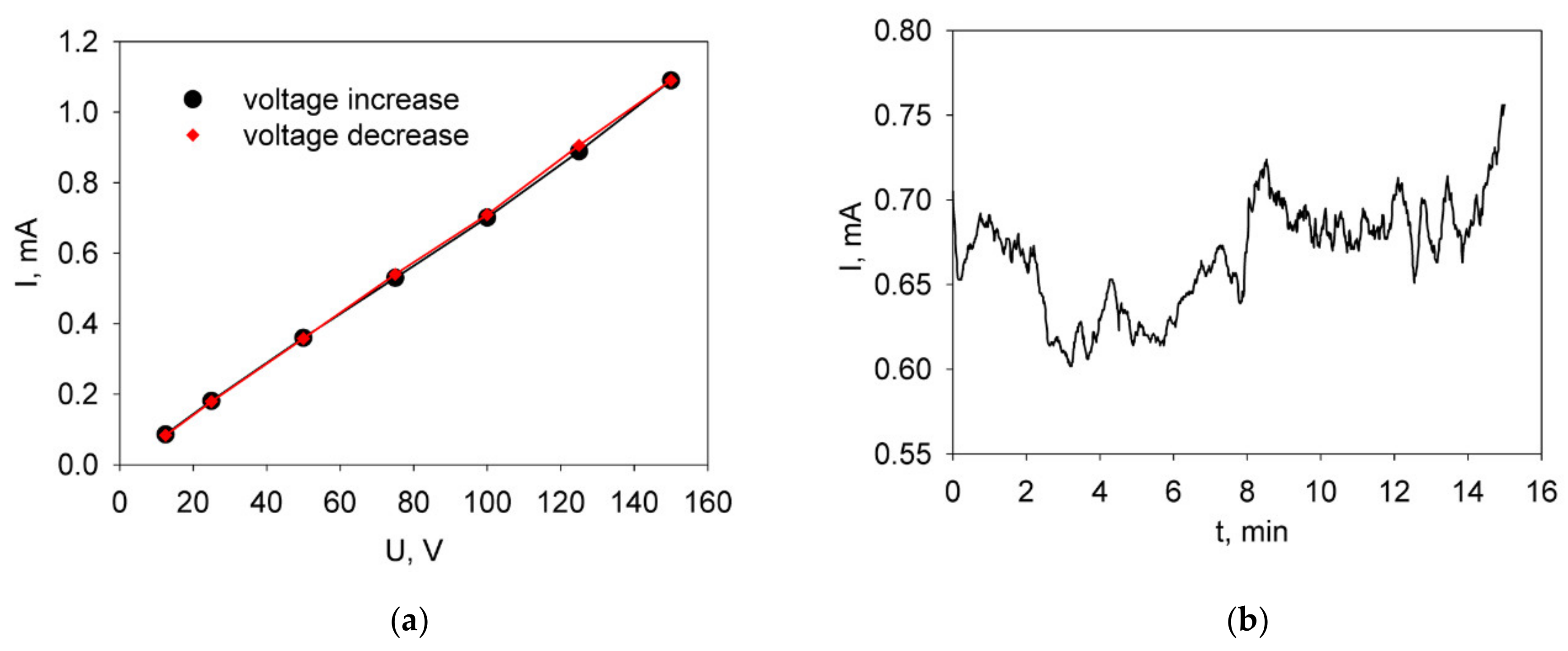
Figure 1. The current–voltage characteristic in the voltage range from 12 to 150 V (a) and the dependence of the current strength on time at a constant voltage of 100 V (b) obtained during the test EPD on the Ni-foil from a suspension of the LBNOnc powder (10 g/L) in isopropanol with J2 additive (0.4 g/L).
Applsci 10 06535 g001
Figure 2. Time dependencies of the deposition weight of the BCGCuO film in test deposition on the Ni-foil performed at a constant voltage of 80 V from a suspension of BCGCuO in a mixed dispersion isopropanol/acetylacetone medium (70/30 vol.%) (1) and from the suspension modified by the addition of molecular iodine (2).
Applsci 10 06535 g002
Figure 3. Deposition kinetics of the BCGCuO film on the Ni-foil: Dependences of the current strength on time at a constant voltage of 80 V for the deposition from a suspension (10 g/L) in the mixed dispersion isopropanol/acetylacetone medium (70/30 vol.%) without J2 (a) and with J2 additive (0.4 g/L) (b); The current–voltage characteristic in the voltage range from 12 to 150 V obtained for the deposition from the BCGCuO suspension with J2 additive (c).
Applsci 10 06535 g003
Figure 4. SEM images of the initial BCGCuO powder (a) and the BCGCuO film deposited on the Ni-foil and annealed at 600 °C, 1 h (b); EDX mapping images—integrated (c) and for the individual elements (d).
Applsci 10 06535 g004
Figure 5. SEM images of back sides of the porous electrode substrates after the BCGCuO electrolyte sintering at 1450 °C, 2 h: (a) LNFOP in BCGCuO/LBNOnc/LNFOP and (b) LNFOss in BCGCuO/LBNOnc/LNFOss.
Applsci 10 06535 g005
Figure 6. SEM images of the BCGCuO/LBNOnc/LNFOss half-cell after cycling EPD (3 cycles): the BCGCuO electrolyte surface (a); EDX mapping images (cross-sectional)—integrated (b) and for the individual elements (c).
Applsci 10 06535 g006
Figure 7. SEM images of the BCGCuO/LBNOnc/LNFOP half-cell with the BCGCuO electrolyte after 5 cycles of deposition/sintering: the electrolyte surface (a); EDX mapping electrolyte surface images—integrated (b) and obtained for the individual elements (c); the integrated EDX mapping image of the BCGCuO/LBNOnc/LNFOP half-cell cross-section taken after the electrochemical study (d).
Applsci 10 06535 g007
Figure 8. SEM images of the BCGCuO electrolyte in the BCGCuO/LBNOss_1 half-cell (after 3 cycles of deposition/sintering): surface (a); EDX images-integrated (b) and for individual elements (c); the an EDX image of the cross-section of BCGCuO/LBNOss_2 taken after the electrochemical study(d).
Applsci 10 06535 g008
Figure 9. Electrical properties of BCGCuO electrolyte deposited at various cathode substrates: Examples of the spectra collected in wet and dry air atmospheres for the Pt|BCGCuO/LNFOP|Pt cell (a); Arrhenius plots of the electrical conductivity for the thin BCGCuO electrolyte films calculated from the electrochemical impedance spectroscopy data obtained using various half cells (shown in the legend) in comparison with the BCGCuO compact conductivity (b).
Applsci 10 06535 g009
Table 1. Characterization of the powdered electrolyte and electrode materials.
MaterialSynthesis MethodDesignationXRD DataSBET, m2/g
(After Final Ball-Milling)
Electrolyte BaCe0.89Gd0.1Cu0.01O3-δnitrate combustion methodBCGCuOorthorhombic structure
(sp. gr. Pmcn)
a = 8.7929(21) Å
b = 6.2333(13) Å
c = 6.2197(9) Å
3.01(7)
Electrode La1.7Ba0.3NiO4+δtwo-stage solid state reaction methodLBNOsstetragonal structure
(sp. gr. I4/mmm)
a = 3.8466(5) Å,
c = 12.7985(21) Å
1.60(2)
nitrate combustion methodLBNOnctetragonal structure
(sp. gr. I4/mmm)
a = 3.8582(4) Å,
c = 12.8378(37) Å
2.21(6)
Electrode LaNi0.6Fe0.4O3-δmodified Pechini methodLNFOprhombohedral structure (sp. gr. R-3c)
a = 5.5053(13) Å
b = 5.5053(13) Å,
c = 13.2727(31) Å
6.50(13)
(as-prepared)
1.06(2) (calcinated at 1180 °C)
two-stage solid state reaction methodLNFOssrhombohedral structure
(sp. gr. R-3c)
a = 5.5062(12) Å
b = 5.5062(12) Å
c = 13.2501(31) Å
1.50(3)
Table 2. Features of formation of BCGCuO electrolyte on various cathode substrates: number of the EPD cycles, sintering conditions, and electrolyte film thickness and content (EDX analysis data).
Half-CellStageTotal Number of Cycles//Number of Cycles on the Stage, Sintering ConditionsBCGCuO Film, µmElectrolyte Film Content (at.%)
BCGCuO/
LBNOnc/LNFOP
12//2
LBNO (1350 °C, 1 h)
BCGCuO (1450 °C, 2 h)
7Ba is not detected
23//1
BCGCuO (1450 °C, 2 h)
12Ba is not detected
36//3
BCGCuO (1200 °C, 2 h)
BCGCuO (1350 °C, 2 h)
BCGCuO (1450 °C, 2 h)
sintering with BaCO3
21O–66
Ni–0
Ba–17.1
La–1.2
Ce–15
Gd–0.7
BCGCuO/
LBNOnc/LNFOss
13//3
LBNO (1350 °C, 1 h)
BCGCuO (1350 °C, 1 h)
BCGCuO (1450 °C, 2 h)
7Ba is not detected
24//1
BCGCuO (1450 °C, 2 h)
10O–64
Ni, Cu, Ba–0
La–12
Ce–22
Gd–2
BCGCuO/
LNFOP
13//3
BCGCuO (1200 °C, 2 h)
BCGCuO (1350 °C, 2 h)
BCGCuO (1450 °C, 2 h)
sintering with BaCO3
10O–63.5
Ba–0
La–14
Ce–21
Gd–1.5
27//4
BCGCuO (1200 °C, 2 h)
BCGCuO (1350 °C, 2 h)
BCGCuO (1450 °C, 2 h)
sintering with BaCO3
28O–61
Ba–19.3
La–1.3
Ce–17.4
Gd–1
BCGCuO/
LBNOss_1
13//3
BCGCuO (1200 °C, 2 h)
BCGCuO (1350 °C, 2 h)
BCGCuO (1450 °C, 2 h)
sintering with BaCO3
10O–60.1
Ba–20.7
La–1.4
Ce–17
Gd–0.8
26//3
BCGCuO (1200 °C, 2 h)
BCGCuO (1350 °C, 2 h)
BCGCuO (1450 °C, 2 h)
sintering with BaCO3
17O–60.4
Ba–20
La–1.5
Ce–17
Gd–1.1
BCGCuO/
LBNOss_2
13//3
BCGCuO (1200 °C, 2 h)
BCGCuO (1350 °C, 2 h)
BCGCuO (1450 °C, 2 h)
sintering with BaCO3
10O–60
Ba–19.8
La–1.4
Ce–18
Gd–0.8