Article

Clarification of Features of the Wheel Movement with a Perspective Constructive Scheme on a Rail

1
Department of Logistics and Traffic Safety, Educational and Scientific Institute of Transport and Building, Volodymyr Dahl East Ukrainian National University, Central Avenue 59A/303, 93400 Severodonetsk, Ukraine
2
Department of Transport and Handling Machines, Faculty of Mechanical Engineering, University of Žilina, Univerzitná 8215/1, 010 26 Žilina, Slovakia
3
Department of Railway and Road Technology, Lift and Care Systems, Educational and Scientific Institute of Transport and Building, Volodymyr Dahl East Ukrainian National University, Central Avenue 59A/303, 93400 Severodonetsk, Ukraine
*
Author to whom correspondence should be addressed.
Appl. Sci. 2020, 10(19), 6758; https://doi.org/10.3390/app10196758
Submission received: 13 August 2020 / Revised: 19 September 2020 / Accepted: 24 September 2020 / Published: 27 September 2020
(This article belongs to the Section Mechanical Engineering)

Abstract

:
The article presents the continuation of studies of the features of the wheel movement the traditional and perspective constructive scheme on a rail. Unlike the traditional design, the perspective constructive scheme of the wheel allows independent relative rotation of the support surface wheel and of its guide surface (flange) relative to their common axis of rotation. Previous authors’ works did not take into account the influence of the level of slippage in the main contact of the wheel with the rail on the value of the slippage rate in its flange contact. This article further examines the influence of this factor for both wheel designs. The results of the presented studies confirm the possibility of reducing slippage in the flange contact with the rail for a wheel of a promising design scheme in comparison with a traditional wheel. Reducing the power of friction forces in the contact of the wheel flange of a promising design scheme will reduce the resistance to movement of such a wheel along the rail, especially in curved track sections.

1. Introduction

A wheel with a traditional wheel design of a rail vehicle is characterized by a monolithic design of a wheel tread and a flange. Peculiarities of spatial geometry at the two-point contact of a wheel and a rail deter-mine a high level of forced kinematic slippage in the flange contact. The speed of this slippage and the values of the contact forces determine the corresponding power level of the friction forces in the flange contact. This level is proportional to the value of the differential component of the kinematic resistance to motion, which is a serious technical and economic problem for rail transport [1,2,3,4,5,6].
The improvement of the dynamic qualities of rail vehicles based on the lubrication of the contact zone between the wheel and the rail, the optimal choice of the ratio of the hardness of the wheel and the rail, as well as the selection of their conformal profiles allow us to solve this problem only partially [1,2,7,8,9,10,11].
In cities, but also in other parts of countries, for example, in the mountainous areas of some regions, trams are used for efficient passenger transport [12,13]. When we compare them with other kind of rail vehicles for transport of passengers or goods, trams have usually lower weight and they are designed for lower operation speeds. In cities, these means of transport achieve the optimal way for passengers’ transport with reduced environmental impact of such locations. However, trams have to meet certain specifics. One of them results from the fact, that trams have to often run a track with curves of small radii. This sometimes leads to the impossibility of building a tramway track in the intended location of a town [14,15,16]. Due to the small radii, there is an excessive wear on the wheel tread surface and the wheel flange, and on the other hand there is an excessive wear of the rail head surface [17].
This negative effect is possible to reduce by using independently rotating wheels with regards to a wheelset axle, whereby there are several applications and producers of such solutions [18,19,20,21]. In comparison with a standard wheelset, however, different running properties of a rail vehicle (usually trams) have to be considered. There is a relative rotational movement of the individual wheels relative to the wheelset axle; therefore, some modifications of a drive-train and a braking system of a rail vehicle are needed [22]. There is also the proposal of a tram, which would not be equipped with independently rotating wheels, but it uses a specific wheel with additional wheel tread surface with a smaller radius [23,24].
One way to solve this problem may be to improve the design of the rail vehicles wheels [1,3,4,5,25]. It is not possible to avoid the noted parasitic kinematic slippage in the flange contact without changing the traditional wheel design, i.e., with a monolithic production of the wheel tread and the flange. This idea was first formulated in [3].
In [3,4,5], efforts made to analyze the potential advantages of such a change in the wheel design, which would allow independent rotation of its support surface against the flange relative to their common axis of rotation (hereinafter referred perspective constructive scheme of the wheel). Together the potential possibilities of reducing the differential component of the kinematic resistance to the motion of the wheel with the perspective and traditional wheel design rolling on a rail with two-point contact were evaluated. In this case, possible slippage in the main contact of the wheel and the rail was neglected. However, when the wheel is rolling along the rail as a part of a rail vehicle, the character of this rolling is significantly affected by the guiding forces in its connections with a bogie and a body of wagon. This phenomenon can lead to the significant slippage into the main contact of the wheel and the rail. These processes usually occur when multi-axle rail vehicles move in curved sections of a track. Therefore, the purpose of this work is to clarify the features of the motion on a rail of the wheel with perspective constructive scheme and to assess the potential advantages of its use to reduce the resistance to motion when rolling with two-point contact in the presence of slipping into the main contact.

2. Materials and Methods

The aim of the work is to clarify the features of the wheel movement on the rail with the perspective wheel design and to assess the potential advantages of its use to reduce the resistance to movement when it is rolling with two-point contact in the presence of slipping in the main contact.
The value of the differential component of the kinematic resistance to the movement of the rail vehicle is significantly determined by the power of the friction forces between the contacting surfaces at the points of contact of the wheel flanges with the rails [1,5,8]. For determining the possible effect of reducing the kinematic resistance to motion, we compare the values of the components of the slippage velocity in the flange contact when the wheel moves on the rail with the two-point contact for the traditional and perspective wheel designs in the presence of slippage in the main contact.

2.1. Description of a Wheel Movement with a Traditional Wheel Design

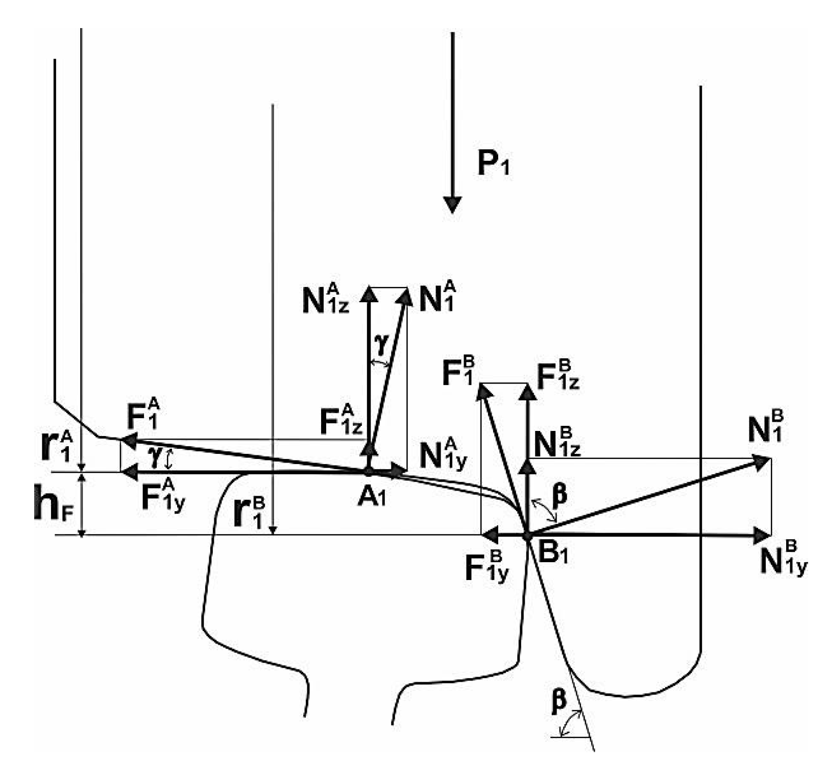
Direction and modulus of the velocity vector of wheel flange slipping on the rail head in the center of the flange contact for the general case of rolling on the rail of the traditional wheel design at the speed VW, with the two-point contact, with an angle of running on the rail ψ in the presence of slippage in the main contact of the wheel, and the rail at the velocity V 1 A , which we will define in the same way as in [3,4,5]. We assume that slippage in the main contact of the wheel and the rail is not related to the application of traction or braking torque to the wheel (wheel of non-traction rail vehicle), rather it is caused specifically by the reactions in connections of the wheel with a bogie. The calculation schemes are shown in Figure 1 and Figure 2.
The diagrams (Figure 1 and Figure 2) use the following designations:
A 1 and B 1 —points denoting the centers of the main and ridge contacts, respectively;
r 1 A and r 1 B —the distance from the axis of rotation of the wheel to the center of the main and ridge contacts, respectively;
ϕ ˙ W —angular speed of rotation of the wheel relative to its own axis of rotation;
V W —the linear speed of the movement of wheel on the rail;
V 1 A —the speed of longitudinal slip in the main contact of the wheel;
h F —vertical displacement of the flange contact relative to the main one;
X F —“Outstripping” of the flange contact.
We assume, the wheel flange contacts the side edge of the rail head at a point located under the main contact level (point A1) by the value hF (hF = 8 ÷ 10 mm) and toward in the direction of motion (so-called “angle to attack”) at the distance XF (XF = 1 ÷ 3 mm).
The flange attack position can be determined by the expression:
X F ( r 1 A + h F ) tan ψ tan β ,
where β is the angle of inclination of the conical part of the wheel flange and r 1 A is the rolling radius of the wheel tread.
The angular velocity φ ˙ W of the wheel rotation about the axis of the wheelset o (axis of rotation o is perpendicular to the plane of the scheme in Figure 1 in the point O) will be calculated as follows:
φ ˙ W = V W ± V 1 A r 1 A .
The point B1 of the flange contact center sliding along the side edge of the rail head makes a complex movement and it tries to turn around the instantaneous rotation center of the wheel (point A1) at the velocity V 1 O (rolling without slipping) and, at the same time, the wheel is slipping along the longitudinal axis of the rail at the velocity V 1 A [26]. The resulting instantaneous center of rotation of the wheel will be at the point C.
The angle χ between the projection V 1 X Z B of the slippage velocity vector V 1 B in the center of the flange contact B1 on the plane xoz in the coordinate system associated with the wheel and the horizontal axis can be determined using the following relation (Figure 1):
χ = arcsin ( x Г | C B 1 | )
The relative wheel slippage on the rail at the center of the main contact point A1 will be
ε = V 1 A V W .
From the geometry shown in the calculating scheme depicted in Figure 1 we can write:
| O C | = r 1 A | A 1 C | ,   | D C | = h F + | A 1 C | ,   | C B 1 | = | D C | 2 + X F 2 ,
ϕ ˙ W = V 1 A / | A 1 C | = V W / | O C | V 1 A V W = ε = | A 1 C | r 1 A | A 1 C |
After transformations of expression (6), we obtain
| A 1 C | = r 1 A ε 1 + ε ,
ϕ ˙ W = V W / | O C | = V 1 X Z B / | C B 1 | V 1 X Z B = V W | C B 1 | / | O C | = V W ( h F + r 1 A ε 1 + ε ) 2 + X F 2 r 1 A ( 1 ε 1 + ε )
Respectively,
χ = arcsin ( X F ( h F + r 1 A ε 1 + ε ) 2 + X F 2 ) .
Analyzing expressions (3) and (6) we can see, that the value of the angle χ and the projection modulus V 1 X Z B slip velocity vector in а flange contact V 1 B is unambiguously determined by the geometric characteristics of the contact between the wheel and the rail, the parameters of their profiles, as well as the value of slippage in the center of the main contact.
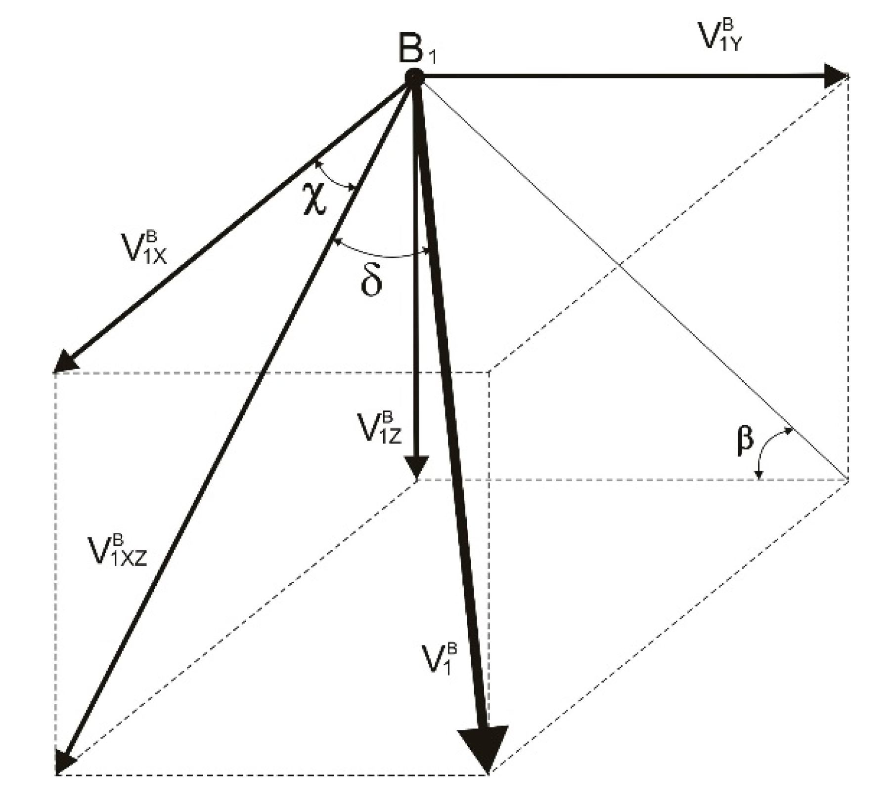
Figure 3 shows the projections of the slip velocity vector V 1 B in the flange contact in the axis of the coordinate system related with the wheel.
Modulus of the corresponding projections of the slip velocity vector V 1 B in the flange contact in the coordinate axis are determined as follows:
V 1 X B = V 1 X Z B cos χ ,   V 1 Y B = V 1 X Z B sin χ tan β ,   V 1 Z B = V 1 X Z B sin χ .
Then
V 1 B = ( V 1 X B ) 2 + ( V 1 Y B ) 2 + ( V 1 Z B ) 2 = V 1 X Z B ( cos χ ) 2 + ( sin χ tan β ) + ( sin χ ) 2 =   = V W ( h F + r 1 A ε 1 + ε ) 2 + X F 2 r 1 A ( 1 ε 1 + ε ) 1 + ( sin χ tan β ) 2
It is obvious, that in this case, the modulus of the vector V 1 B is also unequivocally determined by the geometry of the contact of the wheel and the rail by the longitudinal velocity of the wheel and the level of slip in the main contact.
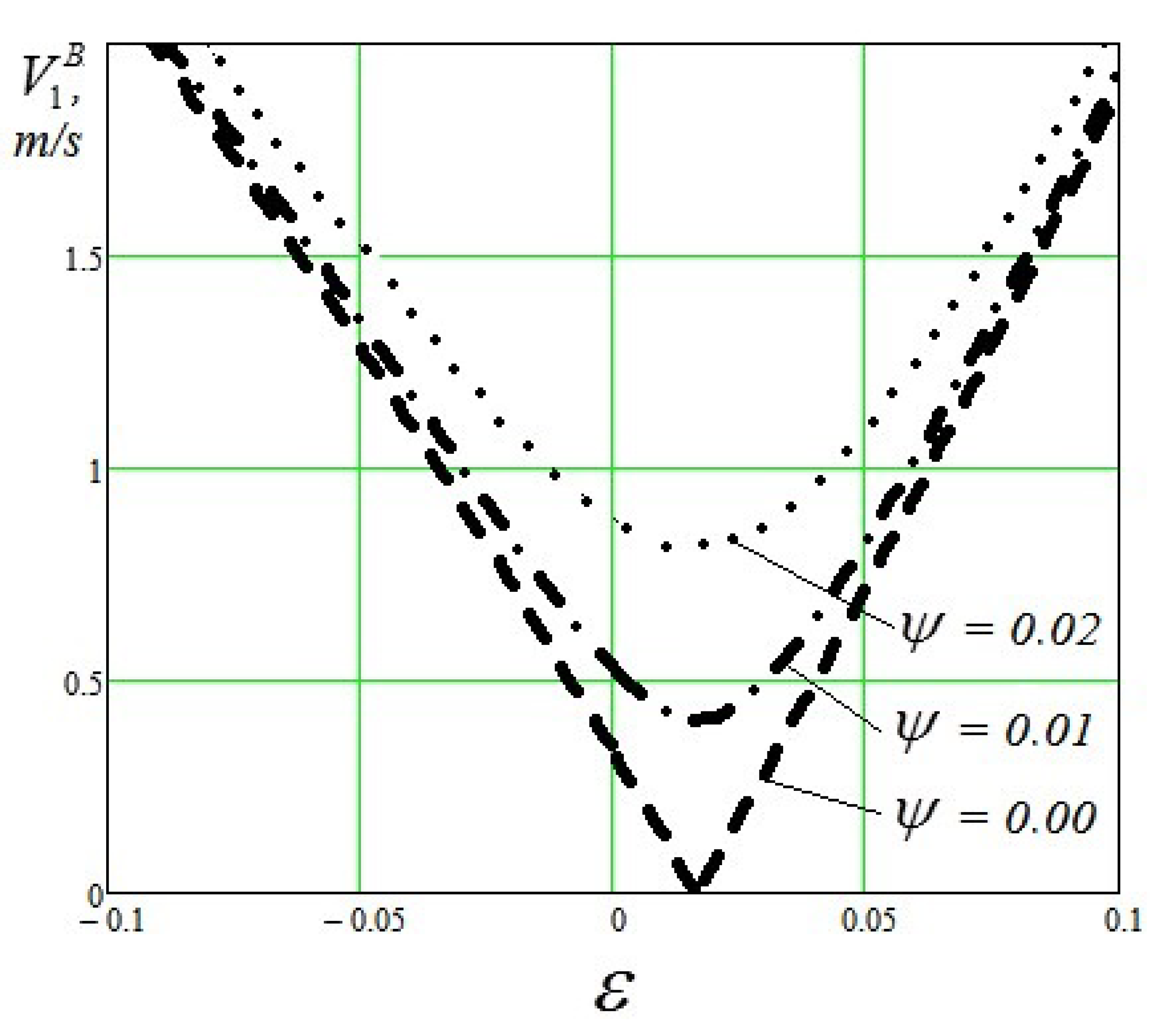
The influence of the level of relative slippage ε in the main contact of the traditional wheel design on the value of the slip velocity in its flange contact for various motion conditions are shown by the graphs depicted in Figure 4. The calculations were carried out for the following values of the variables: V W = 20 m/s, r 1 A = 0.475 m, hF = 0.01 m.
Analyzing the graph shows a significant effect of the level of relative slippage ε in the main contact on the value of the slip velocity V 1 B in the flange contact of the traditional wheel design. This effect is especially noticeable when the wheel moves with small angles to attack on the rail [27,28]. The graph in Figure 4 clearly shows the minimum value V 1 B , which is reached when the value ε ≈ 0.02. This effect is obviously related with the peculiarities of the spatial arrangement of the contact points between the wheel and the rail under the given geometric characteristics and running conditions. For ψ = 0.0 rad, the center of the flange contact coincides with the instantaneous center of the wheel rotation.

2.2. Description of the Wheel Movement with a Perspective Wheel Design

Let us consider how the character of slip in the flange contact will change when the possibility of independent rotation of the wheel tread and the wheel flange around their axis of rotation o-у will be realized (perspective wheel design). To do this, in a similar way, we define the direction and the modulus of the wheel flange velocity vector sliding on the rail V 1 B A in the center of the flange contact under the same motion conditions as in the previous case (for the traditional wheel design).
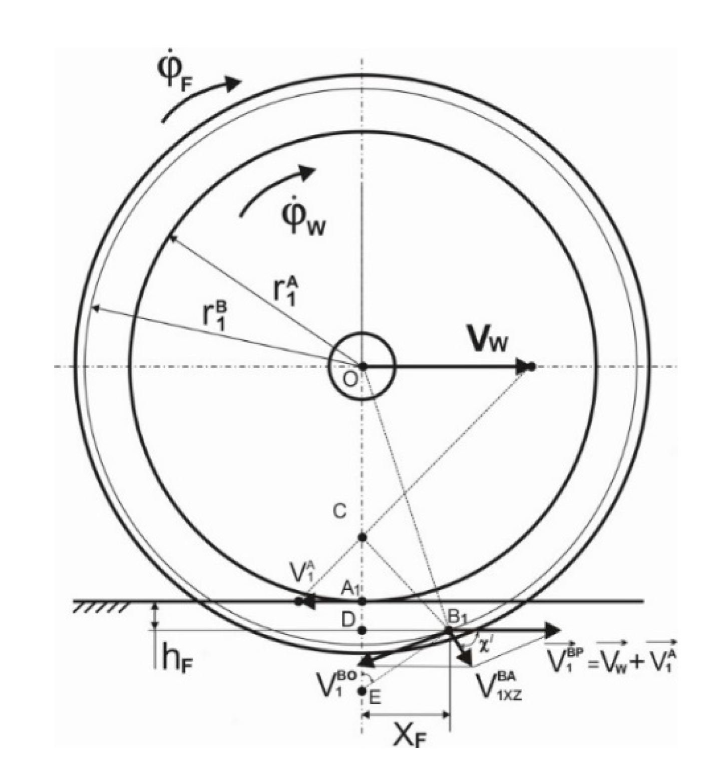
The calculation scheme for this case is shown in Figure 5. We find location of the flange contact center with the side face of the rail head at a point B1 (values hF and XF) in the same way as in the previous case.
In the diagram in Figure 5: ϕ ˙ F —the angular speed of rotation of the guide surface (flange) relative to the axis of rotation of the wheel.
For determining the direction of the velocity vector V 1 B A , it is necessary to take into account that the guiding surface of the wheel (flange) participates in a complex movement together with the wheel tread surface of the wheel. The carrying velocity at the center of the flange contact point B1 will be V 1 B P = V W ± V 1 A .
At the same time, the point B1 of the flange contact center is in relative motion at the velocity V 1 B O about the common rotation axis o-y the wheel tread surface and its flange passing through the point O along the normal direction to the plane of the scheme shown in Figure 5.
We will find the direction and the modulus of the projection vector the velocity V 1 X Z B A in the coordinate system related with the wheel flange point B1 movement:
V 1 X Z B A = V 1 B P + V 1 B O .
From the condition, that the conditional center of the flange moves at the velocity V W ± V 1 A together with the geometric center of the wheel tread surface, we find the position of the instantaneous center of flange rotation E in the intersection of normals of the velocity vectors V W and V 1 X Z B A , which are held in their points of application. In this case, the angle χ′ between the vector of the projection of the absolute slip velocity in the center of the flange contact V 1 X Z B A on the rolling plane of the wheel and the horizontal plane is determined by the formulation:
χ / = arcsin ( X F | E B 1 | ) .
where
| E B 1 | = | E D | 2 + X F 2 .
From the analysis of the calculation scheme in Figure 5 it follows, that
| E D | = V W φ ˙ F r 1 A h F   and   V W = φ ˙ k r 1 A ( 1 + ε ) .
Then,
χ / = arcsin { X F [ ( φ ˙ W φ ˙ F ( 1 + ε ) 1 ) r 1 A h F ] 2 + X F 2 } =   = arcsin { ( r 1 A + h F ) tan ψ tan β [ ( φ ˙ W φ ˙ F ( 1 + ε ) 1 ) r 1 A h F ] 2 + [ ( r 1 A + h F ) tan ψ tan β ] 2 } .
The modulus of the velocity V 1 X Z B A will be determined when considering the calculation scheme in Figure 5 as follows:
  • From one side:
    ϕ ˙ F = V 1 X Z B A | E B 1 | ,
  • From the opposite side:
    ϕ ˙ F = V W | E O | .
    where
    | E O | = r 1 A + h F + | E D | ,
Then we can write:
V 1 X Z B A | E B 1 | = V W | E O | ,
After simple transformations we get:
V 1 X Z B A = V W | E D | 2 + X F 2 r 1 A + h F + | E D | ,
By considering (1) and (15) we get:
V 1 X Z B A = V W [ ( φ ˙ F φ ˙ W φ ˙ F ( 1 + ε ) 1 ) r 1 A h F ] 2 + X F 2 φ ˙ W φ ˙ F ( 1 + ε ) r 1 A = = φ ˙ F [ ( φ ˙ W φ ˙ F ( 1 + ε ) 1 ) r 1 A h F ] 2 + [ ( r 1 A + h F ) tan ψ tan β ] 2 .
Using expressions similar to expressions (10) we can write:
V 1 B A = ( V 1 X B A ) 2 + ( V 1 Y B A ) 2 + ( V 1 Z B A ) 2 = V 1 X Z B A ( cos χ / ) 2 + ( sin χ / tan β ) 2 + ( sin χ / ) 2 = = φ ˙ F [ ( φ ˙ W φ ˙ F ( 1 + ε ) 1 ) r 1 A h F ] 2 + [ ( r 1 A + h F ) tan ψ tan β ] 2 1 + ( sin χ / tan β ) 2 .
Obviously, if there is a constructive possibility of turning of the flange relative to the wheel tread surface, then the angle χ′ of inclination to the horizontal plane of the projection V 1 X Z B A of slip velocity vector of the flange on the rail and the modulus of this vector will also depend on the ratio of the angular velocity of the wheel rotation and the flange.
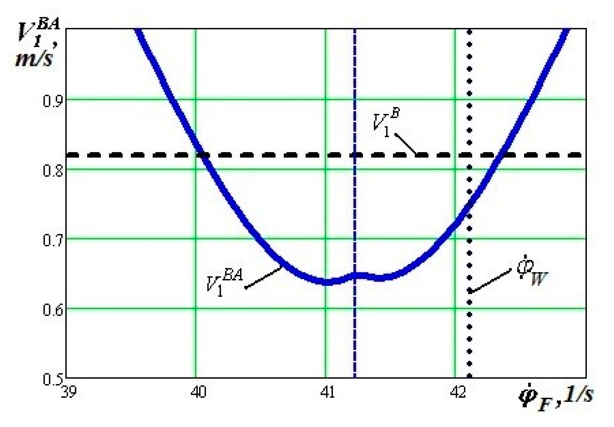
Given the values φ ˙ F at a fixed value φ ˙ W and ε, one can obtain the corresponding values of the angle χ′ (Figure 6) and the modulus of the velocity vector V 1 B A (Figure 7).
When we analyze the graph shown in Figure 6, we can see that the value of the angle χ′ is relatively small, essentially in the entire considered range of values of angular velocity φ ˙ F and only at values φ ˙ F φ ˙ W r 1 A r 1 B at the given longitudinal velocity of the wheel, the value of the angle χ′ → π/2. In this case, the projection of the slip velocity vector V 1 X Z B A of the flange along to the side edge of the rail head onto the rolling plane of the wheel directs perpendicularly to the horizontal direction and the modulus of this vector reaches the minimum value. For example, for the angle to attack ψ = 0.015, ε = 0.01, and r 1 A = 475 mm, the ratio r 1 A / r 1 B is of 0.979. With the indicated ratio of the angular velocities of the tread surface and the flange of the wheel, the linear longitudinal velocity of movement of the main centers and the flange contacts can be considered approximately equal, when the wheel is rolling at a constant linear velocity VW = 20 m/s.
From the graph depicted in Figure 7 it can be seen, that at χ′ = π/2 for the given running conditions, the value of the slip velocity in the flange contact V 1 B A is small, but it does not equal to zero.
Analyzing the expression (19), it is possible to determine the possible modes of the wheel motion, in which V 1 B A → 0. Obviously, this must simultaneously meet the conditions XF → 0 and |ED| → 0.
The value XF = 0 is achieved, when the approach angle ψ wheels on rail, it equals to zero.
As | E D | = ( φ ˙ W φ ˙ F ( 1 + ε ) 1 ) r 1 A h F , that the condition |ED| → 0 can be performed (with a fixed value φ ˙ W ) when:
φ ˙ F = φ ˙ W ( h F r 1 A + 1 ) ( 1 + ε ) = φ ˙ W K w * ,
where
K w * = ( h F r 1 A + 1 ) ( 1 + ε ) ,
Considering the values h F , ε and r 1 A , we get the value K w * = 1.031 and its possible changes can be neglected. It means, that in the given mode of the wheel rotation with the perspective wheel design, there is a possibility of the absence of the kinematic slip in the flange contact, i.e., the velocity V 1 B A = 0 m/s and it can happen for ψ = 0.00 rad and ϕ ˙ F = 0.97 ϕ ˙ W .
The graph of dependency function K w * = f ( ε ) is shown in Figure 8.
The calculated results shows that the level of slippage in the main contact of the railway wheel with the perspective wheel design with the rail influences the value of the optimal ratio of angular velocities of the wheel tread surface and its flange. This influence is quite insignificant—in the considered range of relative slippage ε variation in the indicator K w * it does not exceed 5%.

3. Results and Discussion of the Research

Figure 9 shows the graphs of function dependency V 1 B A = f ( φ ˙ F , ε ) , which demonstrates the characteristics of the influence level of the relative slippage ε in the main contact of the wheel with the rail due to the value V 1 B A , when the wheel is rotating at a speed VW = 20 m/s and with angles to attack ψ = 0.00 rad and ψ = 0.02 rad.
Analyzing the graphs depicted in Figure 9 we can also confirm the insignificant influence of the level of the relative slip ε in the main contact on the value of the slip velocity V 1 B A in the flange contact of the railway wheel of the perspective constructive scheme.
When we take into account the absence of strict restrictions on the value of the angular velocity of the movable flange in the wheel with the perspective wheel design, the stationary state of the considered mechanical system can be determined. We use the well-known principle of the minimum entropy of the system (the minimum energy dissipation). This principle states that if not a single state of the system is permissible, but a certain set of states consistent with conservation laws and constraints imposed on the system, then its state is realized, which corresponds to the minimum increase in the entropy of the system or, which is the same, the minimum energy dissipation.
Therefore, we can consider, that the quasi-static state (steady state) of the investigated system (a wheel with a movable flange interacting with a rail) is its state, in which the energy dissipation in the flange contact is minimal [4].
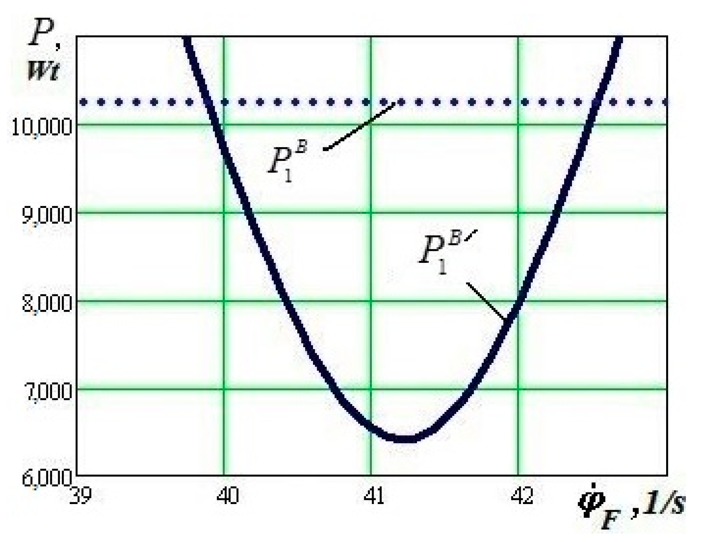
When we want to assess the effectiveness of the perspective wheel design from the reducing the kinematic resistance to movement point of view, we have to determine how much the power of friction forces in the flange contact can be reduced using these wheel design.
The value of the instantaneous power of the friction forces is usually represented as the scalar quantity of the friction force vector in the flange contact B1 and the vector of the corresponding instantaneous sliding velocity of the flange point B1 on the rail.
When we take into account the fact that the friction force vector is directly opposite to the vector of the corresponding instantaneous velocity, i.e., δ = π and cosπ = −1, in our case, the magnitude of the power of friction forces in the flange contact when using the traditional constructive scheme P 1 B and the perspective constructive scheme of the wheel P 1 B / can be determined, respectively, from the expressions (26), (27):
P 1 B = | F 1 B V 1 B | ,
P 1 B / = | F 1 B / V 1 B A | ,
Some calculation results are shown in Figure 10, where graphs of the function dependencies V 1 B = f ( φ ˙ F ) and V 1 B A = f ( φ ˙ F ) at the velocity VW = 20 m/s, F 1 B = 12,500 N, ε = 0.01 and ψ = 0.015 rad are depicted. There is noticeable decrease of the friction forces power dissipated in the flange contact of the perspective wheel design in comparison with the traditional wheel design for the given running conditions in the range of angular velocities of the flange 39.8 rad/s < φ ˙ F < 42.5 rad/s.
Analyzing these dependencies graphs we identify, that when the perspective wheel design is applied, it is possible to reduce the friction forces power dissipated in the flange contact to 60% for a certain ratio of the angular velocities of the wheel tread surface and its flange for given running conditions.
Although the presented technical solution does not allow such a significant relative rotation of the wheels on the same axle relatively to each other as it is in the case of using independently rotating wheels described above, it does combine advantages of the traditional wheelset with wheels pressed on an axle with advantages of independently rotating part of the wheel flange, which reduces negative effects related with rail vehicle running through curves with small radii [29].
Clarification of the features of the movement of wheels with various designs on the rail with two-point contact points taking into account slippage in the main contact, made it possible to specify the following:
  • The level of slippage in the main contact of the perspective wheel design insignificantly influences the value of slippage speed in its flange contact. For the traditional wheel design, this effect is more significant
  • The results of the calculations confirm the possibility of a significant reduction of the slip rate in the flange contact for the perspective wheel design compared with the traditional wheel design. This gives reason to expect a reduction of the corresponding friction forces power in these contacts and a reduction of the resistance to move the rail vehicles if they were equipped with wheels with the perspective wheel design, especially when they move in curved sections of a railway track
In further research, a great effort is to proceed in the study by creating a model of the presented technical solution of the wheel with the perspective wheel design in MBS software [30,31,32,33]. A created model will allow us to compare dynamic properties of a wheelset or a rail vehicle equipped with wheels with the traditional wheel design with dynamic properties of a rail vehicle, whose wheels the perspective wheel design will be used on. In MBS software, it will also be possible to define the real geometry of a track, including track irregularities [34], to change appropriate parameters, such as running speed, radius diameters, etc. In this way, it will be possible to verify the achieved presented results. We suppose, the calculation of the contact surface of the wheel will be different, because for the two-point contact, i.e., the wheel tread and the flange, a relative motion of these two contact points will occur. The objective of the research will be to investigate, whether it will be possible, and with what reliability, we can apply known algorithms for calculation of the wheel/rail contact [35,36,37]. Furthermore, the research will continue in terms of studying of structural properties of the perspective wheel design. It is obvious, the distribution of stress, as well as heat in the wheel with the perspective design, will be significantly different in comparison with the wheel with the traditional design [38,39,40]. Undoubtedly, attention should also be paid to the issues of traffic safety of rail vehicles with wheels of the perspective constructive scheme [41].

4. Conclusions

The features of the spatial geometry of the wheel/rail contact related with the traditional wheel de-sign cause forced kinematic slippage in the contact point of the wheel flange with the side edge of the rail head in case of a two-point contact.
In the article, features of rolling of wheels with the traditional wheel design and with the perspective wheel design including slippage in main contact were considered. The perspective constructive scheme of the wheel allows the independent relative rotation of the support surface of the wheel and of its guiding surface, i.e., of its flange, relatively to their common axis of rotation.
The study showed that the level of slippage in the main contact of the wheel with the perspective wheel design insignificantly influences the value of the slip velocity in its flange contact. For the traditional wheel design, this influence is more significant.
The calculations confirm the possibility of a significant reduction of the slip velocity in the flange contact, and accordingly, the reduction of the friction force power in the contact of the rail and the wheel with the perspective wheel design in comparison with the traditional wheel design; this includes when driving with slippage in the main contact. The results obtained confirm the possibility of reducing the resistance to movement of rail vehicles with wheels of a perspective constructive scheme.

Author Contributions

Conceptualization, S.S. and S.K.; methodology, E.M., S.S., M.K., and M.B.; software, E.M., J.G., and J.H.; validation, S.S., J.D., J.G., and M.K.; investigation, E.M., S.S., J.G., and M.K.; resources, S.S., J.D., and J.H.; writing—original draft preparation, S.S., S.K., and J.D.; writing—review and editing, E.M., M.B., and J.H.; supervision, E.M. and J.G.; funding acquisition, J.D., M.B., J.G., and J.H. All authors have read and agreed to the published version of the manuscript.

Funding

This research was supported by the Cultural and Educational Grant Agency of the Ministry of Education of the Slovak Republic in the project No. KEGA 023ŽU-4/2020: Development of advanced virtual models for studying and investigation of transport means operation characteristics and by the Slovak Research and Development Agency of the Ministry of Education, science, Research and Sport of the Slovak Republic in Educational Grant Agency of the Ministry of Education of the Slovak Republic in the project No. VEGA 1/0558/18: Research of the interaction of a braked railway wheelset and track in simulated operational conditions of a vehicle running in a track on the test bench.

Conflicts of Interest

The authors declare no conflict of interest.

References

  1. Tkachenko, V.P.; Sapronova, S.J.; Fomin, O.V.; Kul’bovs’kij, I.I.; Zub, E.P. Movement Resistance and Control-Lability of Rail Vehicles; Monograph: Kiev, Ukraine, 2017; p. 188. (In Ukrainian) [Google Scholar]
  2. Tkachenko, V.P. Kinematic Resistance to the Movement of Rail Vehicles; VUGU: Lugansk, Ukraine, 1996; p. 200. (In Russian) [Google Scholar]
  3. Mikhailov, E.; Semenov, S.; Panchenko, E. The possibility of reducing kinematic slip with two-point contacting with rail wheel railway vehicle. TEKA Komisji Motoryzacji i Energetyki Rolnictwa 2013, 13, 139–145. [Google Scholar]
  4. Mikhailov, E.; Semenov, S.; Tkachenko, V.; Sapronova, S. Reduction of Kinematic Resistance to Movement of the Railway Vehicles. MATEC Web Conf. 2018, 235. [Google Scholar] [CrossRef]
  5. Mikhailov, E.; Semenov, S.; Dižo, J.; Kravchenko, K. Research of possibilities of reducing the driving re-sistance of a railway vehicle by means of the wheel construction improvement. Transp. Res. Procedia 2019, 40, 831–838. [Google Scholar] [CrossRef]
  6. Simson, S.A.; Pearce, M.E. Wheel wear losses from bogie rotation resistance, effects of cant and speed. In Proceedings of the Joint Rail Conference on Restoring and Upgrading Rail Infrastructure, Rolling Stock and Systems, Atlanta, GA, USA, 4–6 April 2006. [Google Scholar]
  7. Efficiency of Rail Lubrication. Railways of the World. Available online: http://www.railsystem.net/rail-wheel-lubrication/ (accessed on 26 September 2020).
  8. Masliev, V.G. Locomotive Dynamics with Devices That Reduce Railway Wheel Wear; NTU: Kharkiv, Ukraine, 2008; p. 288. (In Russian) [Google Scholar]
  9. Liang, B.; Iwnicki, S.D. An Experimental Study of Independently Rotating Wheels for Railway Vehicles. In Proceedings of the International Conference on Mechatronics and Automation, Harbin, China, 5–8 August 2007. [Google Scholar]
  10. Pombo, J.A.; Ambrósio, M.S. New wheel-rail contact model for railway dynamics. Veh. Syst. Dyn. 2007, 45, 165–189. [Google Scholar] [CrossRef]
  11. Ma, Y.; Markine, V.; Mashal, A.A.; Ren, M. Modelling verification and influence of operational patterns on tribological behaviour of wheel-rail interaction. Tribol. Int. 2017, 114, 264–281. [Google Scholar] [CrossRef] [Green Version]
  12. Masek, J.; Kendra, M.; Milinkovic, S.; Veskovic, S.; Barta, D. Proposal and Application of Methodology of Revitalisation of Regional Railway Track in Slovakia and Serbia. Part 1: Theoretical Approach and Proposal of Methodology for Revitalisation of Regional Railways. Transp. Probl. 2015, 10, 85–95. [Google Scholar] [CrossRef] [Green Version]
  13. Seo, S.I.; Mun, H.S. Development of technologies for mountain trams driven through sharp curves. J. Mech. Sci. Technol. 2019, 33, 2019–2027. [Google Scholar] [CrossRef]
  14. Ilgakojyte-Bazariene, J.; Lebeckas, J.; Kersys, R. Quality of Public Transport Service in Kaunas. In Proceedings of the Transport Means 2016 Conference, Juodkrante, Lithuania, 5–7 October 2016. [Google Scholar]
  15. Leitner, B.; Mocova, L.; Hromada, M. A new Approach to Identification of Critical Elements in Railway Infrastructure. Procedia Eng. 2017, 187, 143–149. [Google Scholar] [CrossRef]
  16. Dvorak, Z.; Leitner, B.; Novak, L. Software Support for Railway Traffic Simulation under Restricted Conditions of the Rail Section. Procedia Eng. 2016, 134, 245–255. [Google Scholar] [CrossRef] [Green Version]
  17. Stastniak, P.; Smetanka, P. Study of a Railway Wheel Running Surface Wear by Using of Simulation Tools. In Proceedings of the 24th International Conference on Current Problems in Rail Vehicles, Zilina, Slovakia, 17–19 September 2019. [Google Scholar]
  18. Melnik, R.; Sowinski, B. Analysis of Dynamics of a Metro Vehicle Model with Differential Wheelsets. Transp. Probl. 2017, 12, 113–124. [Google Scholar] [CrossRef] [Green Version]
  19. Kostrzewski, M.; Melnik, R. Numerical dynamics study of a rail vehicle with differential gears. Procedia Eng. 2017, 192, 439–444. [Google Scholar] [CrossRef]
  20. Lu, Z.G.; Yang, Z.; Huang, Q.; Wang, X.C. Robust active guidance control using the mu-synthesis method for a tramcar with independently rotating wheelsets. Proc. Inst. Mech. Eng. Part F J. Rail Rapid Transit 2019, 233, 33–48. [Google Scholar] [CrossRef]
  21. Datoussaid, S.; Verlinden, O.; Wenderloot, L.; Conti, C. Computer-aided analysis of urban railway vehicles. Veh. Syst. Dyn. 1998, 30, 213–227. [Google Scholar] [CrossRef]
  22. Ji, Y.J.; Ren, L.H.; Zhou, J.S. Boundary Conditions of Active Steering Control of Independent Rotating Wheelset Based on Hub Motor and Wheel Rotating Speed Difference Feedback. Veh. Syst. Dyn. 2018, 56, 1883–1898. [Google Scholar] [CrossRef]
  23. Hauser, V.; Kravchenko, K.; Nozhenko, O.; Fomin, A. Tram Car Bogie Concept and Consideration of his Impact to the Track. In Proceedings of the 24th International Conference on Current Problems in Rail Vehicles, Zilina, Slovakia, 17–19 September 2019. [Google Scholar]
  24. Nozhenko, O.; Hauser, V.; Kravchenko, K.; Loulova, M. Proposal of Wheel with Additional Tread for Vehicle to Strongly Curved Track Interaction Improvement. In Proceedings of the 23rd Conference: Current Problems in Rail Vehicles 2017, Ceska Trebova, Czech Republic, 20–22 September 2017. [Google Scholar]
  25. Shiler, A. Analysis and Simulation of New Wheel Pair Construction. Procedia Eng. 2015, 100, 1714–1723. [Google Scholar] [CrossRef]
  26. Mikhailov, E.; Semenov, S.; Sapronova, S.; Tkachenko, V. On the Issue of Wheel Flange Sliding along the Rail. In Lecture Notes in Intelligent Transportation and Infrastructure; Springer: Berlin/Heidelberg, Germany, 2020; pp. 377–385. [Google Scholar]
  27. Gerlici, J.; Lack, T. Wheelset/Rail Geometric Characteristics and Contact Forces Assessment with Regard to Wheelset Rolling. MATEC Web Conf. 2019, 254. [Google Scholar] [CrossRef]
  28. Lack, T.; Gerlici, J.; Stastniak, P. Wheelset/Rail Geometric Characteristics and Contact Forces Assessment with Regard to Angle of Attack. MATEC Web Conf. 2019, 254. [Google Scholar] [CrossRef]
  29. Gerlici, J.; Tkachenko, V.; Sapronova, S.T.; Lack, T. Steerability Research of Railway Vehicles. In Proceedings of the 24th International Conference on Current Problems in Rail Vehicles, Zilina, Slovakia, 17–19 September 2019. [Google Scholar]
  30. Sapietova, A.; Gajdos, L.; Dekys, V.; Sapieta, M. Analysis of the Influence of Input Function Contact Parameters of the Impact Force Process in the MSC. ADAMS. Adv. Mechatron. Solut. 2016, 393, 243–253. [Google Scholar]
  31. Skocilasova, B.; Skocilas, J.; Klimenda, F.; Soukup, J.; Handrik, M. Vertical Oscillation Investigation of Spatially Elastically Supported Rigid Plate—Vehicle Model. MATEC Web Conf. 2019, 254. [Google Scholar] [CrossRef]
  32. Skvireckas, R.; Kersys, A.; Kersys, R.; Lukosevicius, V. Research of lateral vibrations of a passenger wagon running along the curved path. J. Vibroeng. 2012, 14, 706–714. [Google Scholar]
  33. Steisunas, S.; Bureika, G. Study of Freight Wagon Running Dynamic Stability Taking into Account the Track Stiffness Variation. Transp. Probl. 2014, 9, 131–143. [Google Scholar]
  34. Saga, M.; Jakubovickova, L. Simulation of Vertical Vehicle Non-Stationary Random Vibrations Con-sidering Various Speeds. Sci. J. Sil. Univ. Technol. 2014, 84, 113–118. [Google Scholar]
  35. Baeza, L.; Thompson, D.J.; Squicciarini, G.; Denia, F.D. Method for Obtaining the Wheel-Rail Contact Location and its Application to the Normal Problem Calculation through “CONTACT”. Veh. Syst. Dyn. 2018, 56, 1734–1746. [Google Scholar] [CrossRef]
  36. Bizic, M.B.; Petrovic, D.Z.; Tomic, M.C.; Djinovic, Z.V. Development of method for experimental determination of wheel-rail contact forces and contact point position by using instrumented wheelset. Meas. Sci. Technol. 2017, 28, 75902. [Google Scholar] [CrossRef]
  37. Stastniak, P.; Moravcik, M.; Baran, P.; Smetanka, L. Computer aided structural analysis of newly developed railway bogie frame. MATEC Web Conf. 2018, 157. [Google Scholar] [CrossRef] [Green Version]
  38. Suchanek, A. Measuring and Calculation of Residual Stresses in a Railway Wheel. In Proceedings of the XXIV 24th International Conference on Current Problems in Rail Vehicles, Zilina, Slovakia, 17–19 September 2019. [Google Scholar]
  39. Klebanov, I.M.; Kuraeva, Y.V. Finite Element Analysis of Railway Wheel-Rail Contact Interaction. Vestn. Samar. Gos. Tekhnicheskogo Univ. Seriya Fiz. Mat. Nauk. 2008, 1, 59–62. [Google Scholar]
  40. Milosevic, M.S.; Stamenkovic, D.S.; Milojevic, A.P.; Tomic, M.M. Modeling Thermal Effects in Braking Systems of Railway Vehicles. Therm. Sci. 2012, 16, 515–526. [Google Scholar] [CrossRef]
  41. Dindar, S.; Kaewunruen, S. Assessment of turnout-related derailments by various causes. In Proceedings of the International Congress and Exhibition Sustainable Civil Infrastructures: Innovative Infrastructure Geotechnology GeoMEast 2017, Sharm Elsheikh, Egypt, 15–17 July 2017. [Google Scholar]
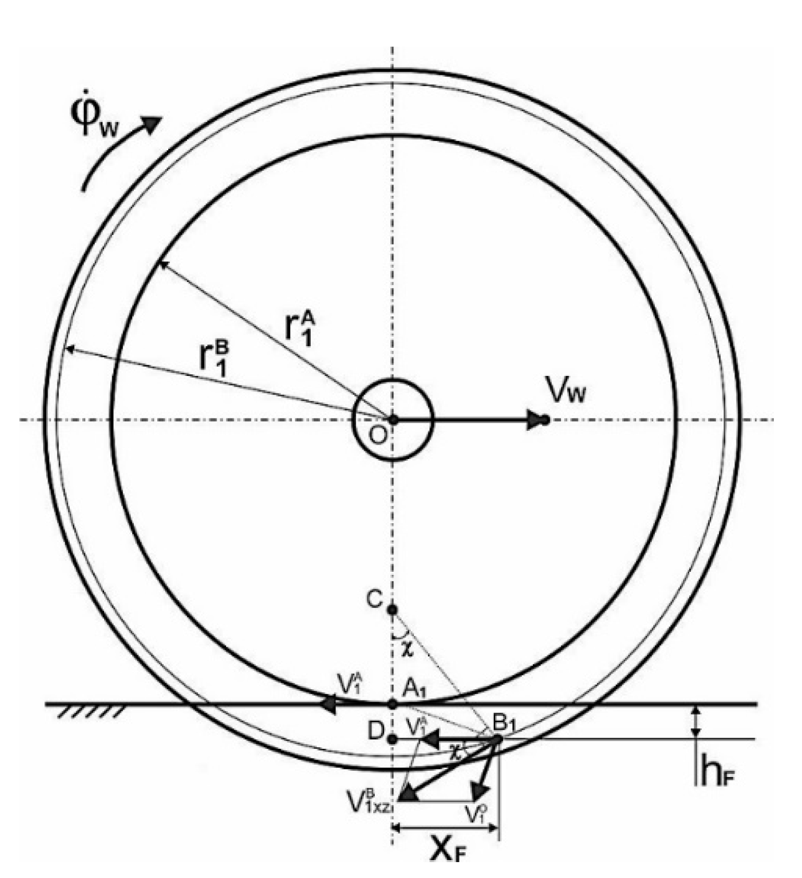
Figure 1. A calculation scheme—side view, the traditional wheel design.
Applsci 10 06758 g001
Figure 2. A calculation scheme—front view, the traditional wheel design.
Applsci 10 06758 g002
Figure 3. A calculation scheme—front view, the traditional wheel design.
Applsci 10 06758 g003
Figure 4. Graph of dependency of the slip velocity V 1 B on the relative slippage V 1 B = f ( ε , ψ ) , the traditional wheel design.
Applsci 10 06758 g004
Figure 5. A calculation scheme—side view, the perspective wheel design.
Applsci 10 06758 g005
Figure 6. Example of dependency of the angle χ′, χ / = f ( φ ˙ F ) at the speed VW = 20 m/s and for ε = 0.01 and ψ = 0.015 rad.
Applsci 10 06758 g006
Figure 7. Example of dependency of the velocity V 1 B A , V 1 B A = f ( φ ˙ F ) , the speed at VW = 20 m/s and for ε = 0.01 and ψ = 0.015 rad.
Applsci 10 06758 g007
Figure 8. Graph of the function dependency K w * = f ( ε ) .
Applsci 10 06758 g008
Figure 9. Graphs of function dependency V 1 B A = f ( φ ˙ F , ε ) , (a) ψ = 0.00 rad, (b) ψ = 0.02 rad.
Applsci 10 06758 g009
Figure 10. Graph of functional dependency P 1 B = f ( ϕ ˙ Γ ) and P 1 B / = f ( ϕ ˙ F ) (running conditions: VW = 20 m/s, F 1 B = 12,500 N, ε = 0.01 and ψ = 0.015 rad).
Applsci 10 06758 g010