1. Introduction
One of the highest challenges for future wireless communication systems is to ensure the support for massive data traffic, while maintaining a low communication latency [
1,
2,
3,
4,
5], support needed due to the continuous evolution of multimedia applications and a rapidly growing number of users that request simultaneously access to different network resources from everywhere and anytime while maintaining a good quality of service (QoS) as well as a high flexibility with respect to individual user requirements. A promising technique envisioned to accomplish the above-mentioned demands and also provide a superior spectral efficiency is nonorthogonal multiple access (NOMA) that has been included in the new 5G standard [
6,
7,
8,
9,
10,
11].
An orthogonal multiple access (OMA) scheme assumes the use of a perfect receiver that makes a complete separation of the unwanted signals from the desired one, meaning that signals coming from different users are orthogonal to each other, either in time, frequency, or code domains [
12,
13,
14]. Important to mention is that the orthogonality condition is effective when the system is underloaded, meaning that the number of active users is lower than the number of block resources (the number of degrees of freedom) [
15,
16]. A few examples of radio access technologies that fit within the OMA definition are time division multiple access (TDMA), frequency division multiple access (FDMA), code division multiple access (CDMA), and orthogonal frequency division multiple access (OFDMA).
OMA can accommodate only a single user within the same time/frequency resource block to cancel any user interferences (for example, TDMA, FDMA, and OFDMA; but CDMA allows multiple users to be served within the same resource block using a unique spreading sequence for each user in order to separate them) [
17]. OMA also offers satisfactory performance regarding the inter-user interference (IUI), but it can be overlooked if IUI can be kept under normal standards using other domains [
15,
18]. By contrast, NOMA supports multiple users that can be served in the same time and frequency resource block, within the same cell, multiplexed in the power domain or code domain, typically used to suppress IUI [
4,
7].
The code domain NOMA schemes perform user multiplexing in code domain using a unique spreading sequence for each user with sparse, low-density, and low intercorrelation properties. As long as the orthogonality property is not available, these schemes offer grant-free access, but IUI is present; thus, at least from these aspects, these schemes can be perceived as an involution if compared with CDMA [
15,
16]. A couple of best-known code domain NOMA schemes are low-density signature (LDS) sequence-based CDMA [
16] and interleave division multiple access (IDMA) [
19]. Other closely related schemes are lattice partition multiple access (LPMA) [
20], sparse code multiple access (SCMA) [
21,
22], multiuser shared access (MUSA) [
23], resource spread multiple access (RSMA) [
24], and pattern division multiple access (PDMA) [
25,
26]. In [
27], the authors make a comparison between IDMA, RSMA, PDMA, and MUSA, taking into account the multiplexing domain, user overload, receiver type, receiver complexity, and grant-free transmission (each user can choose freely its spreading code), reaching the conclusion that MUSA offers a favorable balance between performance and complexity—high user overload and low implementation complexity, and it provides flexibility in grant-free transmissions.
Although orthogonal multiplexing offers a satisfactory performance regarding the throughput level in packet-domain services with a simple design of the receiver [
28], future improvements are required and accomplished by nonorthogonal multiplexing, achieving a better efficiency of the system, achieving the capacity region of the downlink broadcast channel [
29,
30]. Note that NOMA can be applied also on the uplink channel [
29,
30,
31] and together with OMA achieves the capacity region, but NOMA offers an enhancement regarding the trade-off between the capacity of the system and the user-fairness which is important in a cellular system when the channel conditions are different for different users because of the near–far effect [
32].
In this paper, we are going to study the performance of an uplink system that employs a NOMA scheme, namely MUSA, in conjunction with massive multiple input multiple output (MIMO) techniques.
In an uplink MUSA system, the symbols of each user are being spread, using a complex spreading sequence, before transmitting by means of “shared access”, basically meaning a superposition process. Multiple spreading sequences form a pool from which a user can randomly choose one, but for the same user, different spreading sequences can be used, also randomly picked, for each transmitted symbol. The spreading sequences have short lengths which are more efficient in conjunction with successive interference cancellation (SIC) used at the receiver to separate superimposed symbols and low cross-correlation properties and they can be nonbinary [
7,
33,
34,
35].
Paper [
36] presents the performance of MUSA by comparison with two other NOMA schemes, namely SCMA and PDMA, in terms of BER versus SNR. The data were quadrature phase-shift keying (QPSK)-modulated and transmitted over a channel affected by Rayleigh fading and SIC detector at the receiver. The authors concluded that SCMA obtained better performance due to the optimal design of codebooks while MUSA and PDMA had similar performance in the given simulation scenario. The authors in [
37] evaluated the performance of MUSA spreading codes by comparison with pseudo-random noise (PN) with different user overloading but when turbo coding of rate ½ and QPSK modulation were used in an additive white Gaussian noise (AWGN) channel with MMSE-SIC detector at the receiver. The scenario with one antenna at the transmitter and one or two antennas at the receiver has been considered. The authors demonstrated that the block error rate (BLER) of MUSA compared to Long Term Evolution (LTE) standard does not have an important degradation even if the overload is high; also, grant-free MUSA can support higher traffic than grant-free OFDMA. Paper [
38] presents a grant-free MUSA transmission that can achieve high overloading, with 4 to 20 users, where the data are turbo-coded at rate ½ and binary phase shift keying (BPSK)-modulation. The scenario with one antenna at the transmitter and two antennas at the receiver was analyzed, and the reception used a blind minimum mean square error - successive interference cancellation (MMSE-SIC) detector. Similarly, [
39] proposes a high-overloaded autonomous grant-free MUSA transmission with 4 to 16 users, where the data is turbo-coded at rate ½ and BPSK-modulated and introduced in an OFDM block, then sent over a channel affected by flat fading. The system with one antenna at the transmitter and one antenna at the receiver was taken into consideration, and a blind multiuser detection (MUD) without reference signal was used at the receiver. Authors in [
40] propose another high-overloaded autonomous grant-free MUSA transmission with 8 to 20 users, where the data is turbo-coded of rate ½ and BPSK-modulated and sent over a channel affected by flat fading. The scenario with one antenna at the transmitter and two antennas at the receiver was considered and a MUD detector with spatial combining was used at the receiver. In [
41], the performance of a system which employs MUSA with two other NOMA techniques, namely SCMA and IDMA, was evaluated. A turbo channel coding was performed, then data from 12, 16, and 24 users were QPSK-modulated and entered in an OFDM block after which they were transmitted over a channel affected by Rayleigh fading. At the reception, a MMSE detector was used. The scenario with one antenna at the transmitter and one antenna at the receiver was considered. In [
42] the authors present the bit error rate performance of an uplink MUSA transmission with binary, 3-ary, and 5-ary codes where data from six users were QPSK-modulated and then sent over a channel affected by Rayleigh fading. At the reception, an MMSE-ordered SIC detector was used. In [
43], the authors compared, theoretically and numerically, the performance of a 12-user grant-free MUSA transmission with low detection complexity by employing SIC with OFDMA, SDMA-based OFDMA, LDS, and SCMA on the uplink. A low-density parity-check (LDPC) encoder block was used, followed by QPSK modulation and OFDM blocks, the information being transmitted over a channel with AWGN. It was observed that MUSA offers better results for high SNR values and high number of overlapping users. The authors present, in [
44], a high-overloaded autonomous grant-free MUSA transmission with 8 to 20 users, where the data were LDPC-encoded and BPSK-modulated and sent over a channel affected by deep flat fading. The performance of such a system was studied in the presence of real Fourier-related transform spreading OFDM (RFRT-s-OFDM) by comparison with the traditional single carrier technology based on discrete Fourier transform spreading OFDM (DFT-s-OFDM). At the reception, a blind MMSE-SIC detector was used. The scenario with one antenna at the transmitter and two antennas at the receiver was considered. Time offset and frequency offset are also discussed here. In [
45], the authors compare the performance of three different NOMA schemes—MUSA, PDMA, and SCMA, a QPSK-modulated transmission over Rayleigh fading channels in underloaded, fully loaded, and overloaded scenarios, employing two different receivers that have perfect knowledge of the channels—ordered successive interference cancellation (OSIC)-based MUD and message-passing algorithm (MPA)-based MUD. In [
46], the authors present some interesting simulation results when NOMA is involved in uplink visible light communication system, while [
47] proposes a multiuser hybrid equalizer system for broadband uplink massive MIMO millimeter-wave (mmWave) system.
Taking into account the information gathered from the papers mentioned above, our proposed system describes a communication process which involves one antenna at the transmitter and up to 30 antennas at the receiver. Besides the direct link (source–destination), a decode-and-forward (DF) relay is introduced as intermediary between source and destination in order to improve the coverage, ensuring a more reliable uplink connection in a network shared by up to 16 active users simultaneously. The multiple access technique used here is MUSA where the complex spreading codes were obtained following a code proposed by the authors taking into consideration all theoretical aspects included in the 3rd Generation Partnership Project (3GPPP) documents. Starting from the several sets of codes that are presented in [
33,
34,
35], whose performances are analyzed in [
43], we introduced two new sets of complex spreading codes, MUSA and EMUSA, and an algorithm of allocation such that the intercorrelation should be as reduced as possible. Moreover, we analyzed the possibility of creating complex codes starting from PN (cPN), which is a novel idea proposed in this paper, whose results are very promising. The purpose is to evaluate the performance in terms of BER versus SNR, using Monte Carlo MATLAB simulations. The rest of the paper is organized as follows:
Section 2 presents the system model; the simulation results are included in
Section 3; and finally, the conclusions are provided in
Section 4.
2. System Model
We consider an uplink wireless communication using MUSA in a single-cell system with one base station (BS), one relay, and K users. For the MUSA scheme, the K users are multiplexed in code domain and are equipped with Nr antennas and the BS is equipped with
Nt antennas, while the relay is equipped with
Nrr receive antennas and
Ntr transmit antennas. We took into consideration the DF protocol to be implemented at the relay. We assume that all channels are independently and identically distributed Rayleigh fading. The block diagram of the system is depicted in
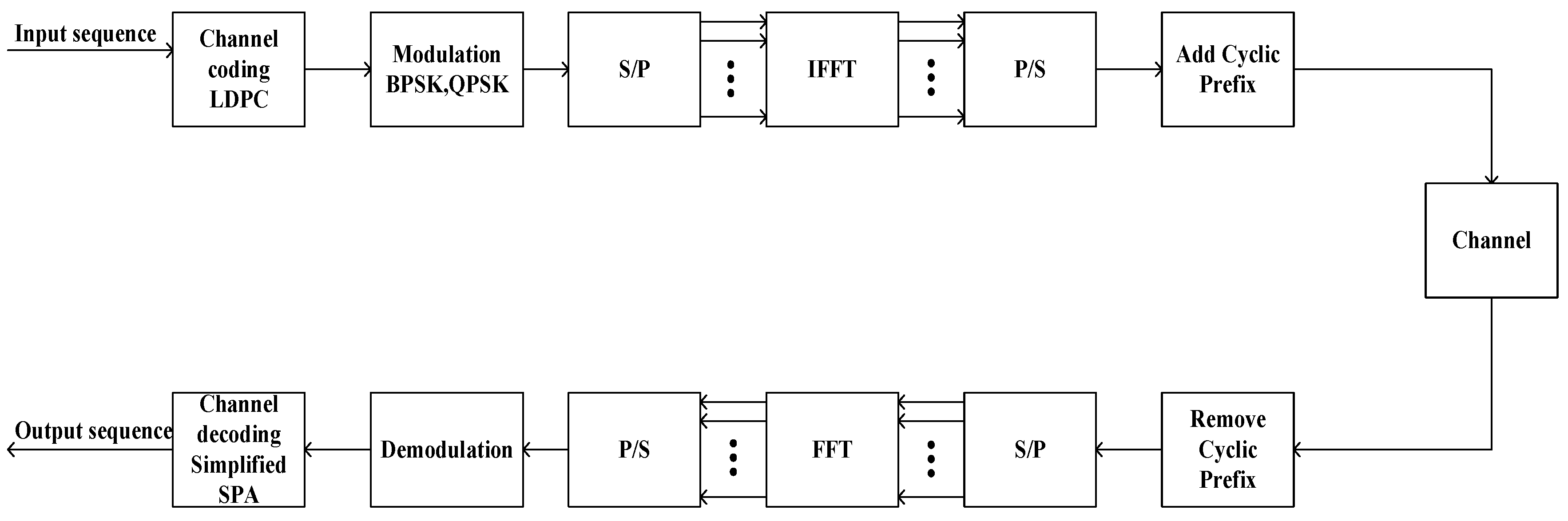
Figure 1. The binary input data sequence is LDPC encoded, then modulated using BPSK or QPSK techniques, converted from series to parallel by the S/P block, applied to an Inverse Fast Fourier Transform (IFFT) block, then converted back to series by the P/S block; finally, the cyclic prefix is added and the resulting signal is transmitted through the channel. At the receiver the inverse operations are performed: the cyclic prefix is removed, the data is converted from series to parallel by the S/P block and applied to a Fast Fourier Transform (FFT) block, then converted back to series by the P/S block, demodulated and LDPC decoded using the sum product algorithm (SPA) algorithm.
2.1. LDPC Coding and Decoding Algorithms
This section describes the LDPC codes and presents the simplified sum-product algorithm for LDPC decoding [
48].
2.1.1. LDPC Codes
Channel coding can be defined as converting bit sequence of length k in a codeword of length n, following certain rules imposed by the channel codes. One important class of such codes is the block codes. Therefore, for a (n, k) block code, the channel encoder accepts data in successive blocks of symbols of k length, adds (n − k) redundant symbols algebraically linked to the k message symbols resulting in an encoded block with n symbols called codeword. The block codes have to be linear, in order to reduce the complexity of the encoding process, and have to have a systematic structure, meaning that there is a message part of k information symbols that remains unchanged during the encoding process and a redundant checking part of (n − k) parity-check symbols.
A useful matrix associated with linear block codes is the generator matrix, denoted by G, of (
kxn) dimensions
In order to fulfill the encoding process, it has to be multiplied with the message vector
m
to obtain the codeword
Therefore, a codeword
c is a linear combination of
k basis vectors
. A linear systematic (
nxk) block code is described by
G in the following form
where
is the unity matrix of dimension (
kxk) and
is the matrix of dimension (
kx(
n − k)) where the columns represent the positions of parity checks. Therefore, the codeword of a systematic linear block code has the following form
where
b represents the parity-check bits.
Another useful matrix is the parity-check matrix denoted by
of dimensions ((
n − k)
xn) defined as
and it can be easily seen that
which means that the parity-check matrix for a (
n,
k) linear systematic block code
has a null-space vector of k dimension with basis
.
The LDPC codes belong to the linear block codes family which can be defined by a very sparse parity-check matrix (very few 1 s in each row and column, the rest being all zero) [
48] and respect the equations mentioned above. In this paper, we considered regular LDPC codes, with a constant number of 1 s on rows and columns. After the LDPC coding, the resulting codeword is mapped using a signaling constellation M, obtaining a vector s. In this paper, BPSK with
M = {
−1, 1} and QPSK with
M = {1 +
i, 1 −
i, −1 +
i, −1 −
i} signaling are considered.
2.1.2. Decoding
In the decoding process, the sum-product algorithm (SPA) is being taken into consideration which is a soft decision algorithm that accepts as input the probability of each bit that has been received. This algorithm is based on the factor graph representation of the sparse parity-check matrix, updating iteratively the soft data between check nodes
m and variable nodes
n [
49].
The iterative process for SPA, used for LDPC codes, is summarized as follows [
50]:
- Step 1.
Initialization: variable nodes are initialized;
- Step 2.
Update check nodes: a check node m gathers all incoming messages and evaluates the message sent to the variable node n;
- Step 3.
Update variable nodes: a variable node passes the message to all the check nodes in connection with it;
- Step 4.
Decision: all messages of a variable node n that indicates the probability to decode the variable node n to 1 or 0 can be obtained by adding all incoming messages to the variable node n. After each iteration, a soft decision on variable n is taken—decoded as zero or decoded as one. If a valid codeword can be formed, the algorithm stops and the decoding result is out. If not, the algorithm returns to Step 2.
The SPA needs high computational complexity because of the numerous multiplication and division operations made to complete check node updates. Therefore, a simplified version of SPA is being proposed that replaces those operations with additions and subtractions.
In this paper, we take into consideration the simplified SPA algorithm to decode the received data.
2.2. OFDM
Instead of transmitting a high-rate data stream using a single subcarrier, the OFDM technique can be used, which transmits a large number of closely spaced orthogonal subcarriers transmitted in parallel, each subcarrier having a low rate.
Figure 1 illustrates the operations made upon a signal to obtain the OFDM symbol.
The input bits are coded and mapped, according to the techniques presented above, to data symbols that are complex numbers representing the modulation constellation points. A serial-to-parallel converter is applied, associating a subcarrier to each OFDM symbol. The next step is to use an Inverse Fast Fourier Transform (IFFT) algorithm on the parallel complex data, that transforms the data into the time domain from the frequency domain. The IFFT block receives
L data symbols,
L representing the number of subcarriers and the output is
L orthogonal sinusoids that form a single OFDM symbol. After a parallel-to-serial conversion, meant to extend the transmission time for
L subcarriers from
Ts to
TOFDM = LTs, where
Ts represents the period of the symbol, the OFDM complex signal in base band has the following form in the time domain
where
and
where
represents the carrier frequency and
represents the subcarrier spacing, and the shortest duration that accomplishes this requirement is
To avoid possible occurrence of inter-symbol interference (ISI) between two consecutive OFDM symbols, a guard interval known as cyclic prefix, appended at the beginning of each symbol, is introduced. In order to create the guard interval, either the final part of an OFDM symbol is resumed at the beginning of it, or it is filled with a null signal. In this way, the length of the signal is extended with , meaning , maintaining the orthogonality of the subcarriers.
The next step is to transmit the OFDM signal
on a carrier frequency
. Therefore, the output of the OFDM transmitter block is
After the signal passes through the channel, the OFDM receiver performs the reverse operations performed by the transmitter. Thus, the guard interval is removed, then a serial-to-parallel conversion is performed and the Fast Fourier Transform (FFT) algorithm is used to return to the original spectrum of the transmitted signal, bringing it again from time domain to frequency domain. By applying the parallel-series conversion, the reconstructed data sequence is obtained.
2.3. Multiple Access
The purpose of the multiple access is to increase the number of users that are active at a certain moment, as long as an acceptable level of signal-to-noise and interference ratio (SINR) is maintained. One main concern is the multiuser interference that can appear at the receiver end due to other users interfering with the demodulated one. In order to reduce this phenomenon, the signals transmitted by different users have to be perfectly orthogonal or have low cross-correlation values. There are numerous multiple access techniques that respect or approximate this scenario [
51], the performances being measured by means of cross-correlation level, code length and implicit system rate, efficiency of spectrum spreading, sensibility to synchronization issues, and implementation complexity.
The Walsh codes are a set of perfectly orthogonal or zero-correlated codes that can be easily generated at high rates, making them a good candidate in a communication network with a continuously increasing number of users. One main disadvantage is that the Walsh codes are limited by number, so the number of users that can access the system is fixed. Another limitation of the Walsh codes comes from the fact that these codes are periodical signals, which, in frequency domain, leads to spectral lines around which the data are gathered. The spectral spreading is nonuniform, and, furthermore, depends on the chosen code. By contrast, PN codes are not perfectly orthogonal codes, with low partial-correlation between delayed versions of them, when the delay is properly chosen, and also low intercorrelation with other different codes from the same family. The PN codes are used also because they have good spreading properties, the data being spread uniformly within the channel bandwidth, independent of the chosen code.
With both Walsh and PN, the multiple access system has better performances in terms of number of users and cross-correlation properties as the sequences are longer but this leads to a very high rate on the transmission channel and difficulties regarding demodulation due to the increased computational effort [
52]. For users that already have a high rate, the channel distortion and fading phenomenon are becoming more severe and additional techniques, like equalization, must be implemented at the receiver, leading to increased complexity and higher costs. Moreover, a long length of the spreading codes may lead to low transmission efficiency and a high transmission delay, thus a potentially long delay at the receiver and high-power consumption [
52].
Having as a starting point CDMA, numerous other multiple access techniques have been developed to solve these drawbacks. One of them is MUSA, which uses short complex-valued spreading codes and which, due to additional degrees of freedom offered by the imaginary part, exhibits lower cross-correlation properties than PN and can support a much higher number of users that share the same resource block, basically realizing a superposition process [
34]. It facilitates robust SIC implementation and can be nonbinary, compared with traditional CDMA [
38].
Binary codes are one type of complex spreading code that can be generated using {1,−1}, for both real and imaginary parts. Therefore, each element of the complex spreading code is found in this set {1 + i, 1 − i, −1 + i, −1 − i}, meaning there are four values used to form a spreading code.
Denoting
L as the length of the spreading code, 4
L codes can be formed. For example, for a length of 4, there will result 44 or 256 codes, that are not enough for networks in which the number of users is very high [
48]. Therefore, there is a need to expand the set from {−1, 1} to {−1, 0, 1} and each element of the complex spreading code is found in this set {−1, −1 −
i, −1 +
i, −
i, 0,
i, 1, 1 −
i, 1 +
i}. This means there are nine values used to form a spreading code, in total being 9
L and more suitable for networks nowadays. In case of a very high number of users, instead of {−1, 0, 1}, {−2, −1, 0, 1, 2} can be used and each element of the complex spreading code is found in this set {−2, −2
i, −2 − 2
i, −2 + 2
i, −2 −
i, −2 +
i, −1 − 2
i, −1 + 2
i, −1 − i, −1 + i, −1, −
i, 0,
i, 1, 1 −
i, 1 +
i, 2, 1 − 2
i, 1 −
i, 2 −
i, 2 +
i, 2
i, 2 − 2
i, 2 + 2
i}. Therefore, 25 values are obtained that can be used to form a spreading code, in total being 25
L. In this paper, we proposed new sets of complex spreading codes formed from the set {−1, −1 −
i, −1 +
i, −
i, 0,
i, 1, 1 −
i, 1 +
i}. For a length of 4, we obtained groups of 3 orthogonal codes and at least 16 low-correlated spreading codes, presented in Equations (13) and (14). If we increase the length of the spreading code to 8, we obtained groups of 7 orthogonal codes given in Equation (15) and at least 32 low-correlated spreading codes given in Equation (16)
and
and
The steps followed to obtain the complex spreading codes that formed the matrices presented above are:
- Step 1.
Establish the length of the spreading code depending on the number of users;
- Step 2.
Define the set of values used to obtain the spreading codes starting from {−1, 0, 1};
- Step 3.
Build the matrix that includes all the codes by individually building each vector containing one code with the length established above (for in for a number of times equal to the length of a spreading code);
- Step 4.
Calculate the intercorrelation between codes;
- Step 5.
Find the zero values of the intercorrelation in the matrix obtained above, retrieving the row and column;
- Step 6.
Create a matrix that includes all the codes with zero intercorrelation;
- Step 7.
Complete the matrix, obtained at Step 6, with codes with low correlation, in ascending order of their intercorrelation values;
- Step 8.
Assign the complex codes to the users—first the zero intercorrelation ones and then the ones with low intercorrelation.
Another idea might be to build complex spreading codes starting from PN codes (cPN) whose correlation is very low, lower than the ones obtained from MUSA codes. In this case, the algorithm is simple since all codes have the same intercorrelation values, therefore it is not necessary to sort the codes.
The steps followed to obtain the cPN are:
- Step 1.
Establish the degree of the polynomial depending on the number of users;
- Step 2.
Calculate the length of the polynomial based on its degree;
- Step 3.
Choose the generating polynomial;
- Step 4.
Define a matrix containing all possible initial states of the shift register that generates the PN codes;
- Step 5.
Build the set of complex PN codes that has the real and imaginary parts of two PN codes generated with the same polynomial but different initial conditions from which the users can choose randomly;
- Step 6.
Verify the intercorrelations between the codes from the set of codes;
- Step 7.
Assign the complex codes to the users.
2.4. Relay Transmission
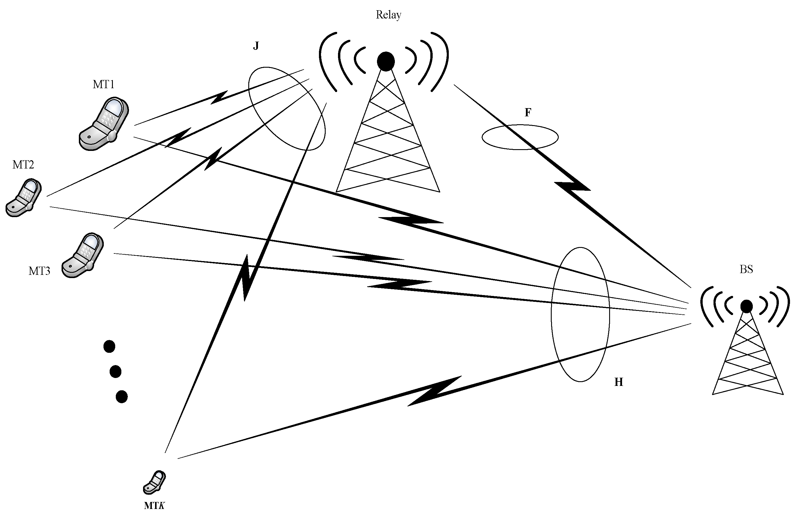
In
Figure 2 is represented the proposed architecture of the system. The relay is considered to be ideal since it can communicate with all active users simultaneously and yet treat them separately as there is only one user active at each time instant, in the attempt to minimize possible interferences between active users. This assumption has been made in order to analyze the performance achieved by the base station when the information reaches it through different paths—a direct path and an indirect path, via relay. The noise present on the channel is modeled as additive white Gaussian noise.
The spread signal is sent through the two paths mentioned above to reach the base station [
53,
54], thus the signal received by relay from the source
and the signal received at the destination from the source is
where
P denotes the power of the signal that is being transmitted;
represents the channel matrix of the
kth mobile terminal (MT), from the MT to relay;
represents the spread MUSA signal sent by the
kth MT;
represents the Gaussian noise vector of the
kth MT, from the MT to relay with zero mean and variance
;
represents the channel matrix of the
kth MT, from MT to BS;
represents the Gaussian noise vector of the
kth MT, from the MT to BS with zero mean and variance
.
If the DF protocol is taken into consideration, the signal that reaches the BS coming from the relay is described as
and is chosen that
where
Pr denotes the power of the signal that is being transmitted from the relay to BS and
if the relay correctly decoded the signal from MT;
represents the channel matrix of the
kth MT, from relay to BS;
represents the Gaussian noise vector of the
kth MT, from relay to BS with zero mean and variance
.
At the base station, there will be two synchronous copies of the same transmitted signal, taking into account the two paths assumed in system configuration. To recover the original data, a maximum ratio combiner is being used whose output is
The channel coefficients,
and
, are described as
and
with
.
3. Results and Discussion
The performance achieved by the proposed system is evaluated in this section. Extensive simulations have been made in MATLAB using the Monte Carlo technique to increase the degree of confidence in the results. The parameters are summarized in
Table 1. The number of transmitting antennas at the relay has been considered as
Ntr = 1.
To have a reference, first, we present the performance of an uplink massive MU-MIMO system when active users are separated by Walsh, PN spreading codes and then by complex spreading codes. Simulations with BPSK modulation have been performed too, but the obtained errors were very low and are not presented in the paper.
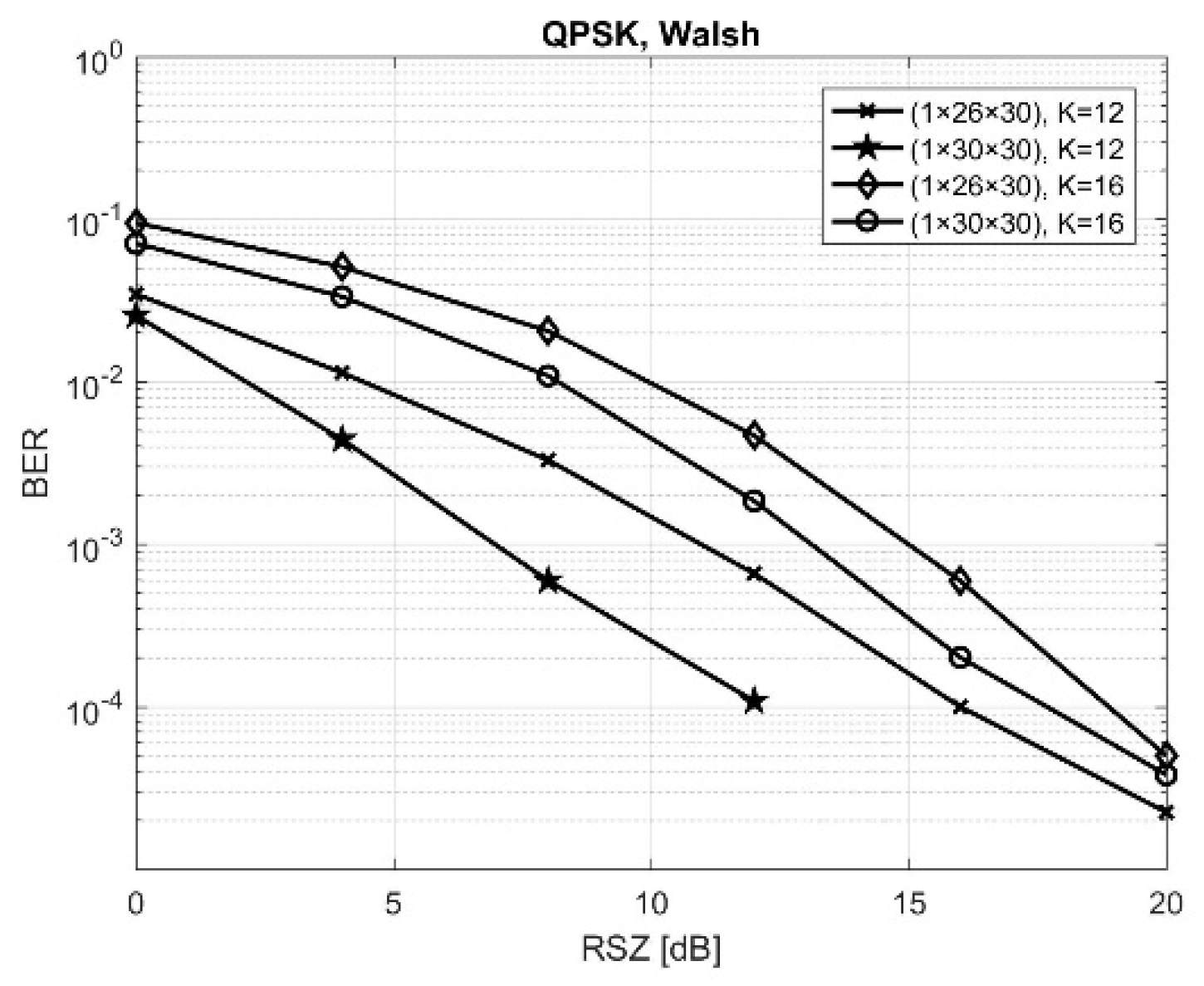
Figure 3 presents the results obtained by QPSK modulation schemes when the transmission is made over a channel affected by Rayleigh fading using a MIMO configuration of (1 × 26 × 30) and (1 × 30 × 30), with 26 or 30 antennas at the relay, where active users are separated by Walsh codes of 64-length. It can be seen that the best results were obtained when a MIMO configuration of (1 × 30 × 30) was used. It can also be noted that the performance of the system was influenced by an increase of the number of users, because the same resources were being shared so the intercorrelation noise increased. One possibility to maintain a reliable communication is to increase the number of antennas, using the spatial diversity offered by massive MIMO, as we did in our simulations when the number of receive antennas from the relay was increased from 26 to 30.
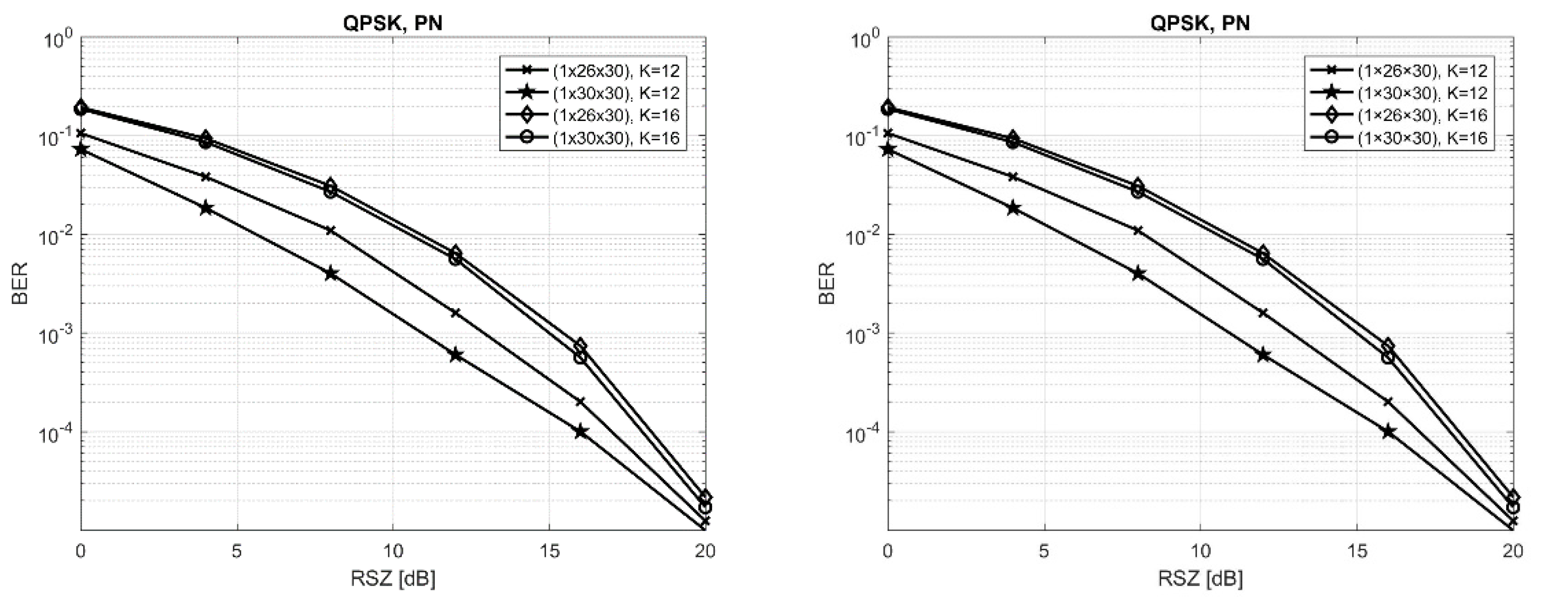
Figure 4 presents the results obtained in similar conditions, but using PN spreading codes of 63-length instead of Walsh spreading codes. It was expected that the obtained results were slightly poorer because the PN codes were not perfectly orthogonal codes like the Walsh ones, assuming a perfect synchronization at the receiver. However, PN codes are not so sensitive regarding timing synchronization and they can provide a better spectral spreading. The choice, therefore, represents a compromise between the obtained bit error rate, the spectral behavior of the overall signal, and the complexity of the receiver.
Table 2 summarizes the results obtained in the aforementioned simulations, for a fixed value of the SNR equal to 12 dB when the number of active users was 12 and 16, highlighting that the most favorable combination in order to obtain the best performance for our proposed architecture was the one that was using 30 antennas at the relay.
From those results, it can be observed that PN provides poorer results compared to Walsh.
In the above simulations, the length of the Walsh spreading codes was 64 and the length of the PN spreading codes was 63. The question that might rise might be: What should be the minimum length of the complex spreading codes necessary to achieve similar performances, taking into consideration the degrees of freedom offered by the complex part of these codes?
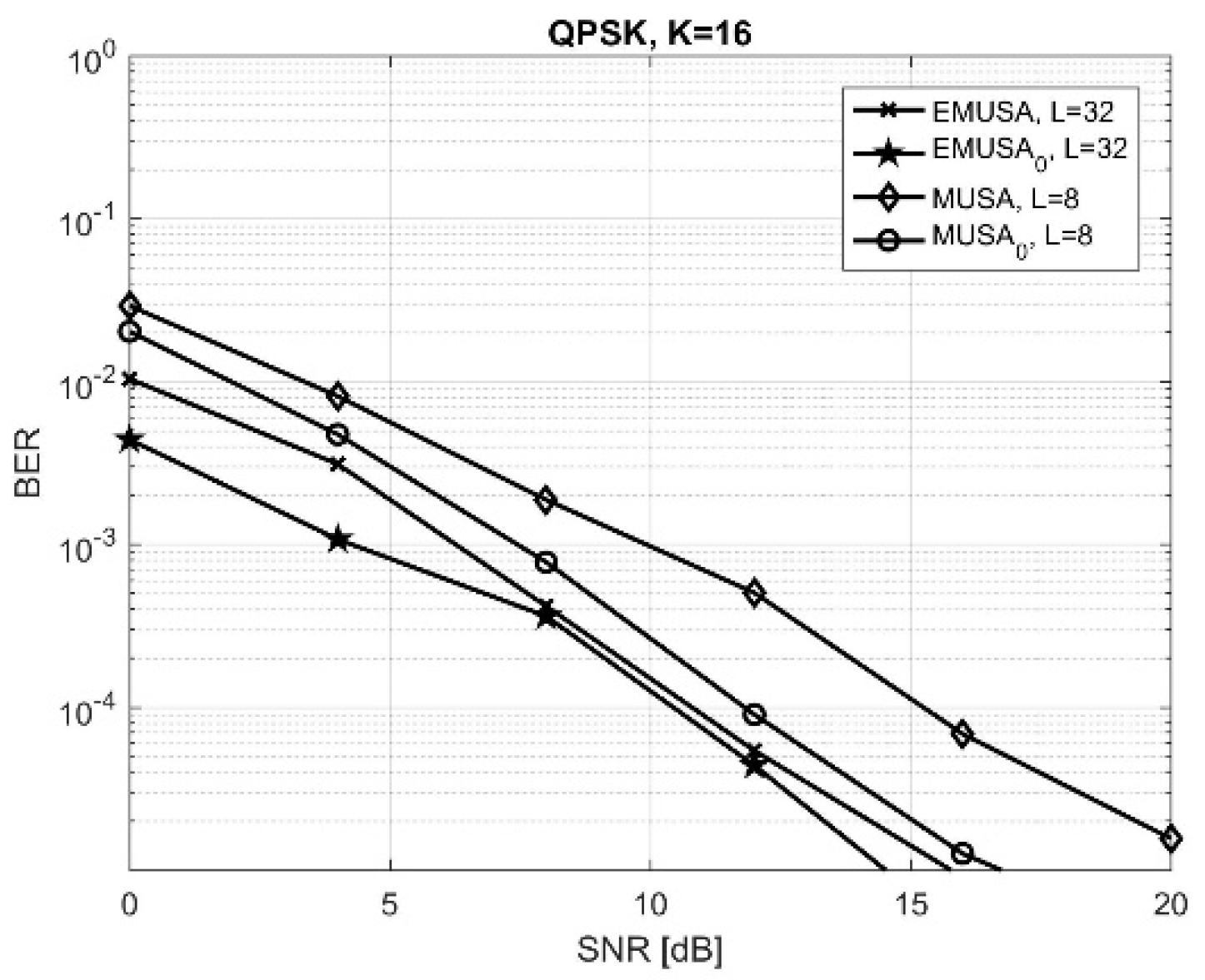
Therefore, in the following simulations, we selected four sets of codes of length 8. For the MUSA set, 32 codes with low correlation properties have been selected, matrix given in Equation (16). For the MUSA
0 set, 25 codes with low correlation properties, in ascending order of their intercorrelation value, selected from the MUSA set previously defined, and the rest of the 7 codes have been replaced with ones with zero cross-correlation, also from the matrix given in Equation (16). Then, the extended MUSA (EMUSA) set of codes was created by extending the MUSA and MUSA
0 from length 8 to length 32, obtaining thus EMUSA and EMUSA
0 sets. The results in terms of BER versus SNR in the same configuration as the one previously used and with (1 × 30 × 30) antennas are shown in
Figure 5.
It can be observed that the EMUSA sets obtained, as expected, lower BER than the MUSA sets on the same SNR, the improvement being more significant as the SNR increased, allowing a reduction of number of antennas at the relay or/and base station, but, on the other hand, the system rate increased 4 times, leading to higher spectral occupancy and higher complexity of the receiver. Therefore, depending on the application, a compromise between the processing complexity and the required level of performance has to be made.
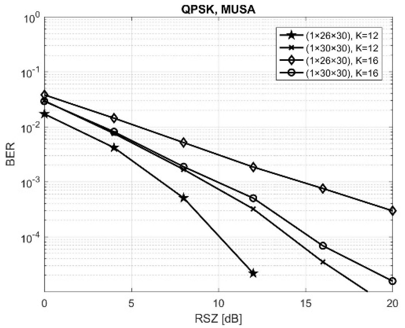
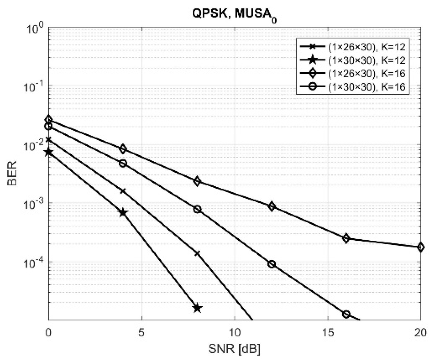
Figure 6 and
Figure 7 present the BER performances obtained by MUSA and MUSA
0, respectively, in similar conditions used for
Figure 4 and
Figure 5, with
K = 12 and 16 active users.
We can easily observe that the new combination of codes reduced significantly the BER performances, the improvement being even more important as SNR increased. This makes, thus, the MUSA and MUSA
0 sets good candidates for high-rate users in 5G NOMA-based multiple access systems.
Table 3 summarizes the results obtained by two above-mentioned situations, giving the exact BER values at SNR= 12 dB. By comparing these results with the ones presented in
Table 2, we can observe also the improvement.
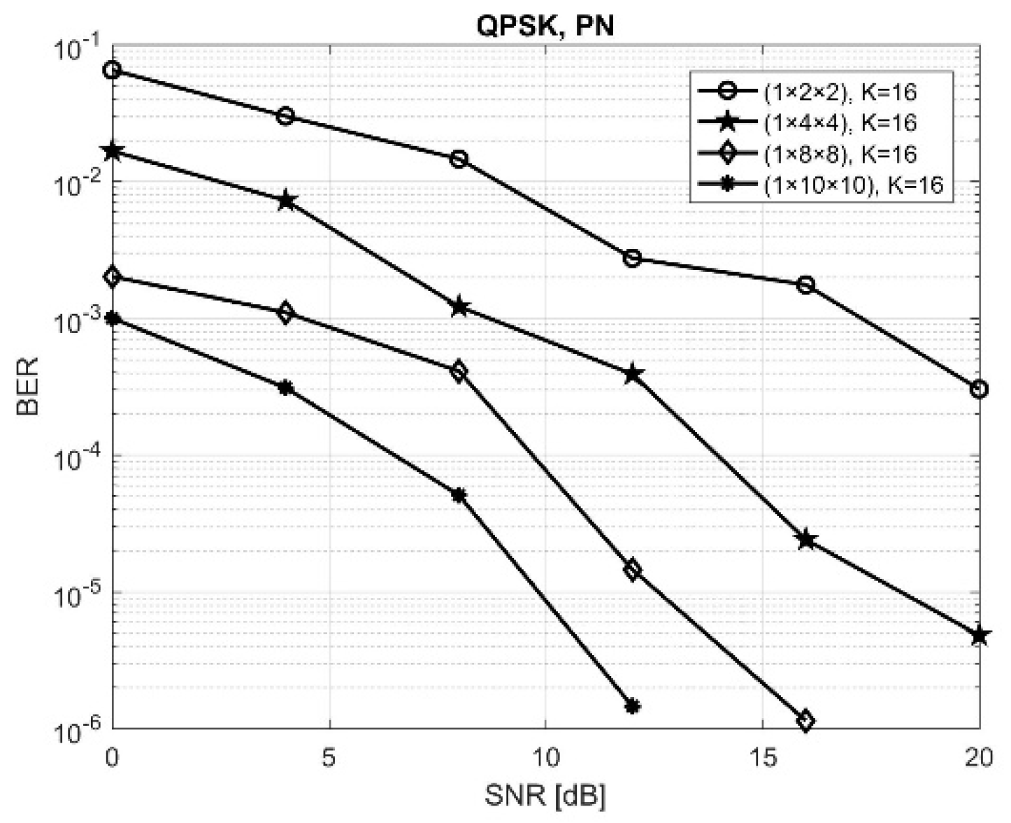
If the complex spreading codes are obtained starting from PN real spreading codes taking into consideration the
generating polynomial, where
g is the delay element, following the principles stated in
Section 2.3,
Figure 8 is obtained. It was considered the most unfavorable situation obtained in the situations above, namely (1 × 26 × 30), when the number of active users was equal to 16. Also, simulations were made in (1 × 10 × 26) and (1 × 10 × 30) configurations, but the BER performance was very low. Thus, a question has arisen: Maintaining the length of the code at 63, how much can we reduce the number of the antennas at the receiver, and therefore the system hardware complexity, such that the performances should be still acceptable (the BER should be below a given threshold)? Thus, the number of antennas at the relay and at the BS was decreased to 10, 8, 4, and then 2. Setting a threshold of 10
−4 for the BER, in (1 × 10 × 10) situation, it was reached at SNR = 8 dB, at SNR = 10 dB in the (1 × 8 × 8), and at SNR = 13 dB in the (1 × 4 × 4) situation. This shows that, using these complex PN codes, the number of antennas can be reduced significantly and, therefore, the associated costs.
In order to compare the efficiency of the present approach, we tried to compare our results with similar ones in the existing literature. Thus, in [
39], the authors have obtained several results in somewhat similar conditions to our approach but using an MMSE-SIC detector at the receiver and with different numbers of antennas at the receiver and transmitter, an approximate value for BER of 5 × 10
−2 was obtained for SNR, for 12 dB, while with our setup, we obtained BER less than 10
−3 in all configurations. In [
40], the authors obtained an approximate value for BER of 10
−4 at a SNR of 12 dB, so in this case, the results were slightly better than MUSA but lower than MUSA
0.
In [
43], a similar setup has been used, with ½ LDPC codes and QPSK/OFDM modulation, but the codes were the ones used in the 3GPP standard. The number of antennas was (1 × 2), and there was no relay between source and destination, and the channel was affected by AWGN only, obtaining a BER of approximately 5 × 10
−2 at SNR = 15 dB for MUSA, 12 users, and of about 5 × 10
−3 for overloaded SDMA-OFDMA-MLD.
4. Conclusions
The paper presents the performance obtained by an uplink massive MIMO system with relay as intermediary between source and destination, using LDPC channel coding and OFDM modulation when active users are separated using complex spreading codes from four new sets of codes, MUSA, MUSA0, EMUSA, and EMUSA0. For the MUSA set, 32 codes with low correlation properties have been selected as the intercorrelation should be as low as possible. For the MUSA0 set, 25 codes, in ascending order of their intercorrelation value, have been chosen from the MUSA set previously defined, and the rest of the 7 codes have been replaced with ones with zero cross-correlation. The extended MUSA (EMUSA) set of codes was created by extending the MUSA and MUSA0 from length 8 to length 32, obtaining thus EMUSA and EMUSA0 sets. The results were obtained using the QPSK modulation scheme, when the transmission was made over a channel affected by Rayleigh fading using a MIMO configuration of (1 × 26 × 30) and (1 × 30 × 30), with 26 or 30 antennas at the relay.
The performance was highlighted by comparing them with classical Walsh and PN spreading codes, and the new sets of codes proved to outperform the classical ones. This paper also analyzed the situation in which the number of receive antennas at the relay was different from the number of receive antennas at the destination, and some discussion was made with respect to the compromise that has to be reached between the processing complexity, total rate, and occupied bandwidth and the required level of performances in terms of BER obtained at certain SNRs.
Another novel idea, that was described and tested within this paper, was the one in which complex spreading codes cPN were obtained starting from PN spreading codes. The results obtained are promising, leading to very low BER values, showing that in this case, the number of antennas can be reduced and, thus, the overall system cost.
As future work, we will focus our attention on implementing a higher number of parallel relays between source and destination and comparing their performance when using DF or amplify-and-forward (AF) protocols and trying to find a compromise between performance, hardware, and a low cost of implementation.


