1. Introduction
The world is gradually undergoing the age of communications, facing an enormous density of traffic and connections, where everyone is online, people and objects, interacting with each other, through a multitude of applications [
1]. The modern generation of mobile communications (5G) is launched, which brings new challenges and opportunities, and will allow the creation and integration of new networks such as the internet of things (IoT) and vehicular networks, in an increasing global coverage. These systems impose a set of new requirements such as high speed data transfer, low latency, high network capacity and high connections density [
2], which involve the operation in a frequency range little used so far, in the zone of millimetre waves.
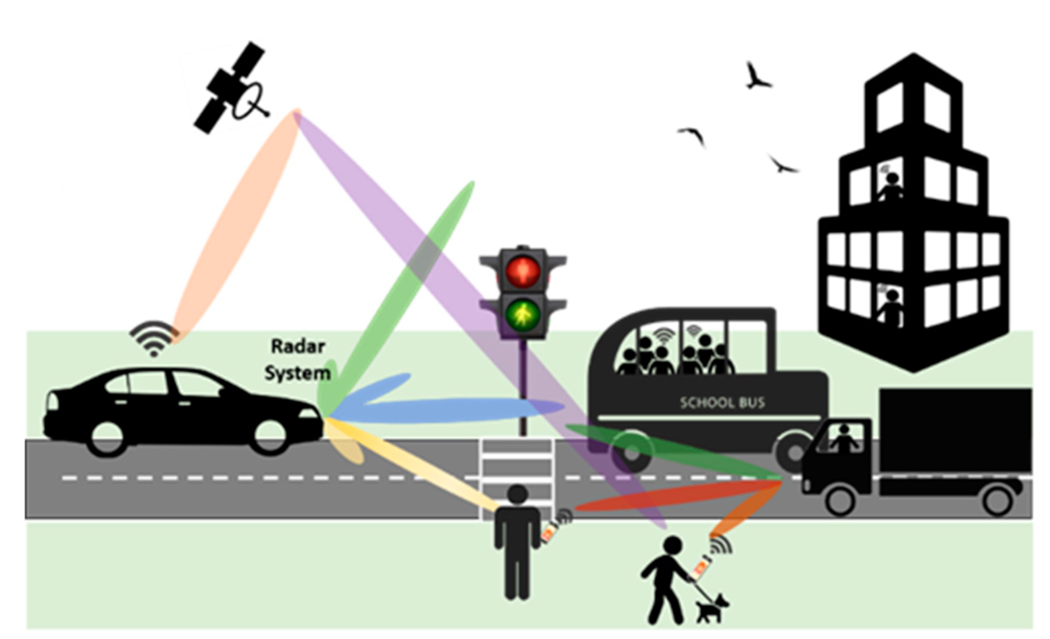
Radio detection and ranging (RADAR) technology, that was mainly used for military purposes, recently has suffered increasing attention, and its application is nowadays widespread in sports, biomedical, military or in transportation systems. Radars are used for surveillance, navigation, localization, traffic control or for weapons guidance. Currently, with the evolution of vehicular networks, smart cities and other intelligent systems, more advanced radar technologies are being developed. In the near future, the extension of the radar concept is expected for two purposes, reflectometry and communications. The scenario of
Figure 1 is foreseeable, a panoply of interconnected systems sharing information, and experiencing a huge communications density, with high risk of interferences.
Radar technology is required to filter the environment, focusing more accurately on the target or targets, as well as to mitigate interference signals from the surrounding environment. Multibeam capabilities, beamforming, high gain and tremendous versatility and reconfigurability are important aspects for modern radar systems. Additionally, most of these characteristics allow us to overcome propagation issues raised when these systems operate at higher frequencies. Thus, versatile and dynamic communication systems are needed, with the ability to continuously adjust to the applications in which they are inserted, maximizing the quality of communication. With additional signal processing capability, adaptive antennas use new digital architectures that, in real-time, dynamically adjust the radiation pattern of the array. These systems have perception of the received signal and optimize their radiation diagrams by changing the beam shape and beam direction, suppressing interferences by introducing nulls in the directions of the interference signals, changing the level of side lobes, compensating for hardware impairments and finally, accommodating the mutual coupling effects that can change the amplitude and phase of the transmitted signals. Particularly regarding automotive radars, the authors of [
3,
4] present a good example of the importance of using digital beamforming in multiantenna systems to reduce the power received in the directions of interference signals, placing nulls in the radiation pattern.
There have been technological advances in this field, where low-cost mm-wave radars composed of several antenna elements integrated in single board and with high resolution, have been presented. In [
5] is presented an example of a low-cost digital beam steering receiver (Rx) phased array for IoT device connectivity, a cheap application to get over the communication problems. In [
6], a frequency modulated continuous wave (FMCW) radar is described. This system generates multiple digital beams with high gain, low side lobe level, narrow beam width and high angular resolution control. The principles of the digital beamforming applied to synthetic aperture radar (SAR) systems are shown in [
7], as well as the improvement in the resolution achieved regarding conventional radars.
In [
8,
9], a wide variety of future applications are shown, as well as the progress that technology is facing in reducing the cost of phased array antennas. Massive antenna arrays using up to 128 elements, increasing performance and gain of radar communication systems are presented in [
10], taking advantage of digital beamforming based on coded aperture radar (CAR) technique at 77 GHz.
In [
11,
12,
13], the importance of the beamforming spectral efficiency is demonstrated, with the cancelation of undesired interferences by placing nulls in their directions that can lead to a lower bit error rate (BER).
In [
14], there is a software-defined phased array radio operating at 28 GHz that uses software to control multiple beam characteristics. However, additional hardware was required, a field programmable gate array (FPGA) board for digital control and an Ettus B200 mini software-defined radio (SDR) for data waveform control. In [
15], a highly compact 28 GHz complementary metal–oxide–semiconductor (CMOS) integrated circuit (IC) with multiple input multiple output (MIMO) and beamforming capabilities with a single wire for baseband multiplexing is reported. However, it requires heavy digital signal processing (DSP) MIMO operations to retrieve the information. A similar concept was recently shown in [
16], proposing a digital array receiver for satellite applications, also integrating DSP algorithms, operating in a single-chip RF system on chip (SoC) solution installed on the Xilinx ZCU1275 prototyping platform; however, operating in a fixed frequency range between 27.5 and 28.35 GHz. A 64-channel massive MIMO transceiver with a fully digital beamforming (DBF) architecture is presented in [
17]. The MIMO transceiver operates in time division duplex (TDD) mode, at 28 GHz with a 500 MHz signal bandwidth. A high data rate in the communication was achieved using the beam-tracking technique and two streams of 64-QAM (Quadrature Amplitude Modulation) signals. However, one of the great difficulties of this architecture is the high cost of the hardware structure that supports the 64 channels. Due to the high power consumption of the RF frontends, additional space in the circuit is required for heat dissipation. A Ka band DBF array transmitter using a direct digital synthesizer (DDS) for millimeter-wave applications is proposed in [
18], operating at 24 GHz. This system reveals a complex calibration and has fluctuation over different scanning angles that unbalance the gain of different beam peaks in the 1 × 15 antenna array. In [
19], the implementation of an X band 4 × 4 digital phased array module is shown, which includes one custom CMOS RF SoC. This system has high side lobes due to the transmitter (Tx) calibration process that involves random errors both in the phase and magnitude.
The concept of beamforming, in the sense of the ability to control the radiation shape of an antenna array, can be performed either digitally, like the examples presented previously [
14,
15,
16,
17,
18,
19], analogically (by using the frontend analog phase shifters [
20]) or in a hybrid way [
21]. A millimeter-wave hybrid beamforming system architecture based on analog phased subarray is reported in [
22]. This work uses a 32-element antenna array with a hybrid beamforming transceiver to operate at the 28 GHz band in TDD mode, with 500 MHz bandwidth. An important aspect is the reduction in the number of intermediate frequency (IF) channels compared to [
14,
15,
16,
17,
18,
19], reducing the cost comparing to fully digital architectures. However, one issue with this architecture is the analog phase shifting, which is critical to increasing the insertion loss up to 19.5 dB, requiring the use of additional amplifiers to compensate such losses. Additionally, this architecture has a higher complex design of the control signal because of the non-linearity between the control signals (amplitude weighting control) and output phase of this vector-sum phase. Authors in [
23] explored the use of a Universal Software Radio Peripheral (USRP) X310 connected to a computer capable of calculating the direction of arrival (DoA) and generating beamforming in the sub-6 GHz frequency band for a satellite transponder structure. Nevertheless, this test bed presents considerable DoA estimation errors in a lower frequency of the operation scenario.
Millimeter-wave RF systems are evolving rapidly, to some extent supported by software-defined radios. These systems provide a straightforward way to rapidly interact with hardware, and to test their use. Therefore, the combination of digital technology and versatile architectures, with adaptive antenna processing techniques, allows for powerful systems that can be used in communications and radar approaches.
In this work, a versatile and reconfigurable 4 × 4 SDR digital beamforming phased array system operating in the Ka band at 28 GHz is proposed. This system has the capability of electronically and digitally manipulating and steering the radiation pattern of an antenna array, and adjusting it to the environment, maximizing its performance and efficiency. Besides that, this system also has the versatility to, with low complexity, change the frequency of the local oscillator (LO) and the IF to implement communication systems and radar in the millimeter waves (Ka band), enabling the rapid testing of new solutions based on software-defined radio. It has also the advantage of carrying out full-duplex communication. This architecture has the potential to be used in a great variety of future scenarios such as in 5G communications, radar applications, IoT or surveillance. It is an extension work regarding the previous papers [
24,
25] with improvement in the digital processing unit and practical measurements validation.
This paper is organized into five sections, starting with the Introduction in
Section 1, stating the objectives and providing a brief state-of-the-art on SDR beamforming systems.
Section 2 presents both digital and analog components that constitute the proposed architecture of the software-defined radio (SDR) phased array system.
Section 3 describes the beamforming processing system while in
Section 4 the experimental setup and the measurement results are presented. Finally, the last section reports the main conclusions of the work.
3. Beamforming Processing
In the previous section, the architecture of the SDR system was presented, as well as the description of each analog and digital component used. In this section, taking advantage of the absolute control over each of the four Tx/Rx channels and the processing capacity that this system has, an example demonstrating some of its potentialities is presented. In this work, some examples will be presented using two possibilities, beam shaping and beam steering, to highlight the functionality of the proposed system. Nevertheless, a multitude of techniques may still be explored in the future.
Figure 10 shows a block diagram of a beamforming system, applied to a linear array with N number of isotropic elements, in reception. In this structure, each antenna element has an adjustment, by multiplying each received signal by a weight factor,
, where
is the amplitude excitation, and α is the relative phase excitation to the previous element. By varying the weight factor of each channel, and properly estimating its values, it is possible to control the radiation pattern of the array.
The far field of the array factor can be written according to the Equation (1), which relates the contribution of each element for the total radiation of a linear array.
In Equation (1), the summation of independent phasors (weights), the progressive phase is represented by ψ = kd cosθ+α, where k = (2π⁄λ) and d the distance between elements of the array.
3.1. Beam Steerin
Considering an array of N = 4 elements, with equal and unitary excitation amplitude for all elements,
, the respective phase delay to apply to each channel in order to have the array steer its radiation to the position θ is given by
.
Table 1 shows the estimated phase delays for each channel, considering the set of chosen locations (θ), using an array of half-wavelength spaced elements.
3.2. Beam Shaping
The concept of beam shaping is vast and brings together all the techniques that, through feeding of the array, allows the modification of its radiation shape. Typically, this concept is used in communications to mitigate the influence of interfering signals through side lobes (reducing or eliminating them) or confining the width of the main lobe.
There are different reported methods in the literature, such as the Schelkunoff polynomial method, minimum mean-square error (MMSE) weight and many others, and in this work, two methods, Dolph–Tschebyscheff and binomial [
27], were applied in the proposed digital system and tested to demonstrate their impact on the radiation of the antenna array when compared to the uniform array.
Using the theoretical expressions of [
27], for the array of N = 4 elements, the feeding distributions were estimated for the binomial method and for the Dolph–Tschebyscheff technique using different values of side lobe level (SLL), such as −15 dB, −20 dB and −25 dB. The SLL represents the signals being radiated in the unwanted direction. Applying such methods in practical application could be very helpful to reduce the interferences.
These distributions are provided in
Table 2 and were applied to the theoretical Equation (1). In the Matlab, the different radiation patterns, considering all the techniques, were calculated using (1) and multiplying by the theoretical beam pattern of a microstrip patch antenna (element factor), which is the radiating element chosen. The results are shown in
Figure 11.
According to
Figure 11, it is possible to observe several aspects resulting from the use of each method. First, using the uniform distribution, with all elements fed with equal amplitude and phase, a higher side lobe is observable, and the amplitude of this lobe reduces with the application of the different methods, namely using the Dolph–Tschebyscheff technique (for the different SLL estimations), and in particular using the binomial method, for which the side lobes even disappear. It can also be proved that the amplitude distribution from the application of the Dolph–Tschebyscheff method for very small SLL values will tend towards the binomial distribution.
Another important aspect that can be taken from
Figure 11 is the variation of the half power beam width (HPBW), using the different methods, observing that this value increases as the value of the SLL decreases.
The standard definition of beam width is the angle aperture from which most of the power is radiated from antennas [
27]. It is a very important characteristic of an antenna array, and a crucial characteristic in phased array antennas and beamforming, because of the useful advantage of minimizing unwanted interference signals by controlling the main lobe characteristics, beam width and the side lobes.
The concept of half power beam width (HPBW) is commonly used and reflects the angular aperture in which the gain of the antenna falls 3 dB. There are theoretical expressions reported in the literature [
27] that estimate this value.
4. Measurement Setup and Results
The measurements scenario of the proposed system is illustrated in
Figure 12. The setup was placed in an anechoic chamber, and included a power supply, providing the DC voltage to the RF up/downconverter’s boards and the PLL LMX2595 (LO frequency of 12.08 GHz). In addition to the frontend boards and the PLL, the setup also included the Host-PC, the Tx and Rx antenna arrays, and the USRP N310, as can be identified in the
Figure 12.
Before starting the measurement process, and after carefully placing all the elements of the setup, the first task was to calibrate the system, in order to ensure that all signals reached the antennas in phase, and all signals received maintained their properties until they were read by the USRP. The principle of calibration is the same as beamforming, and consists of adding certain weight (phase and amplitude) to each channel with the purpose of compensating for the hardware impairments in the upconverter/downconverter modules, the phase differences in the USRP daughterboard and the temperature drifts. Using the Python/Matlab interface, a calibration routine was developed to compensate for the phase and amplitude differences of the channels.
The four elements of the transmitter phased array antenna were placed in the rotor arm of the anechoic chamber, 65 cm away from the receiver (ensuring the far field distance). In Matlab/Python, a function that calculates the correct phase to apply to each channel based on the desired direction of beamforming was developed. The USRP modulated the baseband signal into two orthogonal carrier waves, thus generating a 3.84 GHz IF signal. This signal was then applied to an upconverter module that converted it to 28 GHz. The resultant signal was fed into one element of the antenna array. Since there is a channel digitally controlled (in amplitude and phase) for each element of the array, it is possible to use various beamforming algorithms. In the tests carried out, the radiation beam varied (in relation to the perpendicular plane of the array) between −40° and +40° with one degree increments. This procedure was repeated for nine different positions of the transmitter. For each step, the received signal in the antennas were captured, downconverted to 3.84 GHz, and then the IQ demodulation was performed in the USRP to obtain the IQ samples. From these received samples, it was possible to measure the amplitude and phase of the signal coming from each channel.
The first measurement using the system was related to beam steering, in which the phases estimated in
Table 1 were applied to the four channels, to steer the beam to different angles.
Figure 13a shows the normalized measured radiation patterns of the received signal for nine different positions of the transmitter, using uniform amplitude in the feeding of the array.
The second measurement was devoted to the beam width of the radiation pattern. It is possible to observe good agreement between the estimated curves of the array factor (
Figure 11) and the measured values of the radiation pattern of
Figure 13b. It is noticeable that the radiation pattern with the widest beam is the one that uses the binomial distribution (27°) and the narrowest beam is related with those that use uniform distribution (17°).
Table 3 compares the information of the measured beam widths of radiation patterns from
Figure 13b and those taken from the theoretical results of
Figure 11. It is possible to verify good correspondence between the evolution of these values.


