Article

Improving a Cable Robot Recovery Strategy by Actuator Dynamics

Department of Management and Engineering, University of Padova, 36100 Vicenza, Italy
*
Author to whom correspondence should be addressed.
Appl. Sci. 2020, 10(20), 7362; https://doi.org/10.3390/app10207362
Submission received: 29 August 2020 / Revised: 10 October 2020 / Accepted: 15 October 2020 / Published: 21 October 2020
(This article belongs to the Special Issue Advances in Mechanical Systems Dynamics 2020)

Abstract

:
Cable-driven parallel robots offer several benefits in terms of workspace size and design cost with respect to rigid-link manipulators. However, implementing an emergency procedure for these manipulators is not trivial, since stopping the actuators abruptly does not imply that the end-effector rests at a stable position. This paper improves a previous recovery strategy by introducing the physics of the actuators, i.e., torque limits, inertia, and friction. Such features deeply affect the reachable acceleration during the recovery trajectory. The strategy has been applied to a simulated point-mass suspended cable robot with three translational degrees of freedom to prove its effectiveness and feasibility. The acceleration limits during the recovery phase were compared with the ones obtained with the previous method, thus confirming the necessity of contemplating the properties of the actuators. The proposed strategy can be implemented in a real-time environment, which makes it suitable for immediate application to an industrial environment.

1. Introduction

Cable-driven robots, commonly called cable robots, are an important field in robotics. The parallel structure of cable robots leads to high payload capacity and high speeds of the end-effector throughout their workspace [1] due to low-moving masses. Moreover, cable robots stand out from other parallel robots since their links are constituted by cables wounded around actuated pulleys, allowing not only for a simple and cheap design but also for large workspace manipulation tasks. These advantages lead to a wide spreading of cable robots, which not only have been suggested for industrial applications [2] but also for home assistance and rehabilitation purposes [3] and for entertainment [4].
With respect to rigid-link parallel robots, the use of cables introduces an additional constraint due to their ability to resist tension but not compression, thus each wire can pull but not push the end-effector. This leads to safety concerns when cable robots are adopted in crowded areas or interact with humans, especially since an emergency stop procedure for these devices is not as simple to implement as in rigid-link robots. Although the damage occurring due to failures of cable-driven manipulators can be very severe, research on failure analysis and fault tolerance has not been sufficiently explored [5] in comparison to serial manipulators. Indeed, implementing an emergency procedure for these manipulators is not trivial, since stopping the actuators abruptly does not imply that the end-effector rests at a stable position, thus making failure analysis particularly challenging for cable robots.
An analysis of failure modes was provided in [6] as an application of the proposed wrench-based analysis, which can determine if a failure is due to a negative tension, i.e., compression, or if the tension limits of a wire have been exceeded. In [7], the faults due to wire jamming, i.e., wire at a constant length, are also presented and the author proposed a certain degree of redundancy to provide fail-safe operation and fault tolerance.
A very basic solution to improve safety in case of cable failure at the design stage can be admittedly achieved by increasing the number of cables far beyond the minimum needed: indeed, cable robots with many degrees of redundancy present a higher fault tolerance, particularly with a broken cable. However, this approach is far from being the optimal one, since, in addition to being more expensive, cables tend to obstruct the workspace and it can even be difficult to avoid interference between the cables. Therefore, it is important to safely control the robot in case of failure without increasing cable redundancy excessively. In [8], an emergency strategy for a two-dimensional cable robot is presented. This strategy aims to guide and stop the end-effector in a safe position on the basis of two different approaches: minimization of the kinetic energy and potential fields. In [9], a recovery strategy for a spatial 3-DOF four-wires cable robot is presented: the proposed approach aims at safely recovering the end-effector after a cable failure by controlling the robot with an elliptic trajectory even outside its residual Static Equilibrium Workspace (SEW) (i.e., a set of the end-effector poses, for a given motor mount configuration, where static equilibrium can be obtained while applying tension to all cables, assuming infinite maximum cable lengths and tensions [10]).
Indeed, cable failure induces a variation in the SEW which should be taken into account by the recovery strategy algorithm. This is shown in [11], where a feasible motion leads the end-effector toward a Safe Pose (SP), where static equilibrium can be achieved. The end-effector is then stopped at the SP. The approach splits the recovery trajectory into two parts, each with different motion requirements, called the Connecting Path and Straight-Line Path, respectively. The first one is needed to change the direction of motion of the end-effector since it is not guaranteed that it is moving towards the SP; the latter is a linear trajectory path used to reach and stop the end-effector at the SP. Furthermore, the authors exploited the Wrench Exertion Capability (WEC) [12] index which belongs to the family of performance indexes that take into account the direction of motion [13,14]. In this work, we considered the computation method presented in [15], which allows for computing cable tensions along the straight-line trajectory on-line. The algorithm offers great flexibility since it can be applied to any cable robot topology (i.e., under-actuated [16], fully actuated [17] or redundant cable robots [18]), in the presence of any number of broken cables, provided that a not-null static equilibrium workspace is available after cable failure. However, this approach does not take into account the physical features and the dynamic limits of the actuators, i.e., limited exertable torque, moment of inertia and presence of friction, which could affect the feasibility of the recovery strategy.
Therefore, the aim of this work is to take into account the actuator limits to improve the recovery strategy introduced in [11]. The formulation of the optimization problems is improved by adding the constraints related to the actuator dynamics. Moreover, this work provides an alternative real-time approach for each part of the recovery trajectory. These algorithms can be more suitable than time-consuming linear programming approaches, enabling the use of this strategy in real-time applications. The recovery strategy has been tested in a simulation environment to show its feasibility. Lastly, the trajectories and acceleration constraints obtained by using the new formulation and without considering the actuator dynamics are compared.
The paper is organized as follows: Section 2 introduces the cable robot model adopted and Section 3 presents the recovery strategy proposed considering the physics and dynamics of the actuators. The simulated tests and results are discussed in Section 4. Lastly, Section 5 concludes the work.

2. Cable Robot Model

The proposed strategy was applied to a 3-DOF suspended cable robot with four cables, as represented in Figure 1. This configuration is particularly challenging since suspended cable robots rely on gravity to maintain equilibrium. The end-effector was considered as a point mass with only translational DOFs, since its size can be considered negligible with respect to the magnitude of the workspace. This assumption allows for simplifying the dynamics and kinematics of the end-effector without a lack of generality; indeed, the most important goal of the after failure strategy consists in avoiding collision of the end-effector. Furthermore, the strategy can be applied only if the robot is at least fully constraint after failure, therefore we must assure a minimum number of cables to control all the DOFs. In this specific case, four cables are needed before failure. Hence, for the considered robot, we suppose that only one cable breaks at a time.

2.1. Robot Dynamics

The overall wrench w applied on the end-effector of a cable robot, meant as the forces f and torques t , is the sum of the cable forces w c and the external forces w ext , e.g., the gravitational load. By defining a n x m matrix, called the structure matrix S , as
S n x m = [ u 1 u 2 u m ]
where each column u i is the unit vector oriented from the end-effector towards the i -th pulley. A relation between the cable tensions τ and the cable forces w c can be obtained
w c = S τ
A more complete formulation [12] can be obtained by considering the external wrench w e in the structure matrix S by defining a new matrix W
w = w c + w e = S τ + w e = [ S w e ] τ T 1 T = W τ w
Therefore, it is possible to evaluate the cable tensions τ w , which are required to move the end-effector.

2.2. Actuator Dynamics

After the evaluation of τ w , it is necessary to study the actuator dynamics to evaluate the actuator torques. Each considered actuator comprises an electric motor, a drum and a rotating pulley. The dynamics of each actuator i can be described as follows
j m θ ¨ i = b θ ˙ i + c i + ρ τ i
where j m is its moment of inertia, θ i is the position of the motor, and therefore θ ˙ i and θ ¨ i are the motor velocity and acceleration, respectively. b is the friction coefficient, c i is the motor torque and ρ the drum radius. j m , b and ρ have been assumed as constant, since the mass of the cables are negligible with respect to the magnitude of the system. It is possible to gather (4) in matrix form for all the actuators as follows
j m θ ¨ = b θ ˙ + c + ρ τ
A relation between the wire length l i and θ i , and therefore θ ˙ i and θ ¨ i , can be defined as
| l i | = l i 0 + ρ θ i | l ˙ i | = ρ θ ˙ i | l ¨ i | = ρ θ ¨ i
By obtaining θ ˙ i and θ ¨ i from (6) and substituting in (5), it is possible to evaluate the motor torque as
c = j m ρ l ¨ + b ρ l ˙ ρ τ
Equation (7) defines the relation between actuator torques and the cable tensions. Moreover, the addition of other transmissions to the considered system does not change the equation form.

3. After Failure Strategy Approach

The proposed after failure strategy approach aims to drive the end-effector inside the residual SEW in a minimum time. Indeed, when a cable breaks, the robot workspace changes and the end-effector might lie outside the residual SEW. Therefore, as a cable failure occurs, the SP must be defined as the final landing position inside the residual SEW. Several factors influence the coordinate choice, such as the robot pose after failure or the presence of obstacles or dangerous zones in the robot workspace. Without lack of generality, the SP should be placed at a suitable height with respect to the workspace. Regarding the x , y coordinates, they are defined as the barycenter of the area obtained as the intersection of the horizontal plane passing through the points at the chosen height and the residual SEW.
Once the SP has been identified, the goal of the study is to plan a linear trajectory that allows one to reach it from the point where the failure occurred. However, since the end-effector velocity could not be null or directed towards the desired direction, it could be not feasible to plan a straight line path immediately after failure. Thus, it is necessary to firstly define a Connecting Path to change the direction of motion towards the SP. Once this requirement is satisfied, the linear trajectory can be planned.
The Connecting Path approach will be presented in Section 3.1, and the linear trajectory planning in Section 3.2.

3.1. Connecting Path

As stated before, the direction of motion d of the end-effector after failure should be oriented towards the SP. Thus, any velocity components orthogonal to d should be null or a suitable small value. To reach this goal, during the first part of the recovery approach a suitable force should be applied to the end-effector.

3.1.1. Linear Programming Problem

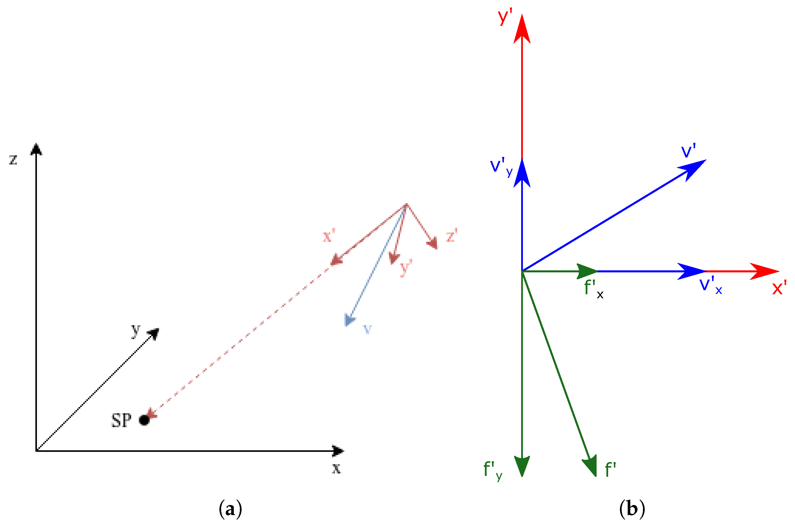
To easily identify any velocity components orthogonal to the direction d, it is suggested to introduce a mobile reference frame placed on the end-effector with the x-axis aligned with d. This frame is obtained after a sequence of three rotations
  • The first two rotations R z ( α ) and R y ( β ) are applied to align the x-axis with the direction d of the desired velocity component;
  • The third rotation R x ( γ ) is such that the undesired velocity component (i.e., the orthogonal one) is aligned with the y-axis.
The overall rotation matrix R is therefore defined as
R = R z ( α ) R y ( β ) R x ( γ )
The end-effector velocity vector v can be expressed in the mobile reference frame as:
v = R T v = v x v y v z T = v x v y 0 T
As stated in (9) and represented in Figure 2a, v z is always null, v y is always positive and v x will be positive or negative depending on the initial velocity value. The desired velocity should therefore be obtained by reducing v y to a suitable small value, while v z is kept to a null one. This can be achieved if the exerted force f is defined in the mobile reference system such as
f = f x f y f z with f x > 0 f y < 0 f z = 0
as represented in Figure 2b.
The exerted force f can be defined in terms of τ w to obtain the required value to change the velocity direction
f = R T f = R T W τ w = W R τ w = w R x T w R y T w R z T τ w
The novelty of the proposed approach consists of introducing constraints on the exertable actuator torques. It is indeed possible to evaluate the actuator speed θ ˙ i in terms of the end-effector speed v from (6) as follows
θ ˙ i = l ˙ i ρ = u i T v ρ
Analogously, the actuator acceleration θ ¨ i can be expressed as:
θ ¨ i = l ¨ i ρ = u i T r ¨ u ˙ i T v ρ
Substituting (12) and (13) in (5) the actuator dynamics can be expressed as:
c i + τ i ρ + b u i T v ρ = j m u i T r ¨ ρ j m u ˙ i T v ρ
and the torque c i of each actuator can be related to S by obtaining the acceleration of the end-effector r ¨ from its dynamics:
M r ¨ = S τ + G
where M is the mass matrix of the end-effector and G the weight of the platform, thus obtaining:
c i = b ρ u i T v j m ρ u ˙ i v τ i ρ j m m ρ u i T S τ j m m ρ u i T G
Lastly, the equations of the torques c i of the actuators can be grouped in matrix form
c = b ρ S T v j m ρ S ˙ T v + I ρ j m m ρ S T S τ j m m ρ S T G
The maximum breaking effect can be found by solving the linear programming problem defined as follows
m a x i m i z e : ( s i g n ( v y ) f y ) = ( s i g n ( v y ) w R y T τ w ) s . t . w Rx T τ w > 0 w Rz T τ w = 0 0 τ min τ τ max τ f = 0 c max + b ρ S T v + j m ρ S ˙ T v + j m m ρ S T G > I ρ j m m ρ S T S τ c min + b ρ S T v + j m ρ S ˙ T v + j m m ρ S T G < I ρ j m m ρ S T S τ
where τ f the tension referred to the broken cable, which is therefore null, τ min and τ max vectors containing the lower and upper bound of each cable tension and c min and c max the lower and upper bound of each actuator torque. The algorithm calculates a new tension configuration τ at each step to achieve a suitable deceleration until v y takes a small enough value. After this, the direction of motion d is oriented at the safe point and a straight line path can be carried out.

3.1.2. Real-Time Approach

The presented solution, based on a linear programming algorithm, is not suited for a real-time application, due to the excessive time needed for computation. However, a real-time approach provides a more flexible and less constrained solution, despite requiring more computation power than an off-line one and providing an approximate solution. To evaluate the maximum force that can be applied to the end-effector to change its velocity direction, this approach applies the WEC index geometric formulation proposed in [15]. Indeed, the WEC index, as stated in [12], is a useful tool to evaluate the maximum wrench that can be exerted along a given direction d while keeping null all the other wrench components. The adopted geometric approach is based on the definition of two n-dimensional polytopes: T , which represents the acceptable cable tension configurations, and Ω , which represents the corresponding forces exerted on the moving platform [15]. The latter can be obtained from S T and T and provides a graphical evaluation of the maximum and minimum force applicable along a given direction.
However, this approach requires the definition of the direction to analyse, which cannot be predetermined when defining the Connecting Path. Hence, this work applies the following iterative procedure to define the appropriate direction:
  • In the first iteration, the algorithm rotates the mobile reference frame of 90 along the z-axis, in order to align the x-axis with the direction opposing v y ;
  • The WEC index geometric formulation is used to evaluate the maximum and minimum force along the new x-axis;
  • The evaluated force limits are verified in terms of cable tensions and actuator torques, i.e., the constraints in (18) must be satisfied;
  • If the constraints are not satisfied, a new iteration is carried out, rotating the initial mobile frame along the z-axis of an angle lower than the previous one, i.e., <90 , until the constraints are fulfilled.
Despite its iterative nature, the proposed approach has showed to be an order of magnitude faster than the linear programming approach in several tests.

3.2. Motion Planning along a Straight Path

It is not possible to predetermine the motion planning along d, since the end-effector position and velocity when the cable breaks are not known a priori. Nonetheless, it is possible to use the WEC index to evaluate the acceleration limits [11] along the desired direction d, thus obtaining the maximum braking acceleration to stop the end-effector in the SP.

3.2.1. Wec Analysis

As stated in (3), the total wrench exerted on the mobile platform is related to the cable tensions by W . By referring to the mobile reference frame applied to the end-effector, i.e., with x-axis along d, we can define
W R = R T W = w R x T w R y T w R z T
where w R x T represents the total force applied along d, which should be maximized to reduce the braking time and, analogously, w R y T and w R z T represent the total force applied along the y and z axis, respectively.
As presented in [12], the maximum exertable force w f , d can be computed by solving the following linear programming problem
m a x i m i z e : ( w f , d = w x T τ w ) s . t . w y T τ w = 0 w z T τ w = 0 0 τ min τ τ max
Similarly to the linear programming problem described in Section 3.1, it is possible to adopt (20) for the considered problem by adding three constraints: one that represents the cable failure, i.e., imposing a null τ f , and two for the torque limits. The linear programming optimization problem is therefore
m a x i m i z e : ( w f , d = w x T τ w ) s . t . w y T τ w = 0 w z T τ w = 0 0 τ min τ τ max τ f = 0 c max + b ρ S T v + j m ρ S ˙ T v + j m m ρ S T G > I ρ j m m ρ S T S τ c min + b ρ S T v + j m ρ S ˙ T v + j m m ρ S T G < I ρ j m m ρ S T S τ
with the same nomenclature used in Section 3.1. By solving the linear programming approach, the maximum and, in a similar way, the minimum force limits along d are evaluated.
The acceleration limits of the end-effector in each point, which is a fundamental requirement for the motion planning, can be estimated as follows
a l i m = w f , d m
where m is the mass of the end-effector.

3.2.2. Real Time Approach

Since the presented WEC formulation can only evaluate the force limits, and thus the acceleration ones, in only one point in time, it is necessary to analyse all the points composing the straight line path, which are not known beforehand.
This work adopted a real-time approach to evaluate the acceleration limits since it is more flexible to changes in the SP position and robot configuration; moreover, the resulting limits are less strict, thus reducing the time needed for the recovery strategy. However, the real-time approach requires faster algorithms, thus a new strategy, based on the evaluation of the WEC presented in Section 3.1.2, has been implemented. Since the fast evaluation of the WEC does not consider the constraints on the actuator torque, the adopted procedure is the following:
  • Evaluation of the fast WEC and the acceleration limits along the direction d;
  • Given the acceleration limits, using (7) it is possible to evaluate the maximum and minimum value of the actuator torque corresponding to the acceleration limits;
  • If the torque limits are not respected, the acceleration limits are reduced to fulfill the constraints. This step is iterative and is not completed until the torque constraints are respected.
This procedure is applied for a variable number of points along d: this number is a compromise between the desired accuracy and the required computation speed.
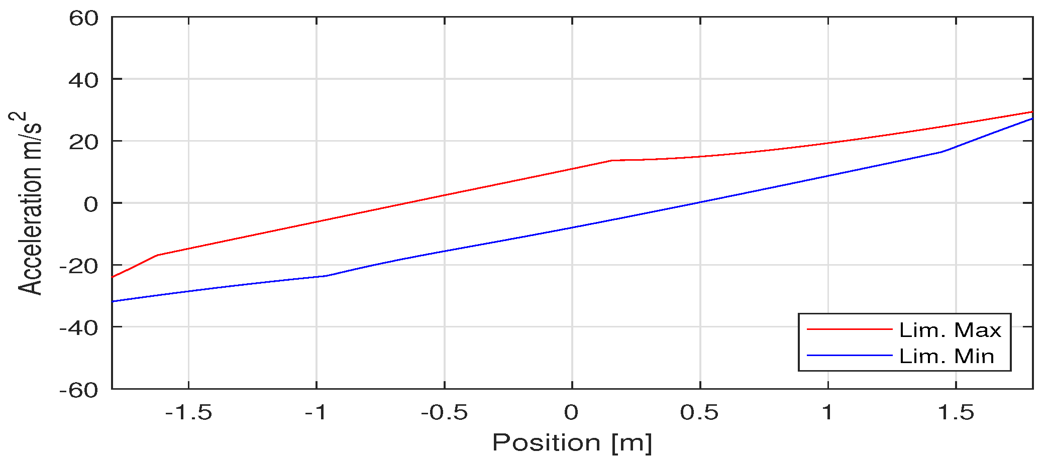
Figure 3 shows an example of the maximum and minimum acceleration values along d, in red and blue, respectively, with the x-axis representing the distance from the SP.
Negative values of the distance, i.e., points which are placed beyond the SP from the starting position, have been considered, since it is possible that the end-effector speed is not null at the SP to respect the acceleration constraints, thus it is necessary to go beyond the point and reverse the motion direction. This is shown by observing the values of the minimum acceleration limit for distances greater than 40 m in Figure 3: indeed, the acceleration values are positive, i.e., the end-effector speed must increase to guarantee a positive tension on the wires. Therefore, it is possible that, as the distance between the end-effector and the SP increases, so does the possibility that the end-effector does not stop at the SP.
This effect is considered in the motion-planning algorithm, to return the end-effector to the SP in the case that it goes beyond it.

3.3. Motion Planning

The last step of the recovery approach is the motion planning along d. A polynomial motion law is adopted for its simple and fast application; however, it cannot constrain the acceleration along all the path, but only on the end-points.
The adopted procedure starts from the definition of a fifth-degree polynomial motion law, constraining the end-values of the end-effector position, speed and acceleration
x ( 0 ) = x 0 v ( 0 ) = v 0 a ( 0 ) = a 0 x ( T ) = 0 v ( T ) = 0 a ( T ) = 0
where T is the total motion time, x 0 and v 0 are the position and the velocity, respectively, after the Connecting Path motion, and a 0 the chosen starting acceleration. The value of a 0 , and therefore of T, is firstly set as equal to maximum possible acceleration at half of the distance, considering a motion law composed by a positive constant acceleration section, followed by a negative constant one.
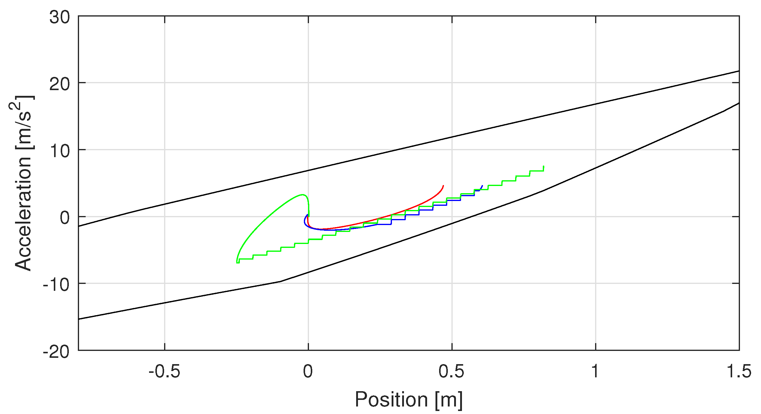
The obtained motion law is tested to verify that it respects the acceleration constraints. Three scenarios can be identified:
  • The acceleration limits are respected and the trajectory is feasible and does not require any changes;
  • The trajectory must be modified to respect the acceleration limits, but the end-effector stops at the SP;
  • The trajectory must be modified to respect the acceleration limits and the end-effector goes beyond the SP and has to return.
Figure 4 represents these scenarios: in red, a feasible trajectory, in blue, a trajectory that stops at the SP, and in green, a trajectory beyond the SP. As anticipated before, these three trajectories have different starting points.
If the resulting trajectory is feasible, i.e., the acceleration limits are respected, the motion law can be applied without any changes. However, since the other two cases do not respect the acceleration limits, the motion law should be adapted depending on the scenario.
  • Trajectory stopping at the SP:
    As the acceleration exceeds the limits, the value of acceleration adopted is set equal to the minimum limit in that position, instead of the one obtained from the polynomial motion law. While keeping the acceleration equal to the minimum value, it is possible to reach a point P along d that allows the end-effector to reach and stop at the SP if the acceleration is set as constant and equal to the minimum acceleration limit in that point. P can be identified since the position, speed and acceleration values are known. However, keeping a constant acceleration from P to SP means an abrupt change in the acceleration in P, which is not feasible. Therefore, a new polynomial law is defined starting from P to the SP, constraining the initial and final values of the position, speed and acceleration; the required time for this section can be estimated as the time needed to stop with constant acceleration. Moreover, this last section is also feasible, since it follows a constant acceleration motion law, which, in turn, is feasible.
  • Trajectory beyond the SP:
    For greater distances from the SP, after setting the acceleration value equal to the limit, it is not possible to identify a point P that allows the end-effector to stop at the SP with a constant acceleration. It is preferable to decrease the acceleration value, i.e., setting it equal to the minimum limit for each position, until the end-effector stops. Then, similarly to the initial situation, it is possible to design a fifth-degree polynomial motion law that stops the end-effector in the SP. Due to its definition, this second motion law does not assure to keep the acceleration value lower than the maximum acceleration limit, thus it is possible to identify again the three cases presented above. However, since the end-effector is nearer to the SP after this first trajectory, it is less likely that the required acceleration does not respect the acceleration limits.
The computed acceleration needed for the motion law is evaluated along d, therefore it should be expressed in the spatial reference system to be applied to the motors as
r ¨ = R T r ¨
which is the acceleration that should be used to control the end-effector in the absolute reference system.

4. Strategy Simulation

The recovery approach is here tested in a simulation model. A first goal is to make a comparison between the acceleration limits obtained with and without considering the actuators dynamics. Furthermore, the results shows the effectiveness of the proposed methodology.

4.1. Simulation Model

The simulation model was developed in Mathworks Simulink, representing both the cable robot and its controller. Two main parts were designed, focusing on the cable robot model and on the recovery strategy, respectively.
The cable robot model is defined as presented in Section 2, with the actuator torques as input data, evaluating their position and velocity, which allow to evaluate the wire length and velocity, as stated in (6). Moreover, the simulation environment presents additional outputs, i.e., the end-effector position in the absolute reference frame and velocity, which cannot be measured in an experimental phase, but must be evaluated using a direct kinematics algorithm.
The end-effector position and velocity along each reference axis is described by a linear system
v ˙ = F m b m v x ˙ = v
where v and x are the speed and the position of the end-effector, respectively, and F the exerted force. These equations can be expressed in matrix form as
v ˙ x ˙ = b m 0 1 0 v x + 1 m 0 F = A v x + b F
thus, from the three components of F, it is possible to evaluate the spatial position of the end-effector. F can be expressed as the vector sum of the cable forces, evaluated as
F i = u i τ i
where the unit vectors u i are evaluated from the structure matrix alongside the cable length l i , through
l i = a i r i
where a i and r i are the pulley position and end-effector position with respect to the absolute reference system respectively, with reference to Figure 1.
To simulate the recovery strategy, the algorithm first evaluates the time-instance at failure and which cable has broken. Subsequently, the recovery approach algorithm acquires all the information regarding the robot trajectory, i.e., the end-effector position, the cable length and velocity. The output of the recovery approach is represented by the acceleration of the end-effector r ¨ , both for the connecting path and straight line path in case of failure; the model then converts this output in the cable tensions and motor torques required for keeping the recovery trajectory.
Lastly, a feedback loop is required to know the end-effector position in every time-instance needed for the recovery approach to know the position corresponding to a certain value of the acceleration limits. The end-effector position is evaluated with a direct kinematics algorithm using the motor position, since it is impossible to measure it in the absolute reference system without introducing additional measuring systems.

4.2. Simulation Results

Table 1 represents the values adopted for the considered cable robot; these values have been chosen as an example and they do not change the main results presented in the model.

4.2.1. Motion Planning

Figure 5 represents the resulting maximum acceleration limits allowed when moving towards the SP from any point of the workspace. The chosen SP is chosen inside the residual SEW resulting from the failure of cable 3, with the spatial coordinates in the absolute reference system set as
x = 0.55 m y = 0.60 m z = 0.30 m
Figure 5a presents the maximum acceleration limits evaluated without considering the actuators’ dynamics, whereas Figure 5b represents the acceleration limits when considering the actuators constraints. The proposed method leads to lower acceleration limits, with a maximum acceleration equal to 28 m/s 2 , in comparison to the 35 m/s 2 obtained with the previous one. The two figures present a similar behaviour, i.e., smaller acceleration limits near the SP and maximum near the origin of the broken cable. This is due to the different cable configuration in the two zones: near the SP, the z component of the cable length vector l i prevails, therefore the cable tension does not contribute as much on the acceleration of the end-effector in the x y plane. On the contrary, near the origin of cable 3, the layout is more favourable for the planar acceleration. Since this behaviour depends only on the cable pose and not on their tension value, the proposed constraints do not affect it. Lastly, the limits are evaluated at the same quota of the SP for simplicity, but different heights lead to similar behaviour.
Similarly, Figure 6 represents the minimum acceleration limits allowed when moving towards the SP, with Figure 6a presenting the values obtained without considering the actuator dynamics, and Figure 6b the values obtained considering the proposed constraints.
The two figures can distinguish the boundaries of the static stability zone. Indeed, negative acceleration limits correspond to a static stability zone, since a perturbation of the end-effector will result in a static end-effector; whereas outside this area, i.e., with positive acceleration limit, the end-effector must be pulled towards the SP to stop it.
Lastly, Figure 7 represents the acceleration limits along generic lines directed towards the SP.
Each line is evaluated inside a spherical sector with a radius of 2.5 m, centered in SP and limited in the x y -plane between 0 and 45 and in the x z -plane between 0 and 10 . In the example, nine different directions d were considered, with the acceleration limits in each line evaluated at intervals of 0.05 m. Each figure represents, in the x -axis, the distance from the SP and, in the y -axis, the the acceleration values; the maximum acceleration limits are represented by the red lines, the minimum by the blue ones.
The off-line evaluation of the acceleration limits defines them as the minimum maximum acceleration limit and the maximum minimum one for several lines inside a sector of the workspace, and this is represented by the black lines in Figure 7. A comparison between the off-line and on-line evaluation of the acceleration limits is now perceivable, since the former imposes stricter limits, with a maximum difference of about 8 m/s 2 when constraining the actuator torque.
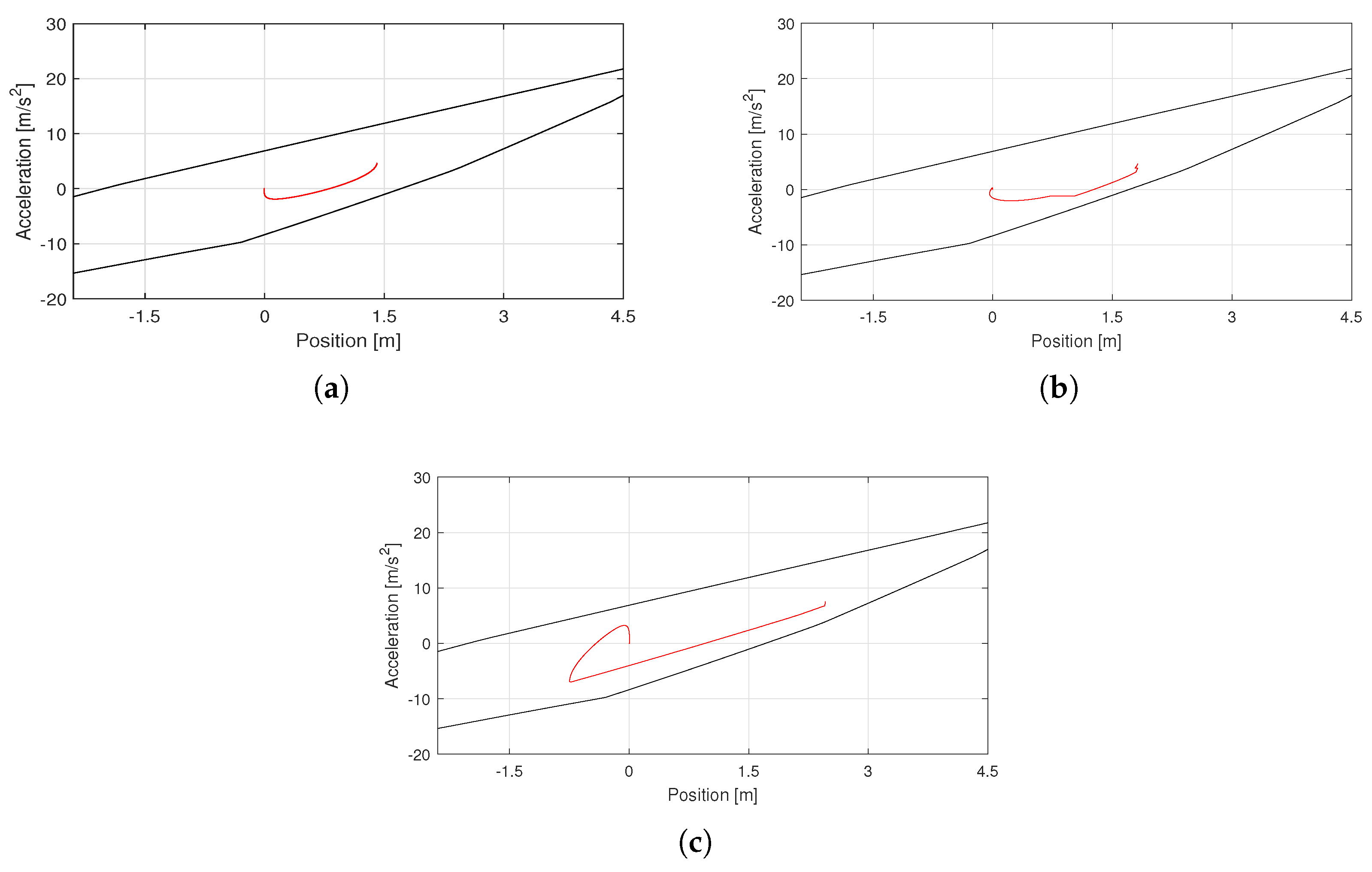
Regarding the motion planning, Figure 8 presents four different motion law, with an initial velocity of 0.64 m/s and incremental distances from the SP, respectively, 1.3, 1.7 and 2.2 m, chosen to represent the different cases presented in Section 3.3.
Figure 8a confirms that a polynomial law is sufficient to stop at the SP when the acceleration limits are observed, but as the distance increases, the limits are stricter. As observed in Figure 8b, indeed, when the acceleration value is equal to the inferior limit, its value is kept constant until it can follow a new polynomial law, stopping the end-effector before passing over the SP. However, in Figure 8c the end-effector must pass over the SP, thus initially stopping the end-effector at 0.7 m.
It should be noted that the discontinuous behaviour of the acceleration is due to the chosen resolution, which can be modified depending on the used system.

4.2.2. Robot Behaviour

As stated previously, the following results are provided when considering a failure in cable 3, when the end-effector position r and velocity r ˙ are, respectively,
r = ( 1.85 , 0.55 , 0.4 ) m r ˙ = ( 0.5 , 0.4 , 0 ) m / s
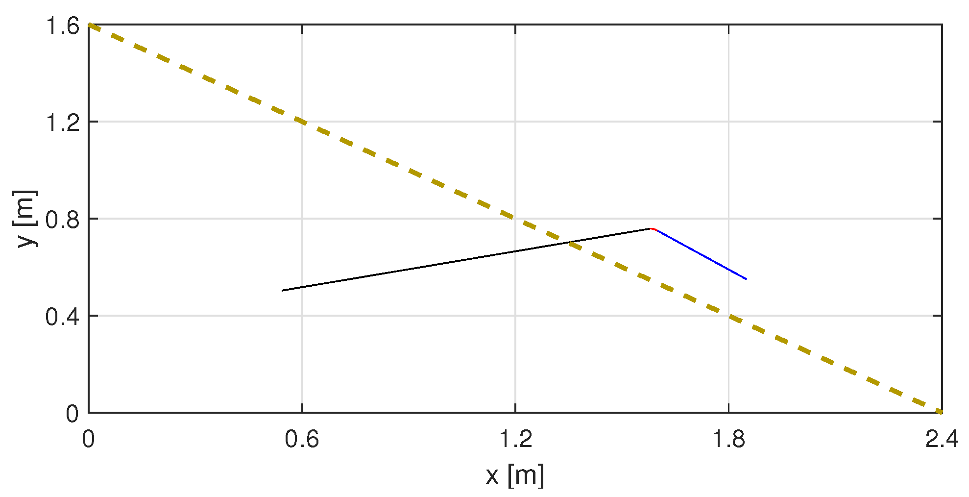
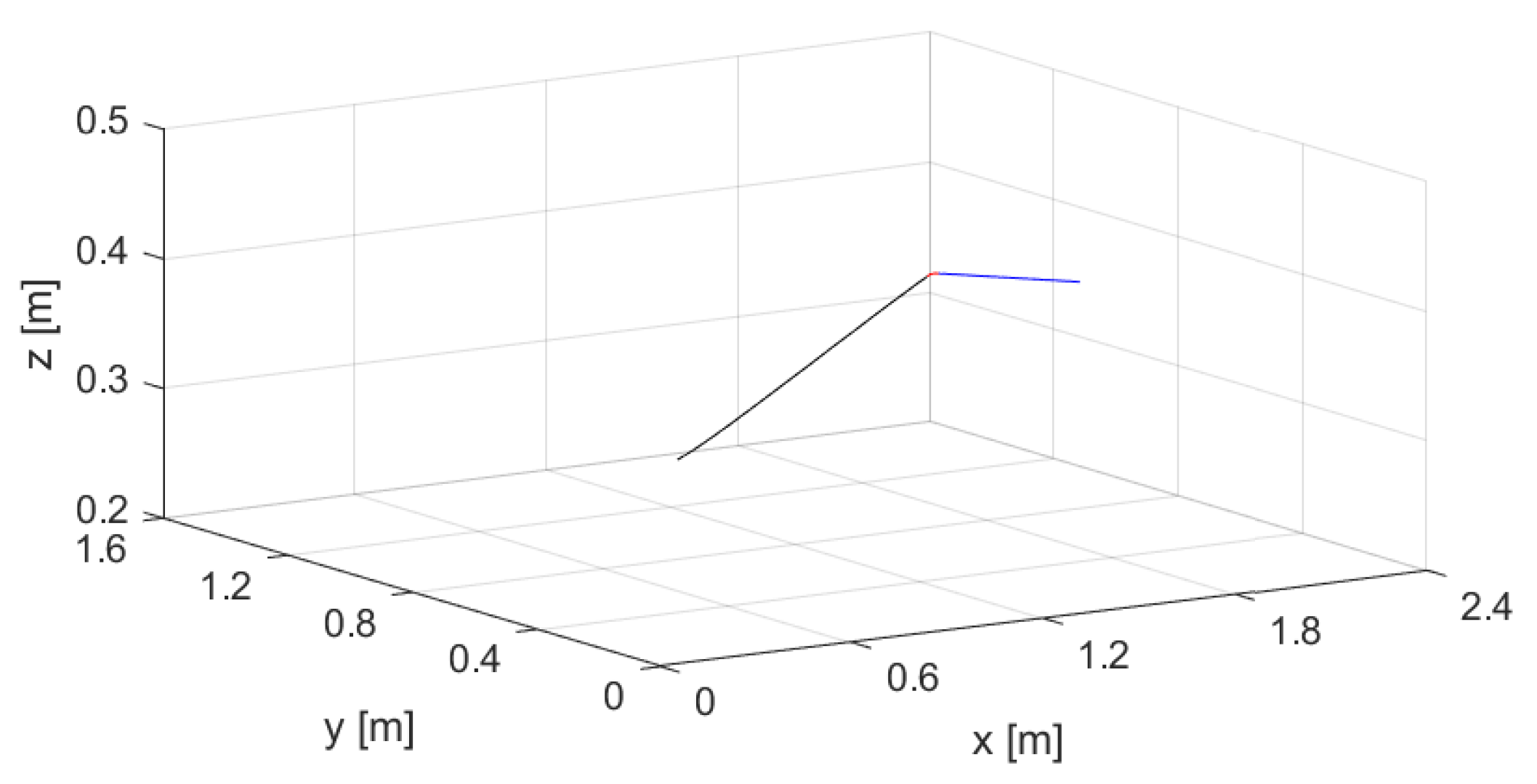
resulting in the aforementioned SP position placed at coordinates (0.55, 0.6, 0.3) m, thus allowing one to stop the end-effector at the SP without infringing the acceleration limits. The resulting trajectory can be observed in Figure 9 representing, in blue, the nominal trajectory before failure, in red, the Connecting Path, and in black, the linear path towards the SP; Figure 10 presents the trajectory in the x y z three-dimensional space. The dashed line in Figure 9 represents the boundary of the static stability zone.
The end-effector coordinates during the recovery approach are represented in Figure 11, adopting the RGB-color norm to represent the x (red), y (green) and z (blue) coordinates.
The three dashed lines identify the different phases of the recovery approach: the first one represents the linear motion before failure, followed by the Connecting Path and the straight line path in the third phase; the stationary end-effector at the SP concludes the motion. The recovery strategy affects all three coordinates and they all reach the respective SP coordinate in the same time.
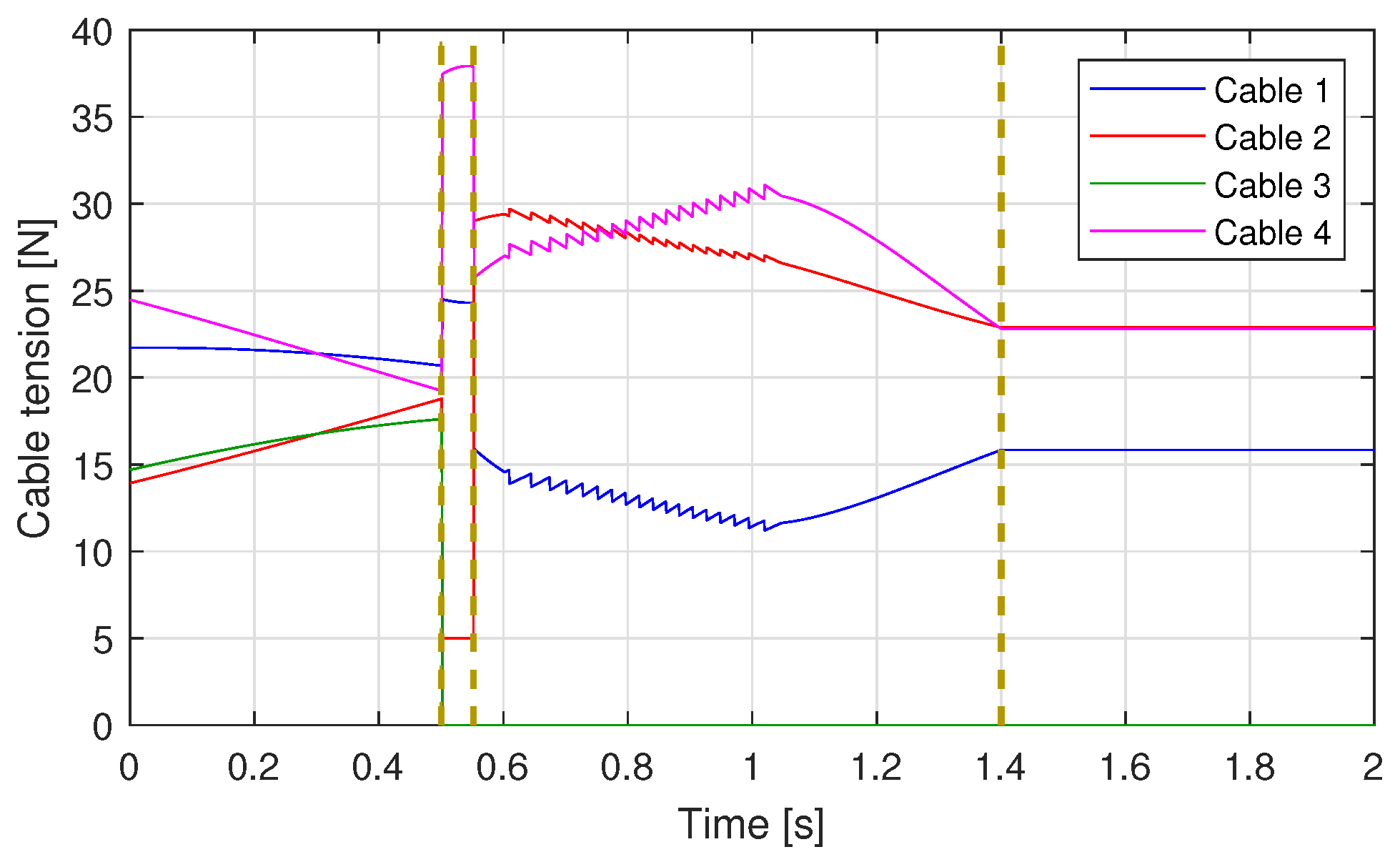
The different phases of the recovery approach can be observed also from the behaviour of the cable tensions observable in Figure 12.
The blue line represents the tension of cable 1, the red one, the tension of the cable 2, the green one, the tension of cable 3 and the violet one, the tension of cable 4. Focusing on the green line, it is possible to identify the temporal instance of the cable failure as the instant when the cable tension drops to 0. Thus, it is possible to distinguish the moment when the recovery strategy starts (0.5 s). At 0.5 s, we can observe a discontinuity in the cable tensions, due to the instant change in the robot stability; a second discontinuity takes place at the end of the connecting path, caused by the different values of acceleration at the beginning of the straight-line path, which is required to respect the acceleration limits along d.
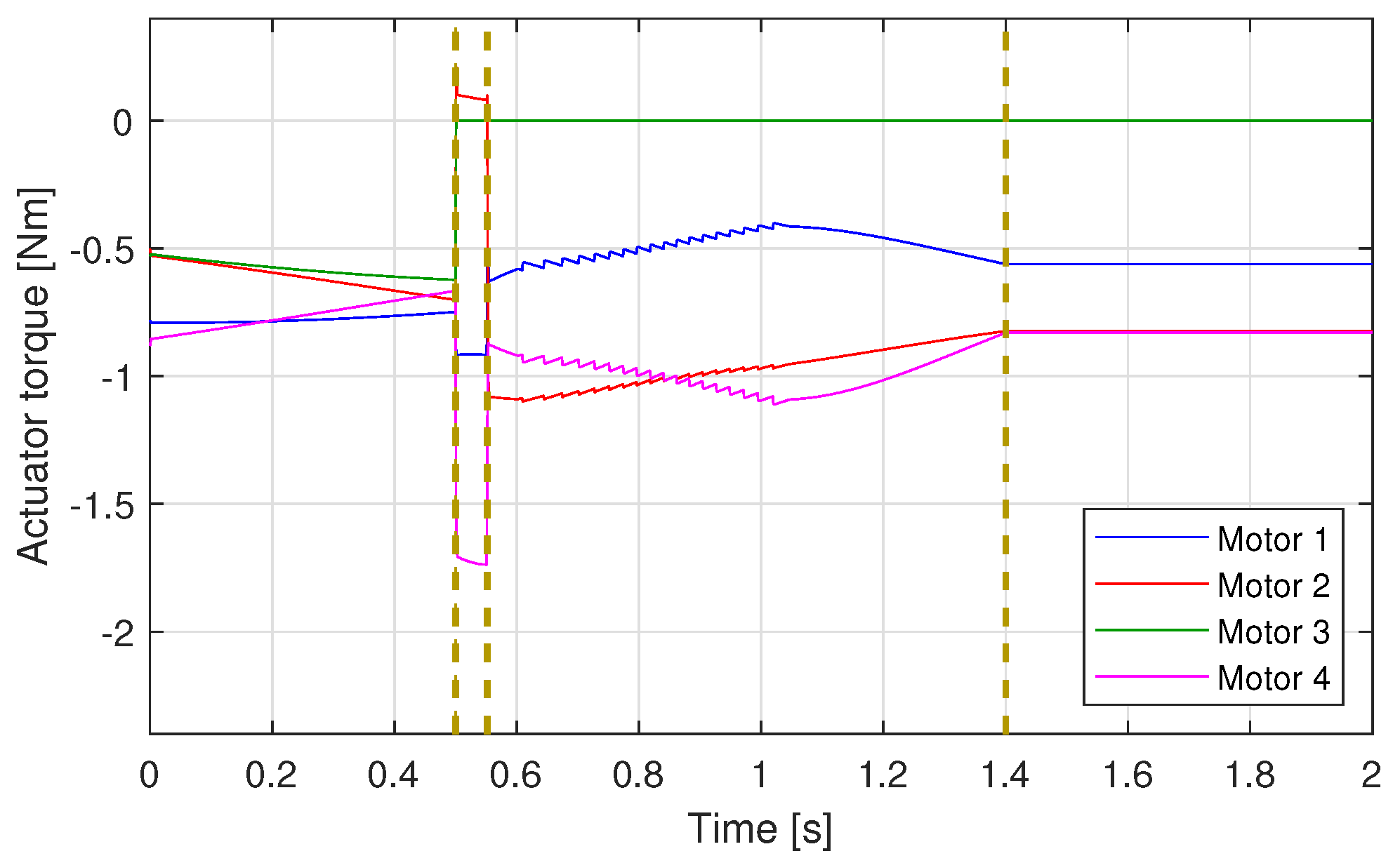
The actuator torques present a similar behaviour, as observed in Figure 13, with a similar color-code: blue for motor 1, red for motor 2, green for motor 3 and violet for motor 4. As the cable 3 fails, the motor torque of actuator 3 is equal to 0. A negative torque can be adopted with an appropriate strategy to recover the broken cable, further avoiding damage, however, such strategies are out of the scope of this work.
Motor 2 presents a positive, although small, torque and the adopted convention states that the cables are pulled only when the torques are negative, therefore a positive torque means that the end-effector should be pushed by the cable, which is unfeasible. However, the positive small torque is physically meaningful, since it is applied to compensate the friction and the motor inertia, allowing the actuator to be pulled by the other cables.
These behaviours were also observed for different tension and torque limits, showing how the proposed approach is affected by the imposed limits. The first tests reduced the maximum cable tension to 32 N (Figure 14a) and to 37 N (Figure 14b). Such lower limits, in comparison to the original one, affect the tensions behaviour, since they can no longer reach values over 37 N during the Connecting Path. Therefore, as seen in Figure 14, at the end of the connecting section, the end-effector position and velocity will be different between the two scenarios, thus influencing the robot behaviour during the linear path.
Similarly, different braking torque limits, i.e., −1.1 and −1.4 Nm, affect the end-effector behaviour during the straight-line path, as shown in Figure 15, respectively. In the first case, represented in Figure 15a, the torque of actuator 4 is set constant and equal to −1.1 Nm during the Connecting Path, whereas with a less strict torque limit, the torque initially decreases and then is again set constant and equal to the limit of −1.4 Nm. As seen previously, different behaviours during the first part of the recovery approach lead to different end-effector positions and velocity when starting the linear trajectory, thus leading to different torque values during the second part of the strategy.
By reducing the minimum torque, the duration of the Connecting Path, which is the most affected by the constraints on the actuator torques, increases by 13%, with a duration in the first scenario equal to 0.058 s and a duration of 0.051s with a less strict constraint. Lastly, similar behaviours are observed for different broken cables and initial end-effector position and velocity.
By looking at these simulations, it is clear that the proposed strategy allows the end-effector to reach the SP, while keeping, positive cable tensions for each set of parameters (minimum torque and maximum tension) during the whole recovery process.

5. Conclusions

This work presents an improved recovery strategy for cable robots. This method considers how the physics and dynamics of the actuator (i.e., the inertia, friction and torque limits) affect the robot behaviour. Moreover, the paper describes an iterative approach which is straightforward exploitable to industrial systems. A simulation model was tested to validate the feasibility of the proposed approach to move the end-effector towards a safe static position. Moreover, the simulation results show that the cable tensions are kept positive during the recovery process, and this proves the feasibility of the proposed method.
Future works will validate the proposed approach to prototypes, evaluating the efficiency and accuracy of the real-time approaches proposed and the effectiveness of the recovery strategy.

Author Contributions

Conceptualization, G.B., R.M. and A.T.; Investigation G.B., R.M. and A.T.; Methodology, G.B., R.M. and A.T.; Writing, G.B., R.M. and A.T. All authors have read and agreed to the published version of the manuscript.

Funding

This research received no external funding.

Conflicts of Interest

The authors declare no conflict of interest.

References

  1. Merlet, J.P. Parallel Robots; Springer Science & Business Media: New York, NY, USA, 2006; Volume 128. [Google Scholar]
  2. Bostelman, R.; Albus, J.; Dagalakis, N.; Jacoff, A.; Gross, J. Applications of the NIST RoboCrane. In Proceedings of the 5th International Symposium on Robotics and Manufacturing, Maui, HI, USA, 25–27 April 1994. [Google Scholar]
  3. Rosati, G.; Gallina, P.; Rossi, A.; Masiero, S. Wire-based robots for upper-limb rehabilitation. Int. J. Assist. Robot. Mechatronics 2006, 7, 3–10. [Google Scholar]
  4. Cone, L.L. Skycam-an aerial robotic camera system. Byte 1985, 10, 122. [Google Scholar]
  5. Ghaffar, A.; Hassan, M. Failure analysis of cable based parallel manipulators. In Applied Mechanics and Materials; Trans Tech Publications Ltd.: Aedermannsdorf, Switzerland, 2015; Volume 736, pp. 203–210. [Google Scholar]
  6. Bosscher, P.; Ebert-Uphoff, I. Wrench-based analysis of cable-driven robots. In Proceedings of the IEEE International Conference on Robotics and Automation, New Orleans, LA, USA, 26 April–1 May 2004; pp. 4950–4955. [Google Scholar]
  7. Notash, L. Failure recovery for wrench capability of wire-actuated parallel manipulators. Robotica 2012, 30, 941–950. [Google Scholar] [CrossRef] [Green Version]
  8. Boumann, R.; Bruckmann, T. Development of Emergency Strategies for Cable-Driven Parallel Robots after a Cable Break. In Proceedings of the International Conference on Cable-Driven Parallel Robots, Krakow, Poland, 30 June–4 July 2019; pp. 269–280. [Google Scholar]
  9. Berti, A.; Gouttefarde, M.; Carricato, M. Dynamic recovery of cable-suspended parallel robots after a cable failure. In Advances in Robot Kinematics 2016; Springer: Champaign, IL, USA, 2018; pp. 331–339. [Google Scholar]
  10. Riechel, A.T.; Ebert-Uphoff, I. Force-feasible workspace analysis for underconstrained, point-mass cable robots. In Proceedings of the IEEE International Conference on Robotics and Automation, New Orleans, LA, USA, 26 April–1 May 2004; pp. 4956–4962. [Google Scholar]
  11. Boschetti, G.; Passarini, C.; Trevisani, A. A recovery strategy for cable driven robots in case of cable failure. Int. J. Mech. Control 2017, 18, 41–48. [Google Scholar]
  12. Boschetti, G.; Trevisani, A. Cable robot performance evaluation by wrench exertion capability. Robotics 2018, 7, 15. [Google Scholar] [CrossRef] [Green Version]
  13. Lorenz, M.; Brinker, J.; Prause, I.; Corves, B. Power manipulability analysis of redundantly actuated parallel kinematic manipulators with different types of actuators. In Proceedings of the 2016 IEEE International Conference on Robotics and Automation (ICRA), Stockholm, Sweden, 16–21 May 2016; pp. 2129–2136. [Google Scholar]
  14. Boschetti, G. A Novel Kinematic Directional Index for Industrial Serial Manipulators. Appl. Sci. 2020, 10, 5953. [Google Scholar] [CrossRef]
  15. Boschetti, G.; Passarini, C.; Trevisani, A.; Zanotto, D. A fast algorithm for wrench exertion capability computation. In Cable-Driven Parallel Robots; Springer: Champaign, IL, USA, 2018; pp. 292–303. [Google Scholar]
  16. Carricato, M.; Abbasnejad, G. Direct geometrico-static analysis of under-constrained cable-driven parallel robots with 4 cables. In Cable-Driven Parallel Robots; Springer: Berlin/Heidelberg, Germany, 2013; pp. 269–285. [Google Scholar]
  17. Zhang, N.; Shang, W. Dynamic trajectory planning of a 3-DOF under-constrained cable-driven parallel robot. Mech. Mach. Theory 2016, 98, 21–35. [Google Scholar] [CrossRef]
  18. Pott, A.; Mütherich, H.; Kraus, W.; Schmidt, V.; Miermeister, P.; Verl, A. IPAnema: A family of cable-driven parallel robots for industrial applications. In Cable-Driven Parallel Robots; Springer: Berlin/Heidelberg, Germany, 2013; pp. 119–134. [Google Scholar]
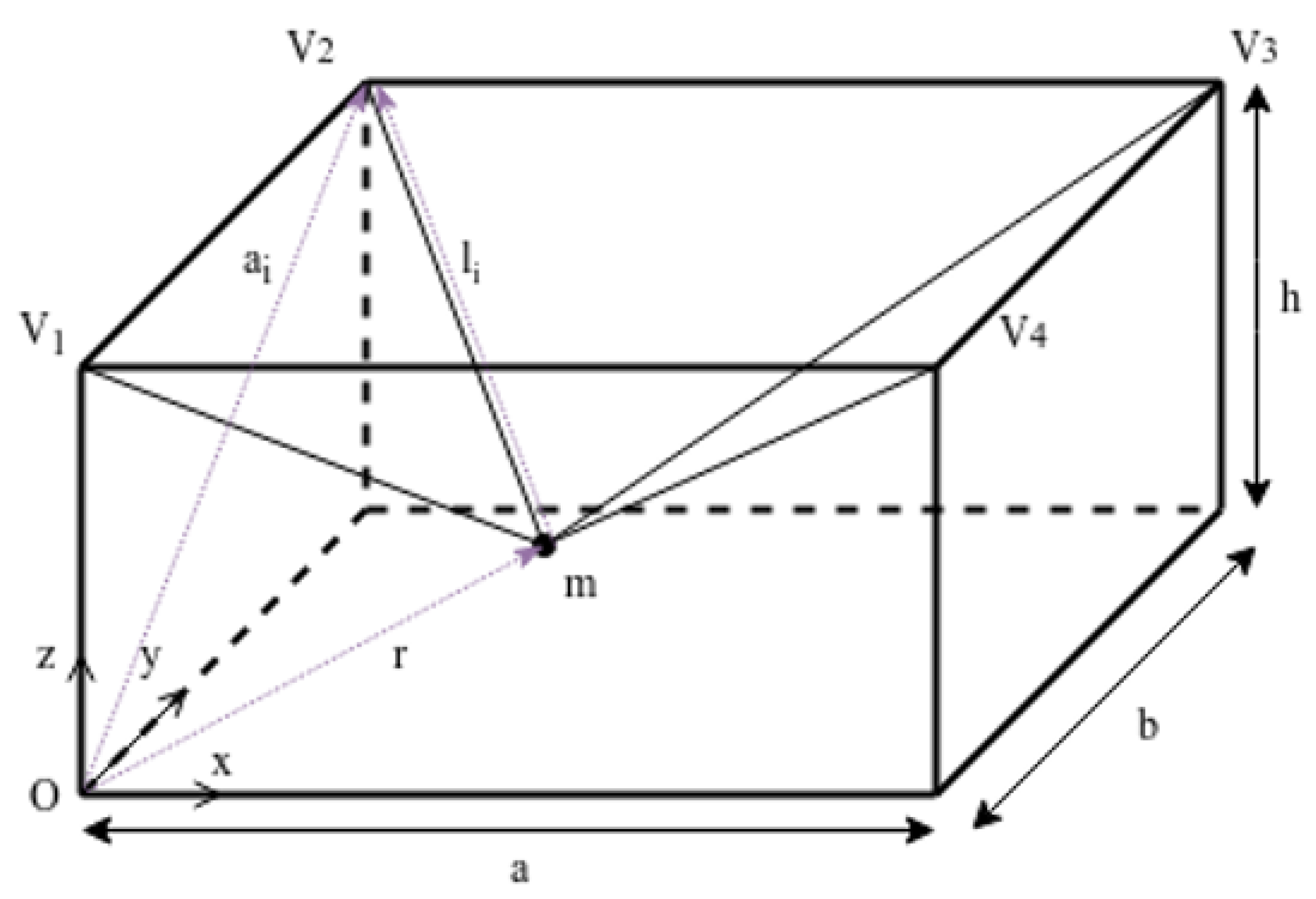
Figure 1. Structure of the considered suspended cable robot.
Applsci 10 07362 g001
Figure 2. 3d view of the velocity components (a) in the mobile reference frame and forces needed to change the velocity direction in the x y plane (b).
Applsci 10 07362 g002
Figure 3. Maximum and minimum acceleration values along d.
Applsci 10 07362 g003
Figure 4. Three different trajectories: depending on the starting point, to respect the acceleration limits, the trajectory is feasible (red), must be modified but the end-effector stops at the SP (blue), or goes beyond and must turn back (green).
Applsci 10 07362 g004
Figure 5. Comparison between the maximum acceleration limits obtained without considering the actuator dynamics (a) and considering the actuator dynamics (b).
Applsci 10 07362 g005
Figure 6. Comparison between the minimum acceleration limits obtained without considering the actuator dynamics (a) and considering the actuator dynamics (b).
Applsci 10 07362 g006
Figure 7. Comparison between the maximum acceleration limits (red) and minimum ones (blue) along a line d towards the SP obtained without considering the actuator dynamics (a) and considering the actuator dynamics (b).
Applsci 10 07362 g007
Figure 8. Motion law obtained with the proposed method when changing the distance from SP.(a) Distance: 1.3 m; (b) Distance: 1.7 m; (c) Distance: 2.2 m.
Applsci 10 07362 g008
Figure 9. Trajectory of the end-effector in the x y plane: in blue, the nominal trajectory before failure, in red, the connecting path and in black, the straight line path.
Applsci 10 07362 g009
Figure 10. Three-dimensional representation of the end-effector trajectory: in blue the nominal trajectory before failure, in red, the connecting path and in black, the straight line path.
Applsci 10 07362 g010
Figure 11. End-effector coordinates during the recovery approach: x (red), y (green) and z (blue).
Applsci 10 07362 g011
Figure 12. Cable tension during the recovery approach for cable 1 (blue), cable 2 (red), cable 3 (green) and cable 4 (violet).
Applsci 10 07362 g012
Figure 13. Motor torques during the recovery approach for motor 1 (blue), motor 2 (red), motor 3 (green) and motor 4 (violet).
Applsci 10 07362 g013
Figure 14. Cable tensions behaviour for different τ m a x limits. Cable 1 is represented in blue, cable 2 in red, cable 3 in green and cable 4 in violet. (a) Cable tensions for τ m a x = 32 N; (b) Cable tensions for τ m a x = 37 N.
Applsci 10 07362 g014
Figure 15. Actuator torques behaviour for different c m i n limits. Actuator 1 is represented in blue, actuator 2 in red, actuator 3 in green and actuator 4 in violet. (a) Actuator torque for c m i n = −1.1 Nm; (b) Actuator torque for c m i n = −1.4 Nm.
Applsci 10 07362 g015
Table 1. Values for the input parameters.
ParameterValueUnit
L 1 2.4 m
L 2 1.6m
h1m
m3kg
j m 5 × 10 4 kg m 2
b1.6 × 10 3 -
c m a x 2Nm
c m i n −2Nm
τ m a x 50N
τ m i n 5N
Publisher’s Note: MDPI stays neutral with regard to jurisdictional claims in published maps and institutional affiliations.