Abstract
Electric discharge machining (EDM) of tool steel (D2 grade) has been performed using different tool designs to produce through-holes. Machining performance has been gauged with reference to machining time, hole taper angle, overcut, and surface roughness. Inaccuracies and slow machining rate are considered as the most common limitations of the electric discharge machining (die-sinking). Traditionally, a cylindrical tool is used to form circular holes through EDM. In this study, the hole formation is carried out by changing the tool design which is the novelty of the research. Two-stage experimentation was performed. The newly designed tools substantially outperformed a traditional cylindrical tool, especially in terms of machining time. The main reason for the better machining results of modified tools is the sparking area that differs from the traditional sparking. Comparing against the performance of a traditional cylindrical tool, the newly designed tools offer a considerable reduction in the machining time, radial overcut, and roughness of the inside surfaces of machined holes, amounting to be approximately 50%, 30.6%, and 38.7%, respectively. The drop in the machining time along with a condensed level of radial overcut and surface roughness can shrink the EDM limitations and make the process relatively faster with low machining inaccuracies.
1. Introduction
Tool steels are high carbon and chromium content alloys used in a variety of industrial applications. D2 steel is one of the materials widely used in mold and die making industry. Forging dies, die blocks of die-casting, drawing dies, and different cutting tools are typical examples where D2 steel is used [1]. Such applications need to have various features to be produced through machining [2]. Blind and through-holes are one of the common features [3] and holes can be produced through electric discharge machining (EDM) [4].
The material removal mechanism of EDM is very complex and debatable due to the involvement of multiple factors. However, it is stated by the fundamental theories that the material removal is governed by the electrical conduction between both the electrodes. Heat is produced from the arc channels and immediately dissipated into the tool and work substrate. The result is melting, vaporization, and flushing of debris under dielectric action [5]. In this way, by the utilization of thermal energy, 2D and 3D features can be obtained. The formation of various kinds of holes is possible as per the shape of the tool, such as triangular, hexagonal, deep, inclined, blind holes, and through-holes. Such variety of holes is highly difficult by other single process, especially when the work material is hard metal or alloy [6]. Selection of the most appropriate tool material and electrode polarity play vital roles in the erosion mechanism of EDM [7]. Improvement in the performance of the EDM process can be realized by several methods such as employing different dielectric fluids, mixing of additives like boron carbide in the dielectric, polarity changing between tool and work sample, and rotation of electrodes [8]. Although EDM die-sinking is the widely used machining process in industry, it is a well-known fact that the machining rate of EDM is very low [9]. Machining inaccuracies in the form of overcut and tapered sidewalls, circularity, and undercut, etc. are other limitations of EDM [10,11]. To address these two issues, several researchers have worked in different directions to improve the machining rate and machining accuracy of EDM.
Seeking for the most appropriate tool electrode material for a particular or group of substrate materials is the foremost direction approached by researchers to get better machining results. For example, the brass electrode has been recognized as the most suitable material for EDM of a group of substrate materials including stainless steel, aluminum, and tungsten carbide if low tool wear [12] and low surface hardness [13] are the objectives. Rahul et al. [14] evaluated the EDM performance against different electrode materials such as copper, cryogenically treated copper, and tungsten and identified the suitable electrode resulting efficient material removal rate. Similarly, among four electrode materials (graphite, copper, brass, and aluminum), the copper electrode with negative polarity has been identified as the most suitable material to machine Ti6Al4V with minimum geometrical errors (radial and axial overcut) [15].
Optimization of machining parameters is one of the commonly used approaches to improve the machining rate and the feature accuracy [16,17]. For example, Kumar et al. [18] optimized the EDM parameters for the machining of aluminum boride composite and Singh et al. [19] performed multi-response optimization to deal with tungsten carbide samples. On similar lines, multi-objective optimization of EDM process parameters has also been attempted in another study to machine titanium alloy [20].
The use of different dielectrics and powder mixing in the dielectric is another route widely followed by numerous researchers to improve the machining rate of EDM and feature accuracies. In a study presented in [21], several dielectric mediums are tested to evaluate their performance on MRR. The authors used different combinations of dielectrics such as air, air–oxygen, distilled water–air, and distilled water–air–oxygen. An improvement of 6.6% in material removal rate and a reduction of 5.2% in tool wear rate can be realized through the addition of graphite powder during the powder mixed electric discharge machining (PMEDM) of tungsten carbide [22]. Jahan et al. [23] narrated that the machining of tungsten carbide with aluminum powder mixed in the dielectric result in higher MRR. Similarly, an increase of 12% in MRR have been reported by mixing graphene oxide flames in the dielectric [24].
The use of multi-hole electrodes in EDM sinking is also reported as promising choice to achieve close form tolerances and high material removal rate as compared to a conventional cylindrical electrode. However, it has been stated that the use of optimized parameters is required to get more benefit from a multi-hole electrode [25]. The use of composite tool electrodes (consisting of two different materials) is another emerging trend to improve the performance of the EDM die sinker. However, the investigations of the behavior of multi-material tool electrodes are at the initial stages and limited to the study of electric discharge breakdowns occurred between the anodes (tool and work) [26]. Multi-channel tool electrodes are found to have better drilling time, dimensional accuracy, and surface roughness during electric discharge drilling of Inconel 718 [27]. Changing the bottom profile of the tool electrode also affects the machining characteristics. Manohar et al. [28] compared the EDM performance using flat bottom and convex/concave bottom electrodes. A convex/concave shape at the bottom of electrode exhibits a thin recast layer, better surface finish, and machined geometries during EDM of nickel alloy. Other efforts to improve the EDM process performance are in the direction of assistive technologies and concepts. Some additional sources of energy assistance are combined with the primary EDM thermal energy. These include EDM with surfactant mixed dielectric [29], ultrasonic assisted machining [30], and magnetic stirring, etc. [31].
EDM is a very slow machining process and produces geometrical inaccuracies. It can be inferred from the literature that different efforts are being made to improve the machining rate and machining accuracy of EDM. Traditionally, a cylindrical electrode is used to machine holes through EDM die-sinking. In our previous study [32], relief angled electrodes were used for the first time to improve the machining performance of EDM to produce through-holes in tungsten carbide. With the use of relief angled electrodes, the machining time was significantly reduced (49% reduction) along with other machining characteristics. The process can be termed as relief angled electrode-based EDM. The goal of the present research is to study the relief angled electrode-based EDM process performance for D2 grade of steel and to validate previous results. Three different designs, i.e., conventional cylindrical design, relief angled design, and modified relief angled design, are introduced to produce through-holes in D2 steel. Each of the modified tool designs is further varied by providing different relief angles and land thickness. Machining time, hole taper angle, overcut, and surface roughness of machined holes are taken as the response measures. Performances of designed tool electrodes have been compared with the machining results corresponding to conventional cylindrical tool design. Two-stage experimentation is conducted to seek for an appropriate design having a potential of gifting better machining results.
2. Materials and Methods
Electric discharge machining (through die-sinking) of D2 steel has been carried out in this research. D-grades of tool steel are widely used materials in die-making industry. Typical applications include forging dies, die-casting blocks, and drawing dies. D2 tool steel is a widely used material in many applications. It has a high content of carbon and chromium as can be seen from its chemical composition provided in Table 1. Since electric discharge machining is a process in which electrical energy is converted into thermal energy and the material is eroded by melting of the electrodes (tool and work), the thermal and electrical properties of substrate materials are derived from the erosion phenomenon. The important properties of D2 steel, including thermal, electrical, and physical properties, are shown in Table 2. A D2 steel plate of 4 mm thickness has been used as a substrate and through-holes of 8 mm diameters are machined using copper electrodes.

Table 1.
Elemental composition of D2 steel [33].
Table 2.
Physical, mechanical, and thermal properties of tool steel D2-grade [34].
2.1. Electrode Designs and Fabrication
The tool electrodes used in this work are made of copper, as the cooper electrode has been widely used as a suitable tool electrode for the EDM of tool steels. Three different tool designs are used to machine through-holes in the substrate. Additionally, drilling a circular hole through the EDM die sinker is carried out using a traditional cylindrical electrode, as it has a uniform cross-sectional area. One of the tool designs used in this research is a conventional design represented as DC. It consists of an 8 mm face and shank diameter and height of 50 mm. The second design is named the relief angled tool design and is denoted as DR. In this type of design, taper turning is performed from the tool face up to a certain length to develop a relief angle at one end of the tool. The remaining tool length is simply turned to develop a shank as can be seen in Figure 1b. The diameter of the face remains at 8 mm while the diameter of the shank is kept at 5 mm. In this way, two lengths are generated and named “face height” and “shank height”. These heights are such that the overall length of the tool remained at 50 mm as in the case of the conventional design. The face diameter is also kept at 8 mm. The third type of design is the modification of the second design and is named as relief angle with land and denoted as DRL. In this design, the tool is the same as that of the relief angle design except the tool face. In the case of the relief angle design, the taper starts immediately at the end of the face, whereas, in the case of DRL, the taper starts after 1 mm distance from the tool end, leaving the end with 1 mm thickness as is schematically illustrated in Figure 1c. This 1 mm thick end is named as land. The face diameter is again 8 mm and shank diameter is 5 mm. The only difference is in the length of its different sections. However, the total length of the tool is kept at 50 mm. It must be noted that with each of the two designs, DR and DRL, five sub-designs are developed by varying the angle of taper (relief angle). Schematics of each of the sub-designs are shown in Figure 2. Relief angles of 5°, 10°, 20°, 30°, and 45° are provided in each tool. Full details of each design are provided in Table 3. Hence, in this way, EDM was performed with one conventional tool and 10 newly designed tools. All the tools were prepared from the same rod of copper having an initial diameter of 10 mm. The tool preparation is carried out under the constant and same machining conditions.
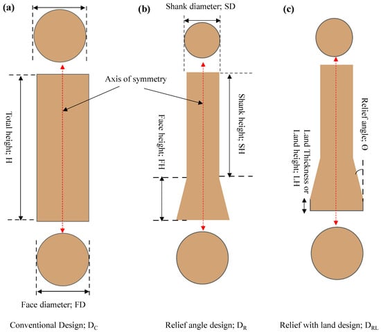
Figure 1.
Schematic of electrode designs; (a) conventional, (b) relief angled, and (c) relief with land.
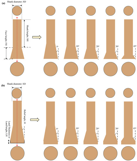
Figure 2.
Schematic of electrode designs; (a) sub-designs of DR, and (b) sub-design of DRL.
Table 3.
Electrode designs with dimensions.
2.2. Electric Discharge Machining Conditions
All the experiments are performed on D2 steel with copper electrodes. All the machining conditions are kept constant for each experiment such as discharge current (30 A), spark voltage (5 V), pulse on-time (100 µs), pulse off-time (50 µs), and dielectric (kerosene oil), etc. The only variable is the tool design so that the effect of tool designs can be categorically and clearly examined without the influence of machining parameters. That is why all the EDM parameters are kept constant. The alignment of the substrate over the worktable plays an important role is successful EDM and the tool axis must be perpendicular to the substrate’s top surface. For this purpose, the work sample was ground to eliminate the unevenness of the work surface surfaces. Perpendicularity between the tool and work was carefully ensured.
2.3. Machining Responses and Measurements
Four important machining responses are taken into consideration to evaluate the machining performance of different electrode designs. These responses are machining time (MT), hole taper angle (ø), radial overcut (ROC), and surface roughness (SR) of the inner walls of the machined holes. Each of these performance measures against each of the 10 improved designed electrodes were compared with the performance of conventional tool design (cylindrical tool). Machining time was measured with the help of a stopwatch.
The measurements of the hole dimensions were performed with coordinate measurement machining (CMM) having a least count of 1 µm. Hole diameters at the entry and exit planes were measured by six-point measurements and average diameters were recorded. Hole taper angle was calculated by the use of entry and exit diameters. Since during EDM, the machined feature is always larger than the tool size due to erosion and crater formation, radial overcut (ROC) is taken as one of the response measures in this work. It is calculated from the diameter of the machined hole and diameter of the tool electrode [32]. The difference of these two diameters is termed as radial overcut. Tool diameter was measured for three times through screw gauge and average value was taken for the ROC calculations. The roughness of the machined surfaces was measured by the Surtronic surface roughness meter using 3 mm evaluation length. Three readings for surface roughness were taken at different regions and average values are reported. All the roughness values are presented in terms of Ra.
2.4. Experimentation and Analysis
In this research, a two-stage experimentation has been performed. In the first stage, 11 experiments were performed as per the tool designs presented in Table 3. The performance of each tool design is compared with the conventional cylindrical tool in terms of four response characteristics (MT, ø, ROC, and SR) with the help of simple bar charts. The suitable electrode design is identified to be capable of giving the best result for each response. In this way, the most appropriate tool design(s) is/are identified capable of dealing with all the four responses. The second stage of experimentation was further planned based on the identified tool designs (DC, DR, or DRL) and relief angle. In this second stage, two levels of most appropriate relief angles and three levels of land thickness were taken as the design variables. In this way, six more experiments were performed to statistically evaluate the effect of relief angle and land thickness. The significance of each variable is accessed through main effect plot and analysis of variance. Details and the rationale of second stage experimentations are provided and explained in subsequent sections.
3. Results and Discussion
In this section, experimentation on EDM of D2 steel (stage 1), results, and discussion are presented. From the outcomes of stage 1 experimentation, experimentation on D2 steel is further extended and stage 2 was planned and performed. Results and discussion pertaining to the second stage of experimentation are explained in Section 3.6.
EDM die-sinking of D2 steel has been performed using several tool designs. The primary design is the conventional design (DC), which is a cylindrical shape. The other two main designs are relief angle design without land (DR) and the design having relief angle with land (DRL). Machining results belong to each of the four response characteristics are assembled in Table 4. It can be seen that the response values are greatly affected by different designs. For instance, the time taken to complete the through-hole in D2 steel varies from 11.2 to 22.2 min, and hole taper angle varies from 2.3° to 13.8°. Some of the machined holes are shown in Figure 3.
Table 4.
Experimental results of EDM of D2 steel (1st stage of experimentation).
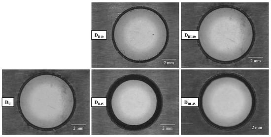
Figure 3.
Machined holes produced through different electrode designs (DC, DR, and DRL).
3.1. Analysis of Machining Time (MT)
The effect of electrode designs on the time taken to complete the through-hole of 4 mm depth is presented in Figure 4. The cylindrical tool (DC) completed the desired hole in 22.25 min. This response has been taken as a reference to compare the machining time taken by other electrode designs. As can be seen that when the machining is performed by newly designed tools, there is significant reduction in machining time taken by all the electrodes compared with the time taken by cylindrical electrode. Among the relief angled design (DR), the time value ranges from 11.27 to 17.4 min. Five relief angles are varied within design type DR. It can be observed that the time taken by 5° and 10° tools is close to each other since the change in the value of relief angle is very small. However, with the further increase in relief angles (20°, 30°, and 45°), the machining time gradually increases.
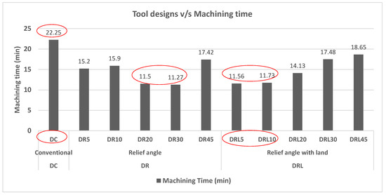
Figure 4.
Effect of electrode designs on machining time.
For example, the tools with 5° and 10° relief (DR5 and DR10) complete the hole in approximately 15.5 min and the time taken by 30° relief is found to be 11.2 min. However, against the higher relief angles like 45°, the time tends to increase (17.2 min). Within the sub-designs of DR, the tools having 20° and 30° angles offer the lowest machining time (~11.3 min). The next design type, i.e., DRL, follows the similar pattern. Within this design, DRL5 and DRL10 consumed almost equal time (~11.6 min). After 20°, the time taken by relief with land tools increases. Among the sub-designs of DRL, the minimum time has been observed in the case of 10° and 20° relief amounting to be ~11.6 min. However, the time taken by 30° and 45° reliefs are somewhat closer to each other. Comparing the results with conventional tool design, approximately 50% reduction in machining time can be achieved during EDM of D2 steel using the novel designs of electrodes. It can be considered as an appreciable contribution in the field of electric discharge machining. Whenever the use of EDM is avoided in the industry, its low machining rate is one of the major factors. The use of newly presented electrode designs has the potential to substantially reduce the machining time, and ultimately, the productivity of EDM can be improved.
The phenomenon behind this reduction in erosion time is believed to be a different sparking behavior in the case of altered tool designs as compared to sparking offered by conventional design since the erosion is carried out by electrode surfaces close to the substrate surfaces. At the initial cuts, the erosion phenomenon is the same for all the designs. Electric discharges are only produced between the electrode’s bottom face and the top surface of the work sample. However, as the hole formation progresses, the sparking occurs at two regions, i.e., at the tool’s bottom face and around the periphery of the tool’s segment penetrated inside the partially formed hole. The conventional cylindrical tool design has straight vertical walls throughout its length (face and shank diameters are equal, i.e., 8 mm). Thus, the sparking area continuously increased in case of conventional design (DC). However, the design with relief angle (DR) allows the electric discharges to be produced just at the machining end of the tool. The presence of relief angle prevents the peripheral sparking since the face diameter is of 8 mm and the shank diameter is of 5 mm (refer to Figure 1). In the presence of relief angle, the inter-electrode gap between the shank and inner walls of the hole gets so high that sparking does not occur. Thus, the same input energy is focused at the bottom face of the tool, leading to high energy density. As a result, the machining time is soundly reduced. In the case of the third design (DRL), the sparking area also remains constant but less than the sparking area observed with the cylindrical electrode. Sparking occurs at the footing end and at the 1 mm land area. It remains constant until the complete hole is produced. On the other end, since the sparking area continuously increased by the cylindrical tool; therefore, the same amount of input energy is consumed to erode larger areas, and as a result, more time is taken to complete the hole.
3.2. Analysis of Hole Taper Angle (ø)
Obtaining straight walls of the features machined though EDM is highly difficult. The effects of tool designs over the hole taper angle are shown in Figure 5. The hole produced by cylindrical electrode has a taper of 2.34°. As the relief angle increased from 5° to 45°, there is a consistent increase in the hole taper angle. This degree of increase is more prominent in case of relief angle tool design (DR) as compared to the taper angles resulted by relief angle with land design (DRL). The reason behind the difference in design. Since the electrodes within the category of DR have tapered faces and the relief angle starts immediately from the ending face, the greater the relief angle, the greater the taperness in the tool. A relief angle without land could not maintain its cutting face diameter. Thus, as the tool length is consumed during the formation of hole, the final diameter of the tool face gets reduced as compared to the diameter at the start of the hole formation. Consumption of tool length causes the hole to be narrower at the exit plane and the result is the enlarged hole taper angle. On the other side, the design type DRL consists of 1 mm land and the relief angle in the tool does not start at the bottom face but after 1 mm distance from the face. Therefore, during the tool length reduction, the diameter of the face is not seriously affected and the variation in the hole taper is not as prominent as in the case of design type DR. This was the main reason of designing the third type of tool design (DRL) by modifying the design type DR.
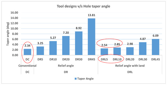
Figure 5.
Effect of electrode designs on taper angle of machined hole.
Among the taper angles observed in all the machined holes, the hole produced by conventional electrode has a minimum degree of taperness (2.34°). However, the hole taper angles associated with tool designs DRL5 and DRL10 seems to be comparable with the taper angle associated with conventional design DC. From here, it can be noticed that if the tool designs DRL5 and DRL10 offer good results with respect to other machining responses, these two designs can then be considered as the most appropriate tool design. The taper angles of these two designs are close to the hole taper angle corresponding to the conventional tool; there is only 0.2° difference (8.5%) between the hole taper angles produced by DC and DRL5.
3.3. Analysis of Radial Overcut (ROC)
It is a common effect of EDM process that the machined internal feature is slightly oversized as compared to the tool dimensions. Therefore, in this research with reference to hole formation it is named as radial overcut (ROC). It is a difference between the hole’s entry diameter and the diameter of the tool electrode. The effects of tool designs over ROC are presented in Figure 6. The value of ROC against the conventional cylindrical tool is found to be 464.50 µm, indicating that the hole size is greater than the tool size by the said amount. Comparing the radial overcuts observed during the use of newly designed electrodes, all the electrodes within the category of DR type design have less ROC as compared to the DC design. No uniform trend has been observed. However, among these five designs of DR type, the design with 5° relief (DR5) gives the minimum value of ROC. On the other side, the design type DRL offers continuous increase in radial overcut when the relief angles changes from 5° to 45°, except in the case of 10° relief. Even the radial overcut by 30° and 45° relief angles is higher than the overcut caused by conventional design. However, 322 µm is the minimum overcut resulted by the electrode nominated as DRL5, as highlighted by the oval-shaped callout. Comparing this value with the overcut caused by conventional cylindrical tool (464.50 µm), a 30.6% reduction in overcut can be realized by the use of newly designed tool (DRL5).
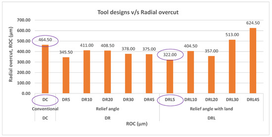
Figure 6.
Effect of electrode designs on radial overcut of machined hole.
The resistance in a current carrying conductor is a function of conductor’s length, cross sectional area, material, and other factors. Therefore, it is believed that the resistance in the designed electrodes changes because of the varying cross-sectional areas. As a result, the current characteristics may be changed. This could be the reason behind this irregular pattern of radial overcut. The present research is on its initial stages to see the effects of novel tool designs in the field of electric discharge machining. However, further research is necessarily needed to evaluate the variation in the resistance, current density, and flow characteristics of the discharge current when the electrode design is changed.
3.4. Analysis of Surface Roughness (SR)
Roughness of the inside walls of the machined holes is compared through bar chart as shown in Figure 7. The roughness generated by cylindrical tool is found be 13.7 µm. Most of the newly designed tools offer low surface roughness compared to the conventional tool design. Tool designs with 30° relief angle produced holes with high surface roughness. However, among all the tool designs, a relief angle of 10° with land of 1 mm (DRL10) offers the minimum value of surface roughness 8.4 µm. In comparison with the roughness corresponding to conventional tool design, it can be stated that a 38.7% reduction in the surface roughness can be realized if the holes are machined with DRL10 tool design. The second lowest member is the 5° relief (DRL5), resulting in 10.1 µm roughness as indicated by oval callout in Figure 7. No regular pattern of surface roughness is observed with the change in relief angle. The reason behind this irregular pattern is believed the same as discussed in Section 3.5.
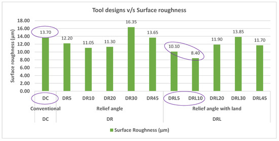
Figure 7.
Effect of electrode designs on surface roughness of machined hole.
3.5. Summary of Stage 1 Experimentation
Summary of results pertaining to stage 1 of experimentation is presented in Table 5. The minimum value of each of the four responses (machining time, hole taper angle, radial overcut, and surface roughness) is considered as the decision criteria. Three tools are ranked as rank 1, rank 2, and rank 3 based on their experimental values associated with each response. Tool with rank 1 indicates that it offers the minimum of response value, whereas the tool with rank 2 indicates the response value immediately higher than the value against the first ranked tool, and the tool with rank 3 indicates the value immediately higher than the value against the second ranked tool. Two electrodes, DRL5 and DRL10 with relief angles 5° and 10°, are found to be the most common. Similar results have also been proved in the case of electric discharge machining of tungsten carbide through the use of relief angled electrodes [32]. Hence, among the overall three designs (DC, DR, and DRL), the electrode design having relief angle with land (DRL) is relatively more promising. Hole taper angle and machining time may be considered as the important performance measures. Both of these tools are found be highly comparable with the conventional cylindrical tool as well as in a close completion with each other. Thus, the second stage of experimentation was planned to see that whether the effect of these two relief angles over the response measures is statistically significant or not.
Table 5.
Summary table to extract suitable design.
3.6. Experimentation of Stage 2
Since there is a close competition between the performance of 5° and 10° relief angles, therefore stage 2 of experimentation was also planned and executed. In stage 2, two relief angles (5° and 10°) are selected as a variable and evaluation is done based on statistical analysis such as ANOVA and main effects plots. Similarly, the land thickness is also taken as a variable with three levels, i.e., 2 mm, 3 mm, and 4 mm. The objective was to evaluate the effect of land thickness on the machining performance. In order to benchmark the performance of relief angled tools, one experiment with conventional cylindrical tool was also performed. Experimental results are shown in Table 6.
Table 6.
Experimental results of stage-2 experimentation.
3.6.1. Descriptive Statistics
In order to get an overall analysis of experimental results of stage 2, descriptive statistics are determined. In this list of descriptive statistics, five measures are taken for each of the four responses. The list of descriptive measures includes mean, standard error of mean, standard deviation, minimum value of each response, and maximum value of each response as shown in Table 7.
Table 7.
Statistics of machining responses.
3.6.2. ANOVA
The p value is considered as the most important indicator of significance evaluation. The p value < 0.05 indicates that the factor significantly contributes to the results; otherwise, the factor’s influence is insignificant. ANOVA for each response was conducted and the results in consolidated form are presented in Table 8. As it can be seen that for the case of machining time, the p value against relief angle and land thickness are greater than the threshold value of 0.05. Hence, it can be stated that the effect of relief angle (by varying relief from 5° to 10°) and land thickness (by varying land from 2 mm to 4 mm) is statistically non-significant on the machining time. Likewise, p values of both the relief angle and land thickness is found to be higher than qualifying value of 0.05 for all the remaining three responses. Thus, the effect of relief angle (within 5–10°) and land thickness (within 2–4 mm) is statistically non-significant. It means that whether the response values are different in different cases of relief angles and land thickness but the difference in values is statistically insignificant and do not seriously affect the process performance.
Table 8.
Analysis of variance for machining responses.
3.6.3. Main Effects Plot Analysis
The main effect plot corresponding to the machining time is shown in Figure 8a. It can be observed that the effect of relief angle over the machining time is inversely proportional. As the relief angle is increased from 5° to 10° the machining time is reduced. However, this reduction in machining time is found to be statistically insignificant as per ANOVA results. On the other end, less amount of land thickness seems to be better in order to produce holes. The increase in land thickness takes longer time to complete the erosion of through-holes. However, again, the extra time taken by the larger land thickness is statistically insignificant. It can be stated that any of the relief angle between 5° to 10° and any of the land thickness among 2, 3, and 4 mm can be taken to reduce the machining time. However, the tool with 10° relief and 2 mm land thickness takes relatively less machining time to complete the hole through EDM.
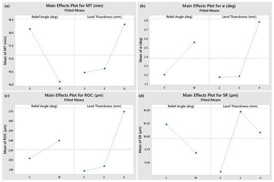
Figure 8.
Main effects plots of machining performance measures; (a) machining time (MT), (b) taper angle (ø), (c) radial overcut (ROC), and (d) surface roughness (SR).
Main effects plot for hole taper angle against relief angle and land thickness is shown in Figure 8b. As the relief angle is increased from 5° to 10° the hole taper angle also increases but this increase is not significant as determined by ANOVA tests. For example, the mean values of hole taper angles are approximately 2.2° and 2.5° when the relief angle is changed from 5° to 10°. Likewise, the effect of land thickness over the hole taper angle is directly proportional. As the land thickness is increased the taper angle of the machined hole also gets increased. But this increase is statistically insignificant. However, the relief angle of 5° and land thickness of 2 mm produce smaller taper angle.
Hence, the tool with 5° relief and 2 mm land thickness can be selected as the most appropriate tool design in order to achieve minimum hole taper angle during EDM of D2 steel.
The main effect plot associated with radial overcut (ROC) is shown in Figure 8c. The mean value of ROC follows directly proportional trend against each variable. Since the change in overcut is statistically insignificant, therefore those levels of relief angle land thickness should be chosen capable of resulting low overcut. As per the graph, 5° relief angle and 2 mm land thickness could be the preferred choice.
The main effects plot of surface roughness is shown in Figure 8d. It can be seen that the roughness of the inside walls of machined holes gets reduced when the relief angle of 10° is provided in place of 5°, whereas the increase in land thickness makes the machined surface rough. However, it must be noted that the difference in surface roughness observed in main effect plots is statistically not significant as proven during ANOVA results. Thus, it can be stated that any of the relief angle and land thickness values can be chosen for modified tool design but a land thickness of 2 mm can produce holes with low value of surface roughness. It can be deduced from main effect plots that a bigger than necessary land thickness may result into reduced machining performance in terms of radial overcut, hole taper angle, surface roughness, and machining time.
3.6.4. Summary of Stage 2 Experimentation
From the stage 2 of experimentation performed for D2 steel, it can be inferred that the effect of relief angle (within 5° to 10°) and land thickness (within 2 to 4 mm) over each of the four response measures is statistically insignificant. It indicates that any of the relief angle from 5° to 10° and any of the land thickness from 2 mm to 4 mm can be taken to machine the holes on D2 steel. If the machinist needs to opt one electrode design then design type DRL is the most suitable design. Moreover, relief angle of 10° and land thickness of 2 mm can be considered as the most appropriate choice since it gives relatively better machining results.
4. Conclusions
Electric discharge machining (EDM) of D2 steel has been performed to produce circular holes with different electrode designs under constant machining conditions. Two-stage experimentation was performed using several tool designs. EDM results with reference to machining time (MT), hole taper angle (ø), radial overcut (ROC), and surface roughness (SR) are compared with conventional cylindrical tool design. Based on the results and discussion, following important conclusions can be established:
- During the EDM of D2 steel, relief angled tool electrode performs better than the traditional cylindrical electrode.
- In comparison with the cylindrical electrode (DC) the modified tool designs (DR and DRL) complete the through-hole in substantially shorter time. Approximately 50% time can be saved by the use of electrode design DRL. Minimum time taken by DC and DRL tools is 22.25 min and 11.72 min, respectively.
- Taper angle (ø) of the eroded hole increases with the increase in relief angle. The conventional cylindrical tool produces hole with minimum taper angle of 2.34°. However, the tool having relief with land (DRL) creates 2.54° taper indicating that DRL design can also be considered in place of conventional design.
- Tool design having relief with land (DRL) offers lowest value of radial overcut (ROC) amounting to be 322 µm. Comparing with the overcut caused by conventional cylindrical tool (ROC = 464.50 µm), a 30.6% reduction in overcut can be realized.
- Most of the relief angles produce holes with smaller surface roughness as compared to traditional tool (DC). The smallest surface roughness against DC and DRL designs are 13.7 µm and 8.4 µm respectively. Compared to conventional electrode, a reduction of 38.7% in surface roughness can be realized by the use of DRL.
- Among the three main electrode designs (DC, DR, & DRL), the design having relief angle with land (DRL) offers less machining time, radial overcut, and surface roughness of the machined holes.
- There is a close competition between the performance of 5° and 10° relief angles. The influence of the relief angle (between 5° & 10°) on all the four machining responses is found to be statistically insignificant. However, 10° relief angle could be the most preferred choice to get better machining results.
- The effect of land thickness (within 1–4 mm) over the machining responses is statistically insignificant, however land thickness gets consumed during machining therefore it should be just enough to withstand the machining process till completion.
- Relief angled electrode based EDM is at its very initial stage and extensive future research on this topic is expected to be carried out in several domains such as modeling of spark area and material removal rate, tool wear rate phenomenon, performance of relief angled electrode based EDM over difficult-to-machine materials, and further modifications in electrode designs etc.
Author Contributions
Conceptualization, M.R. and N.A.M.; Data curation, M.R.; Formal analysis, M.R., N.A.M. and N.A.; Funding acquisition, N.A. and A.M.A.; Investigation, M.R. and A.H.; Methodology, N.A. and A.M.A.; Project administration, A.M.A.; Resources, N.A.M., N.A., and A.H.; Software, M.R. and A.H.; Supervision, N.A.M.; Validation, A.M.A. and A.H.; Writing—original draft, M.R., N.A.M. and N.A.; Writing—review & editing, A.M.A. and A.H. All authors have read and agreed to the published version of the manuscript.
Funding
Raytheon Chair for Systems Engineering, King Saud University, Saudi Arabia.
Acknowledgments
The authors are grateful to the Raytheon Chair for Systems Engineering, King Saud University for funding.
Conflicts of Interest
The authors declare no conflict of interest.
References
- D2 Steel Properties. Available online: https://www.steelexpress.co.uk/toolsteel/D2-Steel-properties.html (accessed on 31 January 2020).
- Campi, F.; Favi, C.; Mandolini, M.; Germani, M. Using design geometrical features to develop an analytical cost estimation method for axisymmetric components in open-die forging. Procedia CIRP 2019, 84, 656–661. [Google Scholar] [CrossRef]
- Vipin; Kant, S.; Jawalkar, C.S. Parametric Modeling in Drilling of Die Steels using Taguchi Method based Response Surface Analysis. Mater. Today Proc. 2018, 5, 4531–4540. [Google Scholar] [CrossRef]
- Sharma, A.; Kumar Sinha, A. Rotary electric discharge machining of AISI D2 tool steel: Present and future scope. Mater. Today Proc. 2018, 5, 18562–18567. [Google Scholar] [CrossRef]
- Tsai, K.-M.; Wang, P.-J. Semi-empirical model of surface finish on electrical discharge machining. Int. J. Mach. Tools Manuf. 2001, 41, 1455–1477. [Google Scholar] [CrossRef]
- Wansheng, Z.; Zhenlong, W.; Shichun, D.; Guanxin, C.; Hongyu, W. Ultrasonic and electric discharge machining to deep and small hole on titanium alloy. J. Mater. Process. Technol. 2002, 120, 101–106. [Google Scholar] [CrossRef]
- Ahmed, N.; Ishfaq, K.; Rafaqat, M.; Pervaiz, S.; Anwar, S.; Salah, B. EDM of Ti-6Al-4V: Electrode and polarity selection for minimum tool wear rate and overcut. Mater. Manuf. Process. 2019, 34, 769–778. [Google Scholar] [CrossRef]
- Kibria, G.; Shivakoti, I.; Pradhan, B.B.; Bhattacharyya, B. Electrical Discharge Micro-hole Machining Process of Ti–6Al–4V: Improvement of Accuracy and Performance. In Non-Traditional Micromachining Processes: Fundamentals and Applications; Kibria, G., Bhattacharyya, B., Davim, J.P., Eds.; Materials Forming, Machining and Tribology; Springer International Publishing: Cham, Switzerland, 2017; pp. 93–144. ISBN 978-3-319-52009-4. [Google Scholar]
- Kansal, H.K.; Singh, S.; Kumar, P. Effect of Silicon Powder Mixed EDM on Machining Rate of AISI D2 Die Steel. J. Manuf. Process. 2007, 9, 13–22. [Google Scholar] [CrossRef]
- Muthukumar, V.; Rajesh, N.; Venkatasamy, R.; Sureshbabu, A.; Senthilkumar, N. Mathematical Modeling for Radial Overcut on Electrical Discharge Machining of Incoloy 800 by Response Surface Methodology. Procedia Mater. Sci. 2014, 6, 1674–1682. [Google Scholar] [CrossRef]
- Kumar, P.; Dewangan, S.; Pandey, C. Analysis of surface integrity and dimensional accuracy in EDM of P91 steels. Mater. Today Proc. 2020. [Google Scholar] [CrossRef]
- D’Urso, G.; Giardini, C.; Ravasio, C. Effects of Electrode and Workpiece Materials on the Sustainability of Micro-EDM Drilling Process. Int. J. Precis. Eng. Manuf. 2018, 19, 1727–1734. [Google Scholar] [CrossRef]
- Muthuramalingam, T.; Mohan, B.; Jothilingam, A. Effect of Tool Electrode Resolidification on Surface Hardness in Electrical Discharge Machining. Mater. Manuf. Process. 2014, 29, 1374–1380. [Google Scholar] [CrossRef]
- Rahul; Mishra, D.K.; Datta, S.; Masanta, M. Effects of Tool Electrode on EDM Performance of Ti-6Al-4V. Silicon 2018, 10, 2263–2277. [Google Scholar] [CrossRef]
- Ahmed, N.; Anwar, S.; Ishfaq, K.; Rafaqat, M.; Saleh, M.; Ahmad, S. The potentiality of sinking EDM for micro-impressions on Ti-6Al-4V: Keeping the geometrical errors (axial and radial) and other machining measures (tool erosion and work roughness) at minimum. Sci. Rep. 2019, 9, 17218. [Google Scholar] [CrossRef]
- Khajuria, A.; Bedi, R.; Singh, B.; Akhtar, M. EDM machinability and parametric optimisation of 2014Al/Al2O3 composite by RSM. Int. J. Mach. Mach. Mater. 2018, 20, 536–555. [Google Scholar] [CrossRef]
- Manikandan, N.; Raju, R.; Palanisamy, D.; Binoj, J.S. Optimisation of spark erosion machining process parameters using hybrid grey relational analysis and artificial neural network model. Int. J. Mach. Mach. Mater. 2019, 22, 1–23. [Google Scholar] [CrossRef]
- Kumar, P.; Parkash, R. Experimental investigation and optimization of EDM process parameters for machining of aluminum boron carbide (Al–B4C) composite. Mach. Sci. Technol. 2016, 20, 330–348. [Google Scholar] [CrossRef]
- Singh, J.; Sharma, R.K. Multi-objective optimization of green powder-mixed electrical discharge machining of tungsten carbide alloy. Proc. Inst. Mech. Eng. Part C J. Mech. Eng. Sci. 2018, 232, 2774–2786. [Google Scholar] [CrossRef]
- Rajamanickam, S.; Prasanna, J. Multi Objective Optimization during Small Hole Electrical Discharge Machining (EDM) of Ti-6Al-4V using TOPSIS. Mater. Today Proc. 2019, 18, 3109–3115. [Google Scholar] [CrossRef]
- Yadav, V.K.; Kumar, P.; Dvivedi, A. Performance enhancement of rotary tool near-dry EDM of HSS by supplying oxygen gas in the dielectric medium. Mater. Manuf. Process. 2019, 34, 1832–1846. [Google Scholar] [CrossRef]
- Singh, J.; Sharma, R.K. Experimental investigation of process parameters for conductive graphite abrasive mixed EDM of WC alloy. Int. J. Abras. Technol. 2017, 8, 25–43. [Google Scholar] [CrossRef]
- Jahan, M.P.; Rahman, M.; Wong, Y.S. Modelling and experimental investigation on the effect of nanopowder-mixed dielectric in micro-electrodischarge machining of tungsten carbide. Proc. Inst. Mech. Eng. Part B J. Eng. Manuf. 2010. [Google Scholar] [CrossRef]
- Świercz, R.; Oniszczuk-Świercz, D. Investigation of the Influence of Reduced Graphene Oxide Flakes in the Dielectric on Surface Characteristics and Material Removal Rate in EDM. Materials 2019, 12, 943. [Google Scholar] [CrossRef] [PubMed]
- Kumar, S.; Dhanabalan, S. Influence on machinability and form tolerance of Inconel 718 in Edm using different diameter multi hole Cu electrodes. SN Appl. Sci. 2019, 1, 396. [Google Scholar] [CrossRef]
- Liu, Y.; Wang, W.; Zhang, W.; Ma, F.; Wang, Y.; Rolfe, B.; Zhang, S. Study on Breakdown Probability of Multimaterial Electrodes in EDM. Available online: https://www.hindawi.com/journals/amse/2018/2961879/ (accessed on 13 December 2019).
- Bozdana, A.T.; Ulutas, T. The Effectiveness of Multichannel Electrodes on Drilling Blind Holes on Inconel 718 by EDM Process. Mater. Manuf. Process. 2016, 31, 504–513. [Google Scholar] [CrossRef]
- Manohar, M.; Selvaraj, T.; Sivakumar, D.; Gopinath, S.; George, K.M. Experimental Study to Assess the Effect of Electrode Bottom Profiles while Machining Inconel 718 through EDM Process. Procedia Mater. Sci. 2014, 6, 92–104. [Google Scholar] [CrossRef]
- Kolli, M.; Kumar, A. Effect of dielectric fluid with surfactant and graphite powder on Electrical Discharge Machining of titanium alloy using Taguchi method. Eng. Sci. Technol. Int. J. 2015, 18, 524–535. [Google Scholar] [CrossRef]
- Singh, P.; Yadava, V.; Narayan, A. Parametric study of ultrasonic-assisted hole sinking micro-EDM of titanium alloy. Int. J. Adv. Manuf. Technol. 2018, 94, 2551–2562. [Google Scholar] [CrossRef]
- Li, L.; Zhao, L.; Li, Z.Y.; Feng, L.; Bai, X. Surface characteristics of Ti-6Al-4V by SiC abrasive-mixed EDM with magnetic stirring. Mater. Manuf. Process. 2017, 32, 83–86. [Google Scholar] [CrossRef]
- Ahmad Mufti, N.; Rafaqat, M.; Ahmed, N.; Qaiser Saleem, M.; Hussain, A.; Al-Ahamri, A.M. Improving the Performance of EDM through Relief-Angled Tool Designs. Appl. Sci. 2020, 10, 2432. [Google Scholar] [CrossRef]
- Guu, Y.H. AFM surface imaging of AISI D2 tool steel machined by the EDM process. Appl. Surf. Sci. 2005, 242, 245–250. [Google Scholar] [CrossRef]
- D2 Tool Steel—High-Carbon, High-Chromium, Cold-Work Steel (UNS T30402). Available online: https://www.azom.com/article.aspx?ArticleID=6214 (accessed on 27 January 2020).


Publisher’s Note: MDPI stays neutral with regard to jurisdictional claims in published maps and institutional affiliations. |
© 2020 by the authors. Licensee MDPI, Basel, Switzerland. This article is an open access article distributed under the terms and conditions of the Creative Commons Attribution (CC BY) license (http://creativecommons.org/licenses/by/4.0/).