Article

Snake Robot with Driving Assistant Mechanism

1
Department of Robotics, Daegu Gyeongbuk Institute of Science and Technology (DGIST), Daegu 42988, Korea
2
Human-Centered Robotics Center, Korea Institute of Robotics & Technology Convergence, Pohang 791-941, Korea
*
Author to whom correspondence should be addressed.
Appl. Sci. 2020, 10(21), 7478; https://doi.org/10.3390/app10217478
Submission received: 28 September 2020 / Revised: 21 October 2020 / Accepted: 22 October 2020 / Published: 24 October 2020
(This article belongs to the Special Issue Advances in Bio-Inspired Robots)

Abstract

:
Snake robots are composed of multiple links and joints and have a high degree of freedom. They can perform various motions and can overcome various terrains. Snake robots need additional driving algorithms and sensors that acquire terrain data in order to overcome rough terrains such as grasslands and slopes. In this study, we propose a driving assistant mechanism (DAM), which assists locomotion without additional driving algorithms and sensors. In this paper, we confirmed that the DAM prevents a roll down on a slope and increases the locomotion speed through dynamic simulation and experiments. It was possible to overcome grasslands and a 27 degrees slope without using additional driving controllers. In conclusion, we expect that a snake robot can conduct a wide range of missions well, such as exploring disaster sites and rough terrain, by using the proposed mechanism.

1. Introduction

Biological snakes can overcome environmental irregularities such as rocky or grassy terrain, narrow spaces, and slopes by using different types of gait and body shapes [1,2]. Recently, research has been actively conducted to apply the biological locomotion of snakes through mimicry to robots [3,4,5]. Furthermore, many researchers studied new gait types for snake robots that have higher locomotion efficiency than a biological snake or novel locomotion properties [6,7]. The scale geometry of snake robots has been studied to stabilize their motion [8]. In addition, snake robots can be used to explore terrain or find missing people in disasters and can be utilized in various situations such as earthquake, fire site, and pipe inspections [9,10,11].
However, to overcome environmental irregularities, such as those that are found following disasters, snake robots need to use the optimal gait type according to the terrain, and a complex mathematical model to find the optimal gait type for each terrain is required [12,13,14,15,16]. In addition, a complicated semi-autonomous algorithm is needed to change the optimal gait type based on the terrain after receiving information about the terrain from additional sensors [17,18,19]. Furthermore, to support locomotion of snake robots in extreme environments, a mechanical design to overcome rough terrain, such as a wheel-based snake robot [20,21] or a skin drive snake robot [22], has to be considered. Especially in the case of a steep slope, a snake robot needs an additional sensor to receive information about the frictional force of the slope terrain, and the optimal gait type for the slope should be considered to prevent the snake robot from rolling down the steep slope, like Figure 1a. As a result, to overcome a steep slope, snake robots need to consider additional sensors and sophisticated algorithms to find the optimal gait type [23,24,25].
In 2006, Shugen Ma et al. created a snake-like robot that was able to overcome a 20 degrees steep slope at a maximum forward speed of 0.2 m/s by applying the optimum winding angle to each joint [23]. In 2017, a research group demonstrated through simulation that a snake robot equipped with an encoder and inertia measurement unit (IMU) sensor could overcome slopes of from 5 to 25 degrees by predicting the angle of the slope through the sensor value. In this simulation, the gait type for the snake robot only considered rolling motion [24]. In addition, in 2020, DONGFANG LI et al. applied a motion planning algorithm and drive wheels to a multi-joint snake-like robot to overcome a slope of 7 degrees at a maximum speed of 0.4 m/s [25]. In conclusion, many researchers have been actively researching to find the optimal gait type for snake robots by using sensors and driving algorithms to overcome steep slopes.
There has been no research into the additional mechanisms or body shapes of a snake robot that can help snake robots to move efficiently on steep slopes, like those shown in Figure 1. In addition, the body shape of conventional snake robots is cylindrical or rectangular [1,2,3,4,5,6,9,10,11,12,13,14,15,17,18,19,20,21,22]. For this reason, when the snake robot moves sideways on the steep slope, the robot rolls down, and the stability is highly decreased. In conclusion, to operate a snake robot on a steep slope, it is necessary to study additional mechanisms to prevent the roll down motion of the snake robot.
In this paper, we propose a driving assistant mechanism (DAM) that assists snake robots with locomotion on steep slopes. A snake robot with a DAM is shown in Figure 1b. The DAM bears the weight of the snake robot. So, the DAM can help to prevent the roll down motion when the snake robot moves sideways on the steep slope. In addition, when a DAM is attached to a snake robot in the manner shown in Figure 1b, Link1 (L1) reaches to Point A, and Link2 (L2) reaches to Point B, distributing the weight of the snake robot to both sides. For this reason, the snake robot can overcome the real environment, such as bushes or gravel. As a result, the DAM can help to support the weight of the snake robot, which highly increases the driving stability. Furthermore, the driving algorithm for supporting the weight of the snake and the sensor for detecting surface information will be simplified due to the DAM, and the control efficiency will be highly increased compared to that of conventional snake robots due to the simplified algorithm and sensors. As a result, the DAM presented in this paper improves the snake robot’s driving performance on steep slopes. For this reason, the DAM with a snake robot is expected to be used in various environments such as exploring terrain and saving lives in disaster situations. In some research about centipede-like robots, there are similar robot structures with a DAM, but there are significant differences. The DAM leg is an active actuator part that generates locomotion in centipede robots, while it is a passive structure that just prevents rolling in snake robots.
The contents of the paper are organized as follows. In Section 2, to apply the DAM to the snake robot, dynamic modeling of the DAM is conducted under a steep slope condition, and the design of the snake robot with the DAM is covered. In Section 3, we measure how many slope angles can be covered when we attach the DAM to a snake, and compare the locomotion performance through the locomotion experiments with and without a DAM in actual environments. Section 4 covers the conclusions and future work.

2. Materials and Methods

2.1. Design of the Snake Robot with a DAM

The DAM was connected to the snake robot’s motor frame as shown in Figure 2a. As shown in Figure 2b, the DAM has a linear shape and is attached to the servo motor that rotates in the pitch axis.
Before manufacturing the DAM, we performed a finite element analysis (FEA) model as shown in Figure 3 to confirm whether the DAM could withstand the gravity of the snake robot. The DAMs receive the gravity of the snake robots when the snake robot performs a vertical wave motion. We supposed that a force of 14 N is uniformly applied to the bottom of just one DAM. As shown in Figure 3a, the part receiving the high force is the center point of the DAM, and the maximum value is 2.025 MPa. The DAM is composed of high impact polystyrene (HIPS) material (Z-HIPS, Zortrax, Olsztyn, Poland), and the allowable capacity of this material is 29.3 MPa, so it is clear that the material is appropriate for making the DAMs. In Figure 3b, the portion with the maximum position is the end of the DAM, and the largest value is 0.04 mm. When the snake robot performs a vertical motion on the slope, the DAM is not heavily bent or damaged, so it can be confirmed that the stability of the DAM is enough to perform the vertical motion.

2.2. Dynamic Modeling of Driving Assistant Mechanism

When a snake robot without a driving assistant mechanism performs locomotion on a slope, the reaction force of the force applied to the slope generates a torque on the snake robot, causing the snake robot to rotate and roll down. If a DAM is attached to the snake robot, the rolling down can be prevented and the stability of the snake robot can be increased. To test this, the snake robot made a vertical motion on a slope and the angle of the slope was gradually increased in order to confirm the maximum slope angle that snake robot could overcome.
As shown in Figure 4, the snake robot formed vertical waves on a slope, and the M1(servo motor 1) to M16 were connected by crossing each other at 90 degrees. In this case, the odd-numbered servo motors rotated around the yaw axis, and the even-numbered servo motors rotated around the pitch axis. When the snake robot performed the vertical motion, the odd-numbered servo motors were fixed at 0 degrees, and the snake robot formed a vertical wave by using even-numbered servo motors. Each rotation had a delay time of about 15 ms, and successive rotating occurred. After the rotation of M16, the same process was repeated to create a vertical motion.
Looking at M1–M4, the motors formed a vertical wave before the motors’ operation. If M4 is operated clockwise, the torque is applied clockwise (as showed by the red arrow) and M1–M3 also turn clockwise. The DAM of M2 contacts the slope, then, an action force and reaction force are generated. At this time, the generated reaction force acts uniformly on the DAM, as shown in Figure 5a. This force can be substituted to a resultant force that acts on the center of the DAM and makes the torque counterclockwise in the roll axis. In contrast, the torque caused by gravity acting on the snake robot works clockwise in the roll axis, and the magnitude of the two torques determines whether the snake robot is rolled down or not.
As shown in Figure 5b, when it lifts from the slope, the snake robot has initial angular velocity and rotational kinetic energy that is counterclockwise and clockwise to the torque caused by gravity acting on the snake robot. The magnitude of the opposing energy and torque determines whether the snake robot is rolled down. When the rotational kinetic energy is consumed by the torque due to gravity, whether the snake robot rolls down is determined based on the position of the center of gravity of the snake robot. The snake robot turns clockwise due to the gravity torque when the center of gravity is located on the right side of the Z-axis indicated by the dotted line in Figure 5c, and the snake robot becomes an initial state. On the other hand, the snake robot turns counterclockwise due to the gravity torque when the center of gravity is located on the left side of the Z-axis, and the snake robot rolls down. The condition of the snake robot rolling down is shown in Equation (1). From Figure 5c, θ 2 can be derived with the geometry of the snake robot using Equation (2).
Δ θ   >   π 2 θ 1 θ 2
θ 2 = tan 1 L c m L 2
To derive the value of the maximum slope angle that the snake robot can overcome, a dynamic modeling was established by Equation (1) and the parameters in Table 1. In the case of vertical motion, the average number of DAM contacts with the ground during vertical motion was derived from experiments. As a result, total gravity of the snake robot could be dispersed in two DAMs. If τ 1 is defined as the sum of the torque due to gravity F g and the torque due to the reaction force F m 3 of F m which is the acting force due to the rotation of M4, the Equations (3)–(5) can be developed as below.
F g = 16 m g 2
F m 3 = F m 2 = L F m
τ 1 = F m 3 L 2 F g L 1
When M2 receives τ 1 during Δ t , angular velocity is generated, which can be written as Equation (6).
τ 1 Δ t = I ω 0
As described above, the snake robot has a rotational kinetic energy, 1 2 I ω 0 2 caused by the initial angular velocity, and the torque, θ 1 θ 1 + Δ θ F g L 3 d θ due to gravity acts to prevent the rolling the snake robot down until the center of mass of the snake robot reaches the Z-axis. Equation (7) is the condition in which the center of mass of the snake robot is located to the left side of the Z-axis. This condition is the same as that of the snake robot rolling down. Equation (8) is the result of substitution of the variables in the Equation (7). From Equation (8), the maximum slope angle can be theoretically obtained.
1 2 I ω 0 2 > θ 1 θ 1 + Δ θ F g L 3 d θ
1 2 I ω 0 2 > 16 m g 2 θ 1 θ 1 + ( π 2 θ 1 θ 2 ) ( L 2 cos θ L c m sin θ ) d θ
Using a gyro sensor attached to M2, the angle of the roll, pitch, and yaw axis with respect to time were measured, thereby obtaining the Δt value used in the dynamic modeling. In addition, the torque value used in dynamic modeling was obtained by measuring the current through experimentation in a similarly configured environment. The value of the torque was determined by the motor torque constant of the servo motor, the no-load current value, and the current at specific times as shown in Figure 6.

2.3. Experiment of Slope Condition

Figure 7 shows the experiment configuration for verifying dynamic modeling. M4 operated when the snake robot formed a vertical wave on a slope. In the state shown on the left in Figure 7, the M4 rotated by 30 degrees, and the DAM of the M2 pushed the bottom of the slope. Then, an acting force and a reaction force were generated. The same procedure was performed after raising the slope angle, and the maximum slope angle was measured. The maximum slope angles were measured when the DAM was not equipped and when the DAM was equipped with lengths of 9 cm, 12 cm, 15 cm, and 18 cm to confirm the influence of the length of the DAM.

2.4. Locomotion Experiment for Various Gait Types

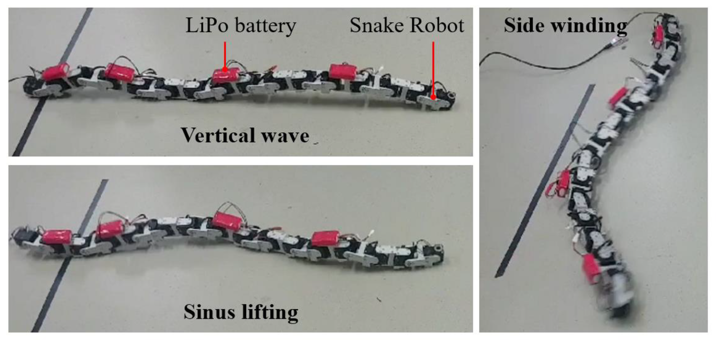
Snake robots should have various gait types to overcome rough terrain. In this section, we present the results of measurements on the locomotion performance when the snake robot conducted vertical motion, side winding motion, and sinus lifting motion on flatland. Each gait type of the snake robot is as shown in Figure 8.
The configuration for the experiment is as shown in Figure 9. The snake robot was controlled by a control PC, and a locomotion command was transmitted by a communication board (U2D2, Robotis). The distance from the start point to the end point was 1.5 m, and the time required for reaching the end point was measured, and the speed of each motion was measured. The locomotion speed when no DAM was attached and when the 12 cm DAM was attached were compared.

2.5. Friction Experiment of the DAM and the Frame

The experiment measured the friction coefficient of the DAM and the frame (materials: Aluminum 6061) that connects the servo motors of the snake robot because these friction properties may affect the locomotion performance. A y-stage that can move the object uniformly and a 1 kg load cell were used in the experiment. The y-stage that was attached to the load cell pushed the DAM and frame with 200 g weight. The friction coefficients of the DAM and the frame were obtained by the fundamental friction equation for the friction force, normal force, and external force that were caused by the y-stage. The experiment’s setup is shown in Figure 10.

2.6. Locomotion Experiment for Various Terrains

The environment used for testing locomotion performance on a slope is shown in Figure 11. The snake robot was placed on a 27 degree slope, and the slope was composed of grassland, which interrupted the locomotion of the snake robot. The purpose of this experiment was to confirm that the DAM works effectively to overcome the slope terrain without extra driving algorithms and sensors. For this purpose, we analyzed whether the snake robot rolls down when performing vertical motion, side winding motion, and sinus lifting motion on a slope.
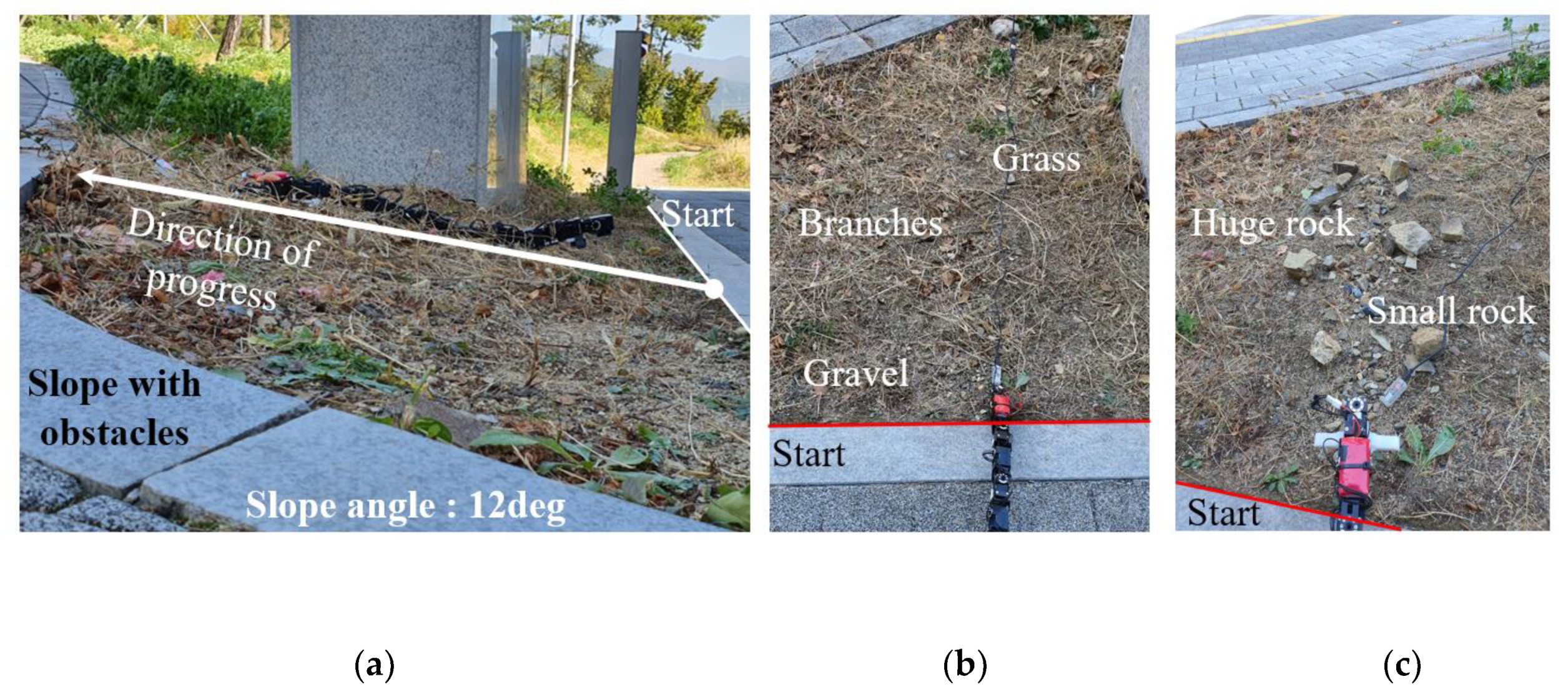
An experiment on a 12 degrees slope that had obstacles was conducted for verifying the ascending performance of the DAM, as shown in Figure 12a. There were two types of obstacles used for testing the role of the DAM. The first obstacles were gravel, branches, and grass, the second obstacles were a small rock and large rock, as shown in Figure 12b,c. In this experiment, the vertical motion was used because vertical motion is suitable for ascending a slope.
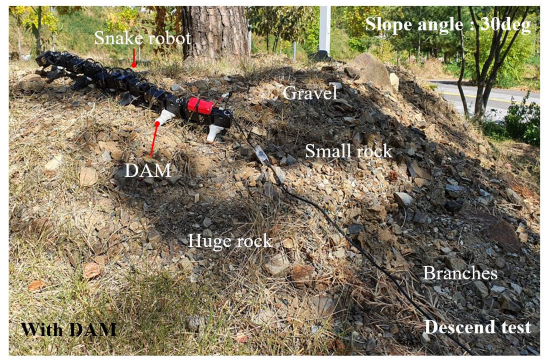
An experiment on a 30 degrees slope that had various obstacles was performed for verifying the descending performance of the DAM, as shown in Figure 13. There were various obstacles such as gravel, a small rock, a large rock, and branches with soil. In this experiment, the sinus lifting motion was used because it is a stable motion. In addition, the experiment on the surface that is composed of gravel was conducted for verifying the robustness of the performance of the DAM, as shown in Figure 14. In this experiment, both the vertical motion and sinus lifting motion were used for testing the locomotion performance.

3. Results

3.1. Experiment Results of Slope Condition

A graph comparing the theoretical values with experiment values is shown in Figure 15. The maximum error between the theoretical values and the experiment values was 49% when the DAM length was 12 cm, and the minimum error value was 25% when the DAM length was 18 cm. As the length of the DAM increased, the maximum slope angle increased. The theoretical values and the experiment values were compared using a trend line and the method of least squares. As a result of the least squares method, the gradient of the theoretical values’ trend line was 5.4, and the gradient of the experiment values’ trend line was 6.8. It can be confirmed that the error of the ratio of the maximum slope angle was 20.6%.
The value of the moment of inertia was measured using the I-property function of Autodesk inventor, and that may differ from the real value. The dynamic modeling did not consider the friction characteristics of the DAM and the surface. In addition, in the process of measuring the current or measuring Δt, the values of the sensor may have differed from the real values. These issues may have caused the error between the theoretical values and the experiment values. In the future, it is possible that the difference between the dynamic modeling and the experiment can be reduced by taking these factors into consideration.

3.2. Locomotion Experiment Results for Various Gait Types

The average value of three repetitions of the experiment results with and without the DAM are shown in Figure 16. When the DAM was not attached, the average value of the locomotion speed of the vertical motion was 4.44 cm/sec, the sinus lift motion was 4.14 cm/sec, and the sidewinding motion was 20.49 cm/sec. When a 12 cm DAM was attached to the snake robot, the average value of the locomotion speed of the vertical motion was measured at 6.34 cm/sec, the sinus lift motion was 8.01 cm/sec, and the side winding motion was 26.5 cm/s. As a result of attaching the DAM, the locomotion speed of the vertical motion increased by 29.96%, sinus lifting motion increased by 48.31%, and side winding motion increased by 22.6%. In this way, it was confirmed that the DAM plays a role not only in stable locomotion on a slope but also in increasing locomotion speed on flat terrain.

3.3. Friction Experiment of the DAM and the Frame

Each mean friction coefficients of the DAM and the frame were 0.050 and 0.044, respectively, as a result of the three repetitive experiments as shown in Figure 17. The difference between the two friction coefficients was 0.006, so we confirmed that the DAM did not change the friction property.

3.4. Locomotion Experiment Results on Various Terrains

When the DAM was not attached, the snake robot rolled down when performing the vertical motion, side winding motion, and sinus lifting motion due to unstable terrain. On the other hand, when the 12 cm DAM was attached, the snake robot conducted the same three locomotion types well in the same environment. The results are shown in Figure 18 and Figure 19. In the case of vertical motion, the robot was not rolled and was able to go down the slope as shown in Figure 18. Next, we confirmed that both side winding motion and sinus lifting motion did not roll down on the slope and went down stably.
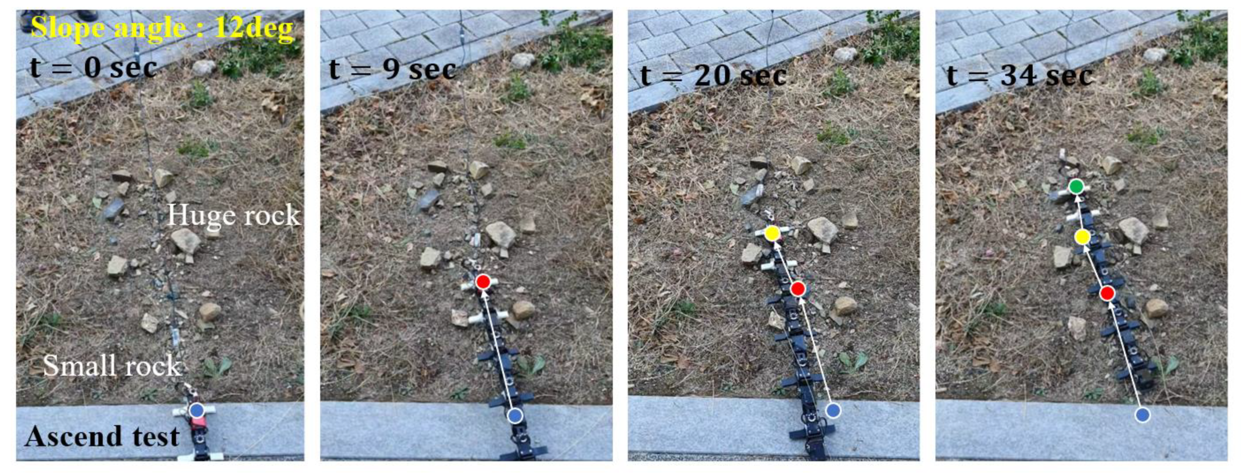
The experiment on the 12 degrees slope that had obstacles was conducted for verifying the ascending performance of the DAM. In the case of the snake robot without the DAM, the snake robot rolled down when it hit the obstacles, as shown in Figure 20. In the case of the snake robot with the DAM, the snake robot ascended the 12 degrees slope that had branches and gravel without rolling down, as shown in Figure 21. In addition, the snake robot ascended the 12 degrees slope that had rocks by pushing the rocks with the DAM, as shown in Figure 22.
The experiment on the 30 degrees slope that had various obstacles was performed to verify the descending performance of the DAM. In the case of the snake robot without the DAM, the snake robot rolled down when it hit the obstacles, as shown in Figure 23. In the case of the snake robot with the DAM, the snake robot descended the 30 degrees slope that had branches, gravel, and rocks without rolling down, as shown in Figure 24.
The experiment on the surface that was composed of gravel was conducted to verify the robust performance of the DAM. In the case of the snake robot without the DAM, the snake robot rolled down when it hit the gravel, as shown in Figure 25a,b, when the snake robot performed vertical motion and sinus lifting motion. With vertical motion of the snake robot with the DAM, the snake robot moved forward, but it got caught in the gravelly field, as shown in Figure 26a. In the sinus lifting motion of the snake robot with the DAM, the snake robot moved forward without catching in the gravelly field, as shown in Figure 26b, because the DAM pushed the gravel with the propulsion of the snake robot.

4. Discussion and Conclusions

In this paper, we showed that when the driving assistant mechanism (DAM) is attached to a snake robot, it can perform locomotion on rough terrain such as a slope or grasslands without additional driving algorithms and sensors. In the slope environment, vertical motion and side winding motion can be used in descending the slope and vertical motion can be used in ascending the slope. Sinus lifting motion can be used in transverse motion of a slope environment. However, it is impossible for the DAM alone to overcome all terrain. In other words, if the DAM, driving algorithm, and sensors are in harmony, higher slopes and rougher terrains can be overcome. In addition, the DAM can be studied in the future for various materials such as soft materials and shapes.
A dynamic analysis of a snake robot with a DAM for vertical motion was conducted in this paper. The results were compared with the experiment’s results in a slope condition. The maximum error between the theoretical values and the experiment values was 49% when the DAM length was 12 cm, and the minimum error value was 25% when the DAM length was 18 cm. In addition, it was confirmed that as the length of the DAM became longer, the maximum slope angle that the snake robot could overcome became larger from both the dynamic analysis and the experiment. When the length of DAM was 18 cm, it was confirmed that the snake robot did not roll down on a 42 degrees slope. However, if the length of the DAM becomes longer, the advantage of the snake robot being able to move through narrow terrain is reduced, and there is a possibility that the operation of the snake robot’s motor may be interrupted. Therefore, DAMs must be able to fold and unfold if they are going to be used in the field. In addition, it is expected that advanced dynamic modeling of the side winding motion and sinus lifting motion will help overcome rough terrain effectively.
In locomotion experiments, it was confirmed that the locomotion speed was increased by the DAM. The locomotion speed increased by 29.96%, 48.31%, and 22.6% in the vertical motion, sinus lifting motion, and side winding motion, respectively. We measured the friction coefficient to find out the reason for the improvement in the speed. However, there was not a distinct difference between DAM’s friction coefficient and the frame’s friction coefficient; the friction coefficients of the DAM and the frame were 0.050 and 0.044, respectively. The improvement in the speed may be caused by other changes of dynamic properties and the clear reason of the improvement can be researched in future work. Through experiments on rough terrain, such as on a slope and in a gravelly field, it was confirmed that the DAM improved the locomotion performance. The DAM prevented rolling of the snake robot down on the slope and generated propulsion by pushing on the obstacles with the DAM. In the slope environment, the vertical motion with the DAM is suitable for ascending slopes and the sinus lifting motion with the DAM is suitable for descending slope. One drawback that was found is that the DAM caught in obstacles, however, this can be overcome by the sinus lifting motion. In this experiment, we confirmed that the sinus lifting motion with the DAM has robustness in an environment that has obstacles.

Author Contributions

Conceptualization, J.B., M.K., B.S. and D.Y.; methodology, J.B. and M.K.; formal analysis, J.B.; investigation, J.B., M.J.; data curation, M.K.; writing—original draft preparation, J.B.; writing—review and editing, J.B., M.K., M.J., and D.Y.; visualization, J.B.; supervision, D.Y. and M.J.; project administration, D.Y.; funding acquisition, D.Y. and M.J.; All authors have read and agreed to the published version of the manuscript.

Funding

This material is based upon work supported by the Ministry of Trade, Industry and Energy (MOTIE, Korea) under Industrial Technology Innovation Program. No. 20003739.

Conflicts of Interest

The authors declare no conflict of interest.

References

  1. Sanfilippo, F.; Azpiazu, J.; Marafioti, G.; Transeth, A.A.; Stavdahl, Ø.; Liljebäck, P. Perception-driven obstacle-aided locomotion for snake robots: The state of the art, challenges and possibilities. Appl. Sci. 2017, 7, 336. [Google Scholar] [CrossRef]
  2. Yun, D. Development of a mobile robot mimicking the frilled lizard. J. Mech. Sci. Technol. 2018, 32, 1787–1792. [Google Scholar] [CrossRef]
  3. Ariizumi, R.; Matsuno, F. Dynamic analysis of three snake robot gaits. IEEE Trans. Robot. 2017, 33, 1075–1087. [Google Scholar] [CrossRef]
  4. Liljeback, P.; Pettersen, K.Y.; Stavdahl, Ø.; Gravdahl, J.T. Controllability and stability analysis of planar snake robot locomotion. IEEE Trans. Autom. Control 2010, 56, 1365–1380. [Google Scholar] [CrossRef] [Green Version]
  5. Takemori, T.; Tanaka, M.; Matsuno, F. Gait design for a snake robot by connecting curve segments and experimental demonstration. IEEE Trans. Robot. 2018, 34, 1384–1391. [Google Scholar] [CrossRef]
  6. Wang, X.; Zhang, Q.; Shen, D.; Chen, J. A Novel Rescue Robot: Hybrid Soft and Rigid Structures for Narrow Space Searching. In Proceedings of the 2019 IEEE International Conference on Robotics and Biomimetics (ROBIO), Dali, Yunnan, China, 6–8 December 2019; pp. 2207–2213. [Google Scholar]
  7. Manzoor, S.; Khan, U.; Ullah, I. Serpentine and Rectilinear Motion Generation in Snake Robot Using Central Pattern Generator with Gait Transition. Iran. J. Sci. Technol. Trans. Electr. Eng. 2019, 44, 1–11. [Google Scholar] [CrossRef]
  8. Huq, N.M.L.; Khan, M.R.; Shafie, A.A.; Billah, M.M.; Ahmmad, S.M. Motion Investigation of a Snake Robot with Different Scale Geometry and Coefficient of Friction. Robotics 2018, 7, 18. [Google Scholar] [CrossRef] [Green Version]
  9. Liljebäck, P.; Pettersen, K.Y.; Stavdahl, Ø.; Gravdahl, J.T. A review on modelling, implementation, and control of snake robots. Robot. Auton. Syst. 2012, 60, 29–40. [Google Scholar] [CrossRef] [Green Version]
  10. Selvarajan, A.; Kumar, A.; Sethu, D.; bin Ramlan, M.A. Design and Development of a Snake-Robot for Pipeline Inspection. In Proceedings of the 2019 IEEE Student Conference on Research and Development (SCOReD), Bandar Seri Iskandar, Malaysia, 15–17 October 2019; pp. 237–242. [Google Scholar]
  11. Whitman, J.; Zevallos, N.; Travers, M.; Choset, H. Snake robot urban search after the 2017 Mexico City earthquake. In Proceedings of the 2018 IEEE international symposium on safety, security, and rescue robotics (SSRR), Philadelphia, PA, USA, 6–8 August 2018; pp. 1–6. [Google Scholar]
  12. Chang, A.H.; Vela, P.A. Shape-centric modeling for control of traveling wave rectilinear locomotion on snake-like robots. Robot. Auton. Syst. 2020, 124, 103406. [Google Scholar] [CrossRef]
  13. Manzoor, S.; Cho, Y.G.; Choi, Y. Neural oscillator based CPG for various rhythmic motions of modular snake robot with active joints. J. Intell. Robot. Syst. 2019, 94, 641–654. [Google Scholar] [CrossRef]
  14. Yun, D.; Fearing, R.S. Cockroach Milli-Robot With Improved Load Capacity. J. Mech. Robot. 2019, 11, 1. [Google Scholar] [CrossRef]
  15. Yun, D.; Kim, K.-S.; Kim, S.; Kyung, J.; Lee, S. Note: Dynamic analysis of a robotic fish motion with a caudal fin with vertical phase differences. Rev. Sci. Instrum. 2013, 84, 036108. [Google Scholar] [CrossRef] [PubMed] [Green Version]
  16. Gong, C.; Tesch, M.; Rollinson, D.; Choset, H. Snakes on an inclined plane: Learning an adaptive sidewinding motion for changing slopes. In Proceedings of the 2014 IEEE/RSJ International Conference on Intelligent Robots and Systems, Chicago, IL, USA, 14–18 September 2014; pp. 1114–1119. [Google Scholar]
  17. Koopaee, M.J.; Bal, S.; Pretty, C.; Chen, X. Design and Development of a Wheel-less Snake Robot with Active Stiffness Control for Adaptive Pedal Wave Locomotion. J. Bionic Eng. 2019, 16, 593–607. [Google Scholar] [CrossRef]
  18. Sanfilippo, F.; Helgerud, E.; Stadheim, P.A.; Aronsen, S.L. Serpens, a low-cost snake robot with series elastic torque-controlled actuators and a screw-less assembly mechanism. In Proceedings of the 2019 5th International Conference on Control, Automation and Robotics (ICCAR), Beijing, China, 19–22 April 2019; pp. 133–139. [Google Scholar]
  19. Transeth, A.A.; Leine, R.I.; Glocker, C.; Pettersen, K.Y.; Liljebäck, P. Snake robot obstacle-aided locomotion: Modeling, simulations, and experiments. IEEE Trans. Robot. 2008, 24, 88–104. [Google Scholar] [CrossRef] [Green Version]
  20. Fjerdingen, S.A.; Liljebäck, P.; Transeth, A.A. A snake-like robot for internal inspection of complex pipe structures (PIKo). In Proceedings of the 2009 IEEE/RSJ International Conference on Intelligent Robots and Systems, St. Louis, MO, USA, 10–15 October 2009; pp. 5665–5671. [Google Scholar]
  21. Mori, M.; Hirose, S. Three-dimensional serpentine motion and lateral rolling by active cord mechanism ACM-R3. In Proceedings of the IEEE/RSJ International Conference on Intelligent Robots and Systems, Lausanne, Switzerland, 30 September–4 October 2002; pp. 829–834. [Google Scholar]
  22. McKenna, J.C.; Anhalt, D.J.; Bronson, F.M.; Brown, H.B.; Schwerin, M.; Shammas, E.; Choset, H. Toroidal skin drive for snake robot locomotion. In Proceedings of the 2008 IEEE International Conference on Robotics and Automation, Pasadena, CA, USA, 19–23 May 2008; pp. 1150–1155. [Google Scholar]
  23. Ma, S.; Tadokoro, N. Analysis of creeping locomotion of a snake-like robot on a slope. Auton. Robot. 2006, 20, 15–23. [Google Scholar] [CrossRef] [Green Version]
  24. Bing, Z.; Cheng, L.; Knoll, A.; Zhong, A.; Huang, K.; Zhang, F. Slope angle estimation based on multi-sensor fusion for a snake-like robot. In Proceedings of the 2017 20th International Conference on Information Fusion (Fusion), Xi’an, China, 10–13 July 2017; pp. 1–6. [Google Scholar]
  25. Li, D.; Wang, C.; Deng, H.; Wei, Y. Motion Planning Algorithm of a Multi-Joint Snake-Like Robot Based on Improved Serpenoid Curve. IEEE Access 2020, 8, 8346–8360. [Google Scholar] [CrossRef]
Figure 1. Conceptual diagram for locomotion of a snake robot (a) without a driving assistant mechanism (DAM) and (b) with a DAM.
Applsci 10 07478 g001
Figure 2. Modeling of a snake robot with a DAM. (a) Snake robot with a DAM. (b) Design of the DAM.
Applsci 10 07478 g002
Figure 3. Analysis models of the DAM using a finite element analysis (FEA). (a) Stress analytical result. (b) Displacement analytical result.
Applsci 10 07478 g003
Figure 4. Configuration for dynamic modeling of the snake robot with a DAM.
Applsci 10 07478 g004
Figure 5. Free body diagram of the dynamic modeling. (a) The force which acted on DAM and slope. (b) Freebody diagram when the DAM lifted. (c) The moment when the center of mass located on the z-axis.
Applsci 10 07478 g005
Figure 6. Graph of the current with various lengths of DAMs.
Applsci 10 07478 g006
Figure 7. Experiment configuration for verifying dynamic modeling.
Applsci 10 07478 g007
Figure 8. The snake robot’s gait types on flatland.
Applsci 10 07478 g008
Figure 9. Configuration for flatland experiment.
Applsci 10 07478 g009
Figure 10. Experiment setup for measuring the friction coefficient.
Applsci 10 07478 g010
Figure 11. Experiment environment in rough terrain.
Applsci 10 07478 g011
Figure 12. Ascending environments composed of obstacles. (a) 12 Degree slope environments. (b) The experiments environments which have the grass, branches and gravel. (c) The experiments environments which have the small and huge rock.
Applsci 10 07478 g012
Figure 13. Descending environment composed of obstacles.
Applsci 10 07478 g013
Figure 14. Gravelly field for testing the robustness of the performance of the DAM.
Applsci 10 07478 g014
Figure 15. Dynamic modeling values and experiment values in the slope condition.
Applsci 10 07478 g015
Figure 16. Locomotion speed for three movement types when the DAM was attached and when the DAM was not attached.
Applsci 10 07478 g016
Figure 17. Friction coefficient result.
Applsci 10 07478 g017
Figure 18. Performance of vertical motion with the DAM in rough terrain.
Applsci 10 07478 g018
Figure 19. Performance of side winding and sinus lifting motion with the DAM in rough terrain.
Applsci 10 07478 g019
Figure 20. Performance of the ascending motion without the DAM.
Applsci 10 07478 g020
Figure 21. Performance of the ascending motion with the DAM in the branches and gravel environment.
Applsci 10 07478 g021
Figure 22. Performance of the ascending motion with the DAM on the rocks.
Applsci 10 07478 g022
Figure 23. Performance of the descending motion without the DAM on the slope.
Applsci 10 07478 g023
Figure 24. Performance of the descending motion with the DAM on the slope.
Applsci 10 07478 g024
Figure 25. Performance of the robustness without the DAM on the gravelly field. (a) The vertical motion with DAM in the gravelly field. (b) The sinus lifting motion with DAM in the gravelly field.
Applsci 10 07478 g025
Figure 26. Performance of the robustness with the DAM on the gravelly field. (a) The vertical motion with DAM in the gravelly field. (b) The sinus lifting motion with DAM in the gravelly field.
Applsci 10 07478 g026
Table 1. Parameters for dynamic modeling.
SymbolDescriptionValueUnit
LLength of the DAM
(Length of the Servo Motor)
0.09, 0.12, 0.15, 0.18
(0.045)
m
LcmY coordinate of the one module’s center of mass 0.034m
L1Distance between rotational axis and gravity force-m
L2Distance between rotational axis and action force-m
L3Distance between rotational axis and gravity force-m
θ1Degree of the inclined plane-rad
mMass of the one module of the snake robot0.175kg
IMoment of inertia without DAM
(with DAM)
0.00097 (0.0012)kg·m2
KTMotor torque constant1.23A/N·m
i0No load current0.07A
gAcceleration of gravity 9.81m/s2
Fm2Magnitude of substitution force of F m -N
Fm3Magnitude of reaction force of F m 2 -N
Publisher’s Note: MDPI stays neutral with regard to jurisdictional claims in published maps and institutional affiliations.