Numerical Analysis of the Bottom Thickness of Closed Rectangular Tanks Used as Pontoons


Department of Construction and Geoengineering, Faculty of Environmental and Mechanical Engineering, Poznan University of Life Sciences, Piatkowska Street 94, 60-649 Poznan, Poland
Appl. Sci. 2020, 10(22), 8082; https://doi.org/10.3390/app10228082
Submission received: 13 October 2020
/
Revised: 30 October 2020
/
Accepted: 11 November 2020
/
Published: 15 November 2020
(This article belongs to the Section Civil Engineering)
Abstract
:This paper concerns the numerical analysis of closed rectangular tanks made in one stage, used as pontoons. Such structures can be successfully used as floating platforms, although they primarily serve as floats for ‘houses on water’. Amphibious construction has fascinated designers for many years and is becoming, in addition to a great and prestigious location for many purposes, a practical global necessity. Severe weather phenomena that no country is safe from, i.e., heavy rains or floods, combined with the scarcity of space intended for the construction of residential buildings, encourage development at the contact of water and land or on water only. This paper contains an analysis of the static work of tanks with different bottom thickness subjected to hydrostatic load acting on tank walls and the bottom plate and evenly distributed load acting on the upper plate, i.e., major impacts that occur when tanks are used as pontoons. Calculations were made using the finite difference method in terms of energy, assuming the Poisson’s ratio ν = 0. Based on the solutions obtained, charts were made that illustrated the change in bending moments at the characteristic points of the analysed tanks depending on acting loads. The article also includes calculations of buoyancy, stability and the metacentric height for tanks with different bottom thicknesses, with the main purpose being to improve and share knowledge on their safe use as pontoons.
1. Introduction
Tanks as civil engineering structures have been used in numerous branches of industry and the economy for many years. Applications of tanks as civil engineering structures include swimming pools, fire tanks, clean water tanks, waste tanks and tanks for fuel rectification products. As there are many applications of these types of structures, the analysis of their static work is important [1]. The most frequently designed and produced tanks have a constant wall thickness, regardless of whether their cross-sections are rectangular or circular. If they are closed tanks, the cover is usually a plate based freely on the walls, whereas the bottom is a bottom plate that is usually thicker than the tank walls. The contact between the bottom plate and tank walls is assumed to be rigid in static analysis. Tanks with walls of variable thickness (i.e., of trapezoidal cross-section) are very rarely designed despite their optimal adjustment to stress distribution (from the point of view of calculation schemes). For tanks hydrostatically loaded, the load acting on walls increases with the depth (of foundations), and triangular load distribution means that the highest values of bending moments in the vertical cross-section occur at the point where the wall connects to the bottom, while the upper free edge of the tank has a zero value. Thus, structural and economic considerations should determine the selection of walls with a thickness that increases accordingly with the immersion of the tank [2,3]. Changes in internal forces occurring along the longer wall of the tank also apply to bridge structures, where the interaction between incoherent backfill (similar to a fluid) and spandrel walls is studied [4,5].
Floats used for constructing floating platforms can be made of plastic, steel or aluminium sheets, as well as reinforced concrete. These structures often consist of two elements: a box and a cover plate. As a result, they can be treated computationally as rectangular open tanks with the upper plate resting freely on walls. The solution carries either the risk of inaccuracy in assembly or possible leaks and faster wear in use [6]. A better proposal, although it is more difficult in terms of calculation and performance, is to design and construct a monolithic reinforced concrete tank concreted entirely in one stage [7]. The structure is then computationally treated as a closed rectangular tank. Reinforced concrete pontoons intended for the construction of floating platforms should have adequate buoyancy and be stable; i.e., they should not show excessive tilt at partial load [6,8].
Stationary floating structures are becoming increasingly popular around the world, stimulated by various reasons [9]. It is estimated that there are 40,000 to 50,000 such structures [10]. They are considered to be architecturally attractive with pleasing locations. On the other hand, their construction is associated with changes in water levels [11] or with high population density, and they are seen as a way of ensuring enough living space for people. Severe and rapid meteorological phenomena such as typhoons, hurricanes and floods affect many areas of the world. Climatologists predict that water levels will have risen by a meter by the end of the century. Amphibious construction is one of the building solutions oriented towards the urbanisation of floodplains. However, it is necessary to recognise the statics of their construction so that ‘houses on water’ can become a viable alternative to traditional construction [12].
The purpose of this article is to analyse the statics of closed rectangular tanks, the distribution of internal forces and the impact of bottom thickness on the values of occurring bending moments, the buoyancy and the stability of the pontoon. The subject matter of plate structures is well known in engineering literature. As for the design of tanks, scientific publications most often refer to open tanks, in which calculations are made using the finite element method. There are few works on closed rectangular tanks, and additionally, this paper includes calculations with the finite difference method, which is used even less frequently than the finite element method. The work is of an applied nature and contributes to the considerations on the construction of closed rectangular tanks and their use as pontoons. It also shows the possibility of applying the finite difference method to calculate a structure as an alternative to or verification of the finite element method.
2. Materials and Methods
2.1. Calculation Method
Monolithic rectangular tanks are complex plate structures characterised by spatial static work, so the load acting on one fragment of the structure causes displacement and creates cross-sectional forces throughout the system. Failure to consider it in the static calculations leads to incorrect determination of internal forces (bending moments and cutting forces), which in turn affects the value and distribution pattern of the adopted reinforcement and the correct design of the structure.
One of the numerical methods that can be successfully used in calculating these structures is the finite difference method in a variational approach. It takes into account the spatial work of structures, the real geometric dimensions (E and ν) corresponding to the material from which the tank will be made and any type of acting load, including temperature load. Apart from the finite element method, the finite difference method is one of the most popular numerical methods used for static calculations of building structures. The subject matter has been taken up in numerous outstanding and fundamental scientific works [13,14,15,16,17,18,19,20,21,22,23,24,25,26]. The method has been used in calculations regarding plate structures [3,27,28], tanks [2,7] or surface girders. The finite difference method (FDM) is one of the methods used to solve differential equations that are difficult or impossible to solve analytically. It is based on the energy functional accumulated in the deformed system. The finite difference method adopted for the numerical analysis was validated in [2]. The verification process of this method consisted in calculating the deflections of the tank using the traditional approach, i.e., the solution of the matrix of the displacement equation system using the finite difference method and the calculation of the tank with a specialised computer program based on the finite element method and on measurements of actual deflections using a coordinate measuring arm with a contact head [2]. The results found the finite difference method was suitable for solving the given analytical problems.
The solutions presented in the paper were obtained using the energy functional presented in the formula below (1) [23].
where D = is plate flexural rigidity, E is elasticity modulus of material, v is Poisson’s ratio, h is plate thickness, w is plate deflection, q is load perpendicular to the central surface of the plate, A is plate area, ΔT is difference in temperature between lower plate Td and upper plate Tg determined by correlation: ΔT = Td − Tg, αt is coefficient of thermal expansion of the plate material and K is subgrade stiffness reaction.
Further analysis was based on the adopted denominations (2):
On the assumption that the Poisson’s ratio was v = 0, and excluding the parameter of temperature, the energy functional changed its form into Formula (3) [23].
2.2. Verification of Pontoon Buoyancy and Stability
Rectangular tanks used as pontoons in the construction of floating platforms, besides the appropriate strength of their walls, must meet the requirements of buoyancy and stability. Pontoon buoyancy is determined by calculating its immersion depth and by controlling its freeboard, i.e., the vertical distance from the top edge of the pontoon (deck) to the surface of the water. Pontoon stability is determined by the location of the metacentric point and the tilt angle of the pontoon. The metacentre is the theoretical intersection point of the buoyant vector of the tilted floating vessel and its plane of symmetry. The distance from the centre of gravity of the floating vessel (e.g., pontoon), the metacentric height, is a measure of its stability [6]. In floating vessels, gravity and buoyancy forces are applied to different points. When the floating vessel is not tilted, both forces are in one straight line, perpendicular to the level of water. When the floating vessel tilts due to acting loads, the point at which the buoyancy force is applied is shifted in the direction to which the tilt occurs. A vertical line that is perpendicular to the water level and passes through the buoyancy force application point at the point of intersection with the axis of symmetry of the floating vessel marks the point known as the metacentre.
If the metacentre is above the centre of gravity, i.e., the metacentric height is positive, then the balance of the floating vessel is stable. If the metacentric distance is negative, it indicates unstable equilibrium.
According to recommendations adopted in Poland, in compliance with [29] when designing platforms to be loaded with a crowd, it should be assumed that the load is 3.0 kPa, and the tilt should be verified by acting on half the platform width with a load of 1.0 kPa. The freeboard of floating elements should be at least 0.05 m, with the tilt angle not exceeding 6° (according to [8]) and 10° (according to [29]). Simplified calculations can be performed in compliance with [30] for the tilt angle not exceeding 15°. When verifying stability, buoyancy and metacentric height, characteristic loads should be included in calculations (i.e., load factor γF = 1) by analogy with the verification of serviceability limit states provided in, for instance, Eurocode 2 [31]. PN-EN 14504 [8] states that when verifying the stability of floating platforms, the partial safety factor should be taken as equal to 1.0. The results of stability and metacentric height calculations presented later in this paper were obtained on the basis of the procedures provided for in the Australian Standard AS 3962-2001 [30]. Figure 1a shows the schematic drawing of the pontoon (cross-section) used to verify buoyancy, and Figure 1b shown the schematic used to verify stability.
3. Results
3.1. Static Analysis of the Tanks
By using the finite difference method in a variational approach, static calculations were made for five closed monolithic rectangular tanks with axial dimensions lx:ly:lz = 4:1:0.5, assuming in each case thicker bottom plates compared to the thickness of tank walls. The bottom thickness of the pontoon was determined as h, and the calculated bottom thickness values for individual tanks were 1 h, 1.25 h, 1.5 h, 1.75 h and 2.0 h. The division grid was adopted with square cell shape, with the mesh size equal to ly/12. With this division grid, by taking into account the plane of symmetry, a system of equations with 823 unknowns was obtained for each half of the tank. The following loads were assumed: hydrostatic load acting on tank walls, uniform load acting on the bottom (Figure 2a) and uniform load acting on the upper plate of the tank (Figure 2b).
Table 1 and Table 2 summarise coefficients proportional to deflections and coefficients proportional to bending moments for selected characteristic points of the tanks shown in Figure 3. To calculate definite values of bending moments and deflections, the β and β1 coefficients provided in Table 1 and Table 2 should be multiplied by 10−2qi ly2 for bending moments and 10−4qi ly4/D for deflections, where D = Eh3/12 [32,33].
Figure 4 and Figure 5 graphically show the changes in bending moments for the calculated tanks depending on bottom thickness values.
In order to analyse the effect of the bottom thickness on the change in deflections and bending moments, charts were produced that show the distribution of these values in the cross-sections running in the middle of the analysed tanks. The charts are shown in Figure 6, Figure 7, Figure 8 and Figure 9.
Figure 6 shows the distribution of deflections in the cross-section of the tank at half of its length from the acting hydrostatic load. This load causes the greatest deflections in the bottom plate. As the thickness of the bottom plate increases, the deflection in the bottom decreases, and deflections in the upper plate and tank walls also decrease.
Figure 7 shows the distribution of bending moments in the cross-section of the tank at half of its length from the acting hydrostatic load. This load causes the greatest bending moments in the bottom plate. As the thickness of the bottom plate increases, the value of the bending moment in the bottom in the middle of the tank width increases, while clamping moments decrease. The values of bending moments in the upper plate and tank walls also decrease.
Figure 8 shows the distribution of deflections in the cross-section of the tank at half its length from the evenly distributed load acting on the upper plate. This load causes the greatest values of deflections in the upper plate. As the thickness of the bottom plate increases, the deflection in the bottom decreases, and the deflections in the upper plate and tank walls also decrease.
Figure 9 shows the distribution of bending moments in the cross-section at half of its length from the evenly distributed load acting on the upper plate. This load causes the greatest bending moments in the upper plate. As the thickness of the bottom plate increases, the value of bending moment in the bottom, both in the middle of its width and the clamping moment, increases. On the other hand, the values of clamping moments in the upper plate and tank walls increase, and the values of bending moments in the middle of the width of the tank decrease.
3.2. Calculation Results of Buoyancy and Stability
Following the recommendations of Australian standard AS 3962-2001 [31] and using the dependencies detailed and described in the paper [32,33,34], buoyancy at self-load and at service load evenly distributed on the upper plate, amounting to 3.0 kN/m2, was calculated for the analysed tanks differing in bottom thickness. Moreover, the metacentric height and tilt angle were calculated with half of the upper plate loaded 1.0 kN/m2.
The following data was used for detailed calculations: length lx = 10 m, width ly = 2.5 m, height lz = 1.25 m, thickness of tank walls and the upper plate h = 0.08 m, reinforced concrete class C35/45, Styrofoam filling with a volumetric weight 0.45 kN/m3.
The results of the calculations are summarised in Table 3.
4. Discussion
This paper presents calculation results for closed monolithic rectangular tanks performed in one stage and analyses the impact of bottom plate thickness on the distribution and values of deflections and bending moments in the considered system. No relevant results have been found in the literature for this type of structure.
Since there are still problems related to the analysis, design and execution of concrete floating structures, the matter is considered to be challenging [35]. Most of the available and constructed reinforced concrete floats consist of a box and a covering plate. However, this approach is uncertain, since each contact can be a potential spot through which water gets inside [36]. The closed rectangular tank analysed in the paper is an effective solution that eliminates the possibility of water getting inside the structure [7,34]. Tight filling of the box with polystyrene means water that could possibly get inside has no place to accumulate.
By taking into account in static calculation the interaction of the tank structures with Styrofoam filling treated as an elastic foundation, all points of the structure see the reduction in the values of bending moments, sometimes even by approximately 30–40%. Including the Poisson’s ratio ν ≠ 0 in calculations results in obtaining, for the central parts of plates (beyond the edges of the tank), the values of bending moments higher than calculated for ν = 0. Including the Poisson’s ratio in static calculation in closed monolithic tanks does not affect the values of bending moments occurring on the edges. Parameters such as ν and K do not affect the calculation related to the so-called freeboard [33].
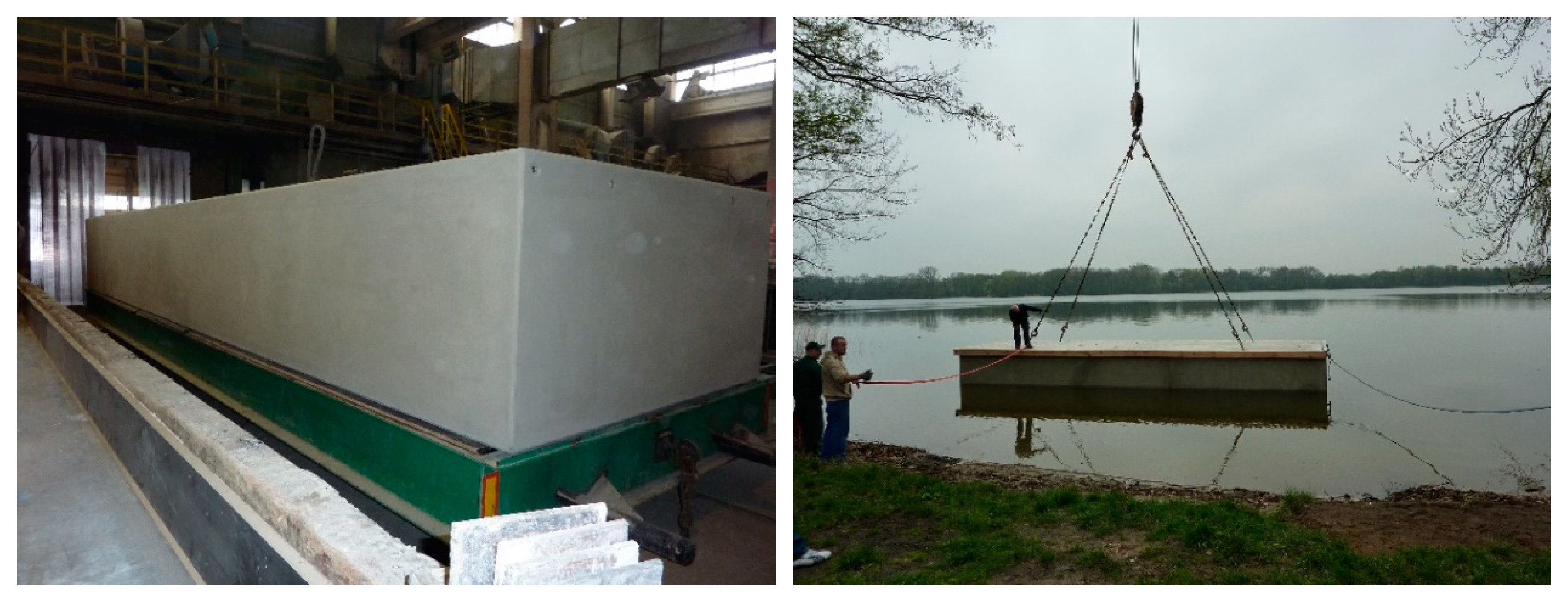
Pontoons are structures exposed to numerous actions that are often difficult to define. That is why the tests that are carried out on life-size structures and in the form of case studies [7,34,37] are even more valuable. Publications [7,34] include calculations of a unique reinforced concrete closed rectangular tank, which was made in the form of a life-size model and subjected to testing. The tank has walls of a constant thickness and a diaphragm in the middle of its length. Therefore, scientific considerations based on the finite difference method are subject to model verification. Figure 10 shows a prototype closed rectangular tank in the construction phase and during launching.
5. Conclusions
The calculation results presented in this paper were obtained using the finite difference method in terms of energy, taking into account spatial static work.
By analysing the presented solutions, the following findings were obtained:
- Thickening of the bottom plate in relation to the constant and identical wall and upper plate thickness, at all points of the calculated tanks, led to a reduction in deflections as the bottom thickness increased.
- Hydrostatic load on tank walls and uniform load on the bottom combined with an increase in the bottom thickness led to an increase in bending moments acting in the middle of the bottom plate span towards a shorter span (My2, Figure 3), while reducing bending moments at other points of the tank.
- Uniform load on the upper plate in tanks with a thicker bottom led to an increase in bending moments, but only in the bottom, both in fastening moments (MA2 and MB2, Figure 3) and in the moment acting in the centre of the plate towards a shorter span (My2, Figure 3). Bending moments at other points of the tank practically did not change.
- An increase in the thickness of the bottom plate leads to a change in the size of the pontoon’s tilt angle, which enables it to change easily, to smaller than required by applicable regulations (in this case φ ≤ 6°).
Funding
This research received no external funding.
Acknowledgments
The publication was co-financed within the framework of Ministry of Science and Higher Education programme as „Regional Initiative Excellence” in years 2019–2022, Project No. 005/RID/2018/19.
Conflicts of Interest
The author declares no conflict of interest.
References
- Halicka, A.; Franczak, D. Design of Reinforced Concrete Tanks. Volume 2. Tanks for Liquids; Wydawnictwo Naukowe PWN: Warsaw, Poland, 2014. [Google Scholar]
- Buczkowski, W.; Szymczak-Graczyk, A.; Walczak, Z. Experimental validation of numerical static calculations for a monolithic rectangular tank with walls of trapezoidal cross-section. Bull. Pol. Acad. Sci. Tech. Sci. 2017, 65, 799–804. [Google Scholar] [CrossRef] [Green Version]
- Szymczak-Graczyk, A. Rectangular plates of a trapezoidal cross-section subjected to thermal load. IOP Conf. Ser. Mater. Sci. Eng. 2019, 603, 032095. [Google Scholar] [CrossRef]
- D’Amato, M.; Laterza, M.; Casamassima, V.M. Seismic Performance Evaluation of Multi-Span Existing Masonry Arch Bridge. Open Civ. Eng. J. 2017, 11 (Suppl. 5), 1191–1207. [Google Scholar] [CrossRef]
- Pelà, L.; Aprile, A.; Benedetti, A. Seismic Assessment of masonry arch bridges. Eng. Struct. 2009, 31, 1777–1788. [Google Scholar] [CrossRef]
- Mazurkiewicz, B. Yacht Ports and Marinas. Design; Fundacja Promocji Przemysłu Okrętowego i Gospodarki Morskiej: Gdańsk, Poland, 2010. [Google Scholar]
- Szymczak-Graczyk, A. Floating platforms made of monolithic closed rectangular tanks. Bull. Pol. Acad. Sci. Tech. Sci. 2018, 66, 209–219. [Google Scholar] [CrossRef]
- PN–EN 14504:2010: Inland Waterway Vessels. Floating Harbors. Requirements, Tests; Polish Standardization Committee: Warsaw, Poland, 2010.
- Wang, C.M. Great, Ideas Float on the Top. In Large Floating Structures: Technological Advances; Wang, C.M., Wang, B.T., Eds.; Springer: Berlin/Heidelberg, Germany, 2015; pp. 1–36. [Google Scholar]
- Holcombe, S. Applications and Huge Potential Demand for Amphibious Structures. In Proceedings of the First International Conference on Amphibious Architecture, Design & Engineering, Waterloo, ON, Canada, 25–28 June 2017; Volume 138. [Google Scholar]
- Nakajima, T.; Umeyama, M. A New Concept for the Safety of Low-lying Land Areas from Natural Disasters. J. Ocean Eng. Mar. Energy 2015, 1, 19–29. [Google Scholar] [CrossRef] [Green Version]
- Ostrowska-Wawryniuk, K.; Piątek, Ł. Lightweight Prefabricated Floating Buildings for Shallow Inland Waters. Design and Construction of The Floating Hotel Apartment in Poland. J. Water Land Dev. 2020, 44, 118–125. [Google Scholar] [CrossRef]
- Gołaś, J. Introduction to the Theory of Plates; Opole University of Technology Publishing House: Opole, Poland, 1972. [Google Scholar]
- Donnell, L.H. Beams, Plates and Shells; McGraw-Hill: New York, NY, USA, 1976. [Google Scholar]
- Naghdi, P.M. The Theory of Shells and Plates; Handbuch der Physick: Berlin, Germany, 1972. [Google Scholar]
- Panc, V. Theries of Elastic Plates; Academia: Prague, Czech Republic, 1975. [Google Scholar]
- Timoshenko, S.; Woinowsky-Krieger, S. Theory of Plates and Coatings; Arkady: Warszawa, Poland, 1962. [Google Scholar]
- Szlilard, R. Theory and Analysis of Plates. Classical and Numerical Methods; Prentice Hall, Englewood Cliffs: Bergen, NJ, USA; Prentice-Hall: Upper Saddle River, NJ, USA, 1974. [Google Scholar]
- Ugural, A.C. Stresses in Plates and Shells; McGraw-Hill: New York, NY, USA, 1981. [Google Scholar]
- Wilde, P. Variational approach of finite differences in the theory of plate. In Proceedings of the Materials of XII Scientific Conference of the Committee of Science PZiTB and the Committee of Civil Engineering of Polish Academy of Sciences, Krynica, Poland, 12–17 September 1966. [Google Scholar]
- Tribiłło, R. Application of the generalized finite difference method for plate calculations. Arch. Inżynierii Lądowej 1975, 2, 579–586. [Google Scholar]
- Son, M.; Sang Jung, H.; Hee Yoon, H.; Sung, D.; Suck Kim, J. Numerical Study on Scale Effect of Repetitive Plate-Loading Test. Appl. Sci. 2019, 9, 4442. [Google Scholar] [CrossRef] [Green Version]
- Kączkowski, Z. Plates. Static Calculations; Arkady: Warszawa, Poland, 2000. [Google Scholar]
- Rapp, B.E. Chapter 30—Finite Difference Method. In Microfluidics: Modelling, Mechanics and Mathematics, Micro and Nano Technologies; Rapp, B.E., Ed.; Elsevier: Amsterdam, The Netherlands, 2017; pp. 623–631. [Google Scholar] [CrossRef]
- Blazek, J. Chapter 3—Principles of Solution of the Governing Equations. In Computational Fluid Dynamics: Principles and Applications; Blazek, J., Ed.; Elsevier: Amsterdam, The Netherlands, 2015; pp. 29–72. [Google Scholar] [CrossRef]
- Sadd, M.H. Chapter 5—Formulation and Solution Strategies. In Elasticity, Theory, Applications, and Numerics; Sadd, M.H., Ed.; Academic Press, Elsevier: Cambridge, MA, USA, 2005; pp. 83–102. [Google Scholar] [CrossRef]
- Szymczak-Graczyk, A. Numerical analysis of the impact of thermal spray insulation solutions on floor loading. Appl. Sci. 2020, 10, 1016. [Google Scholar] [CrossRef] [Green Version]
- Numayr, K.S.; Haddad, R.H.; Haddad, M.A. Free vibration of composite plates using the finite difference method. Thin-Walled Struct. 2004, 42, 399–414. [Google Scholar] [CrossRef]
- Z44, Recommendations for the Design of Offshore Hydrotechnical Structures, Z1–Z46; No. 21; Gdańsk University of Technology, Department of Maritime Construction. Studies and Materials: Gdańsk, Poland, 1997.
- AS 3962-2001: The Australian Standard: Guidelines for Design of Marinas; Standards Australia International Ltd.: Sydney, Australian, 2001.
- PN-EN 1992-1-1:2008 Eurocode 2. Design of Concrete Structures. Part 1-1. General Rules and Rules for Buildings; Polish Standardization Committee: Warsaw, Poland, 2008.
- Buczkowski, W.; Szymczak-Graczyk, A. The influence of the thickness of the bottom of the work and static stability of the pontoon made as a monolithic closed, reinforced concrete tank. In Modelling of structures and Engineering Structures; SGGW: Warsaw, Poland, 2014. [Google Scholar]
- Buczkowski, W.; Szymczak-Graczyk, A.; Walczak, Z. The analysis of static works of closed monolithic rectangular tanks. In Proceedings of the IV International Scientific Conference, Durability of Construction Work—Science and Research, Poznań, Poland, 19–21 November 2014. [Google Scholar]
- Szymczak-Graczyk, A. Floating Platforms Made from Monolithic, Closed Rectangular Tanks. Ph.D. Thesis, SGGW, Warsaw, Poland, 2014. [Google Scholar]
- Jiang, D.; Tan, K.H.; Wang, C.M.; Ong, K.C.G.; Bra, H.; Jin, J.; Kim, M.O. Analysis and design of floating prestressed concrete structures in shallow waters. Mar. Struct. 2018, 59, 301–320. [Google Scholar] [CrossRef]
- Spychalski, K.; Szymczak-Graczyk, A. Multi-criteria analysis of the selection of structural types of floating platforms. Mater. Bud. 2020, 2, 2–4. [Google Scholar] [CrossRef]
- Seifa, M.S.; Inoue, Y. Dynamic analysis of floating bridges. Mar. Struct. 1998, 11, 29–46. [Google Scholar] [CrossRef]
- Laks, I.; Walczak, Z. Modelling of the impact of the retention reservoir on the flood protection of the city—A case study for the city of Kalisz (Central Poland). IOP Conf. Ser. Mater. Sci. Eng. 2019, 603, 022066. [Google Scholar] [CrossRef] [Green Version]
- Laks, I.; Walczak, Z.; Szymczak-Graczyk, A.; Ksit, B.; Mądrawski, J. Hydraulic and legal conditions for buildings in floodplains—A case study for the city of Kalisz (Poland). IOP Conf. Ser. Mater. Sci. Eng. 2019, 471, 102050. [Google Scholar] [CrossRef]
Figure 1.
The schematic drawing of the pontoon under constant load (a) and the schematic drawing of the pontoon under constant and variable load (b). G, gravity centre of the pontoon; B, buoyancy centre of the pontoon at rest; K, keel; hd, immersion due to dead weight load; hg, location of gravity centre; C, centre of the visible area of the water surface; M, metacentre; W1, total weight of constant and variable loads; B’, buoyancy centre of the loaded pontoon; F, floating forces in water; hmc, metacentric height above gravity centre; hmb, metacentric height above buoyancy centre; h1d, height of buoyancy centre.
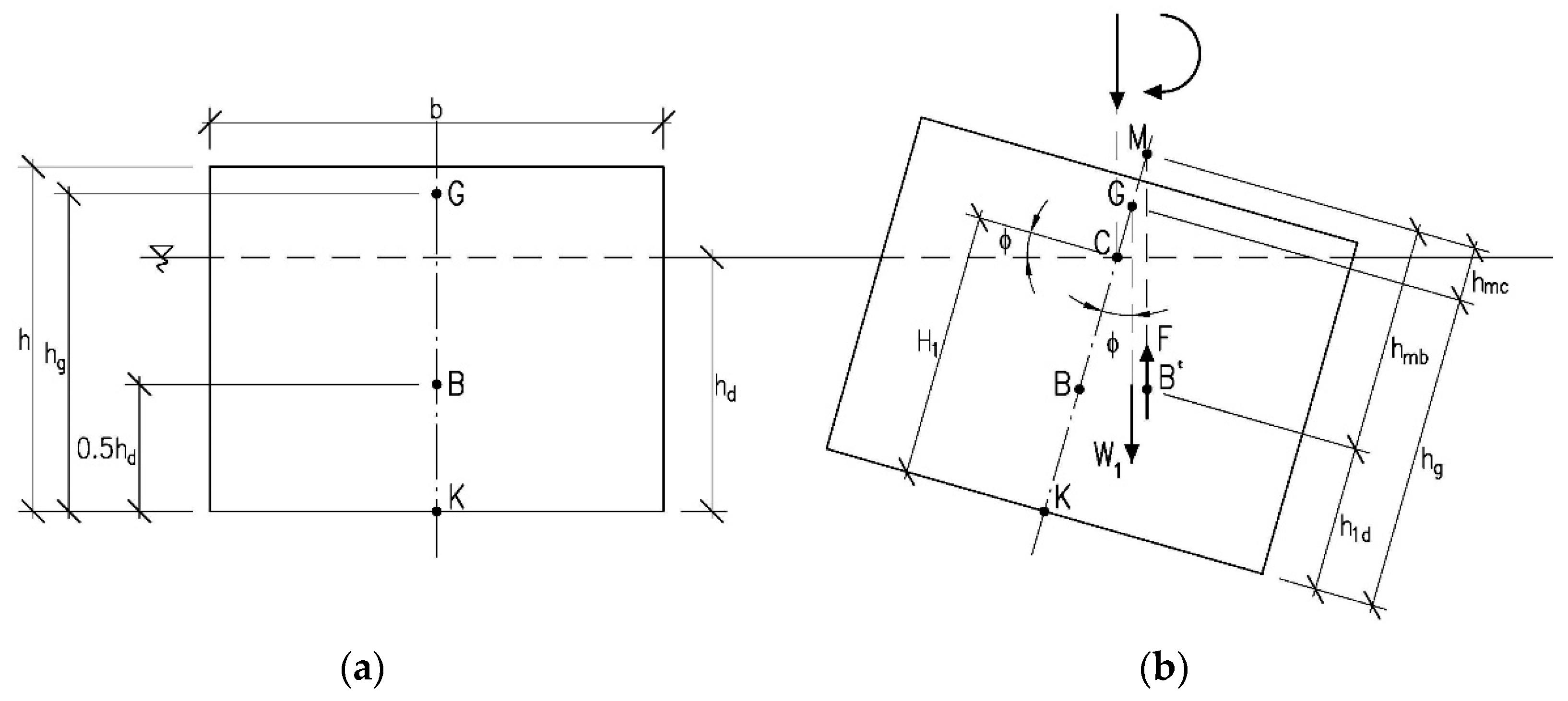
Figure 2.
Schematic drawing of the hydrostatic load acting on tank walls and the bottom (a) and uniform load acting on the upper plate (b) for which static calculations were made.
Figure 2.
Schematic drawing of the hydrostatic load acting on tank walls and the bottom (a) and uniform load acting on the upper plate (b) for which static calculations were made.
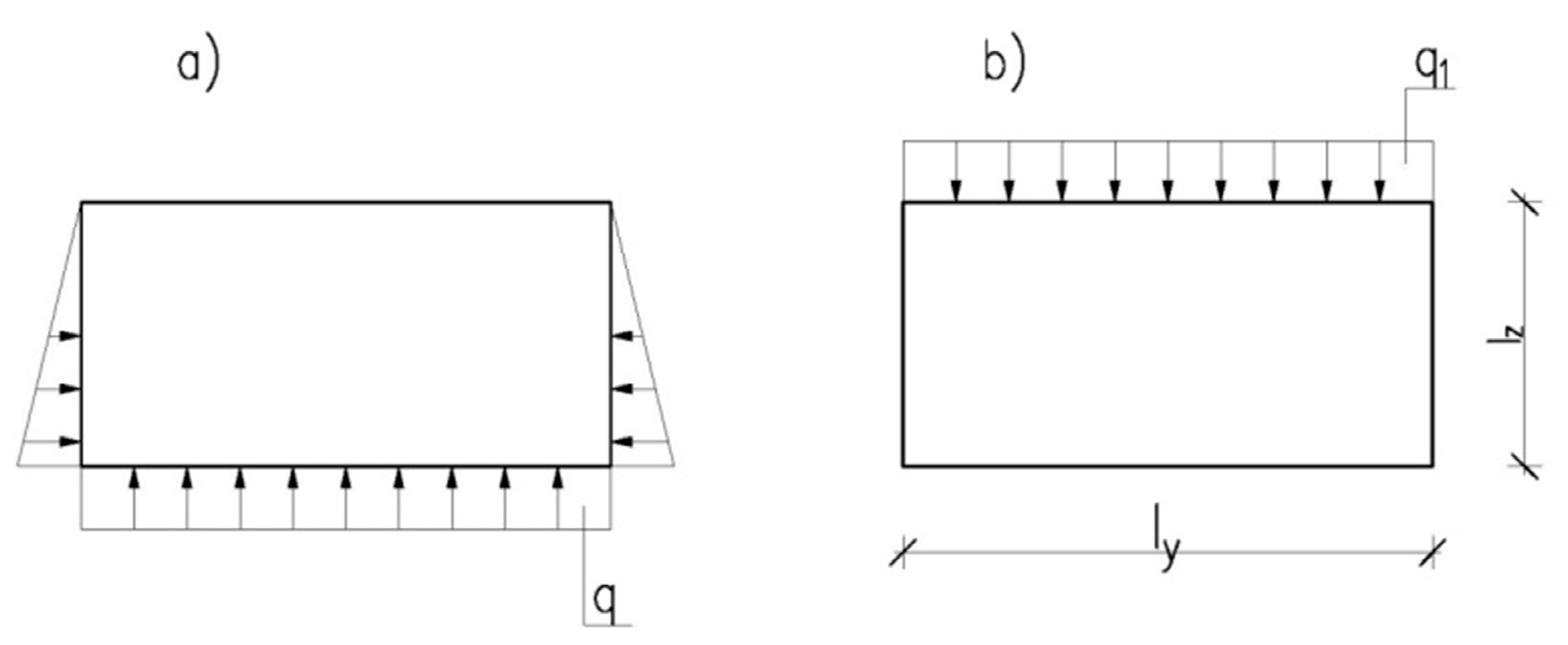
Figure 3.
Numbering and designation of characteristic points of the calculated tanks, for which Table 1 and Table 2 summarise coefficients proportional to bending moments and deflections.

Figure 4.
Variability pattern of selected bending moments depending on the thickness of the bottom at hydrostatic load acting on tank walls and uniform load acting on the bottom.
Figure 4.
Variability pattern of selected bending moments depending on the thickness of the bottom at hydrostatic load acting on tank walls and uniform load acting on the bottom.

Figure 5.
Variability pattern of selected bending moments depending on the thickness of the bottom at uniform load acting on the upper plate.
Figure 5.
Variability pattern of selected bending moments depending on the thickness of the bottom at uniform load acting on the upper plate.
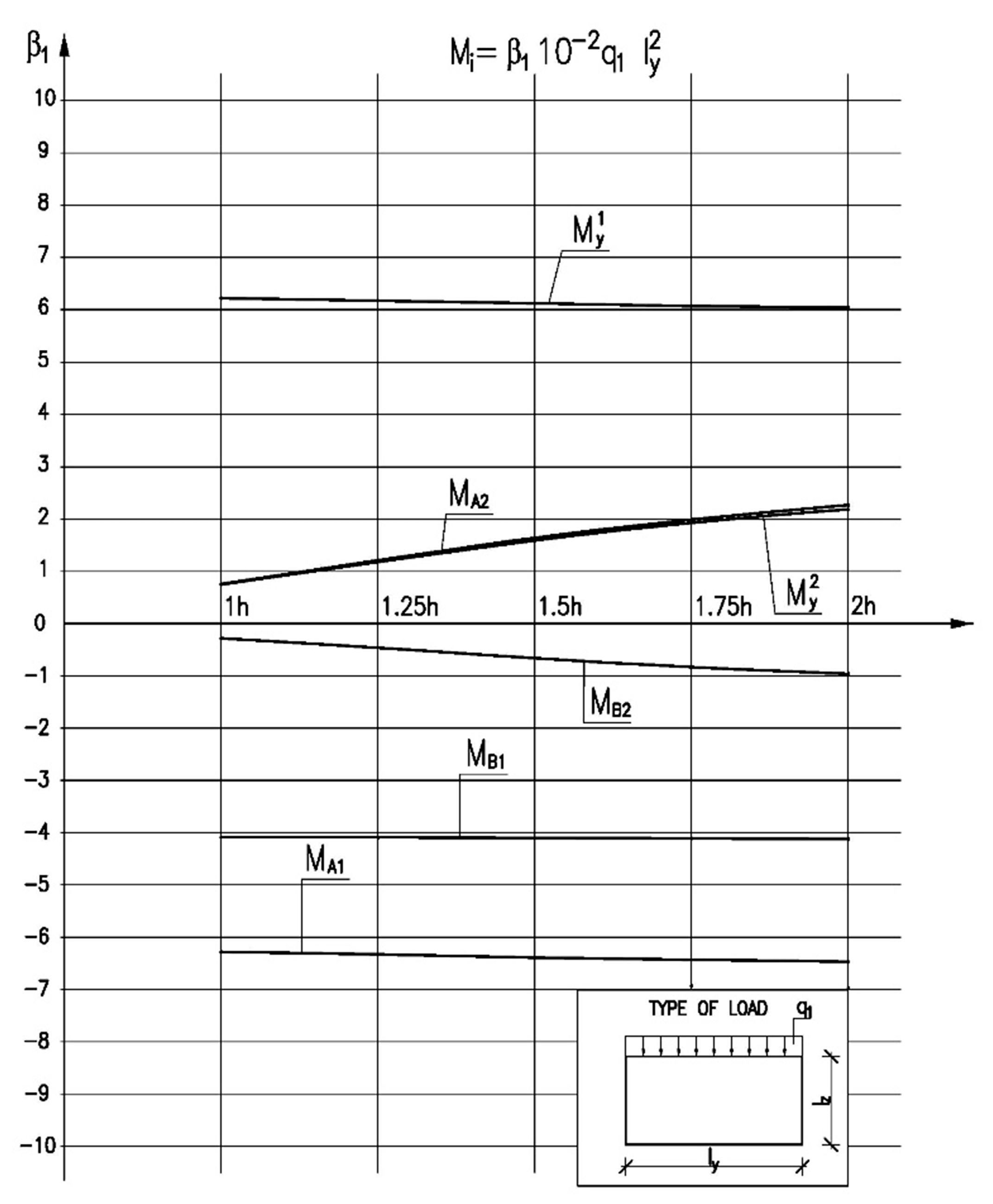
Figure 6.
Distribution of deflections in the cross-section in the middle of the tank length.

Figure 7.
Distribution of bending moments in the cross-section in the middle of the tank length.
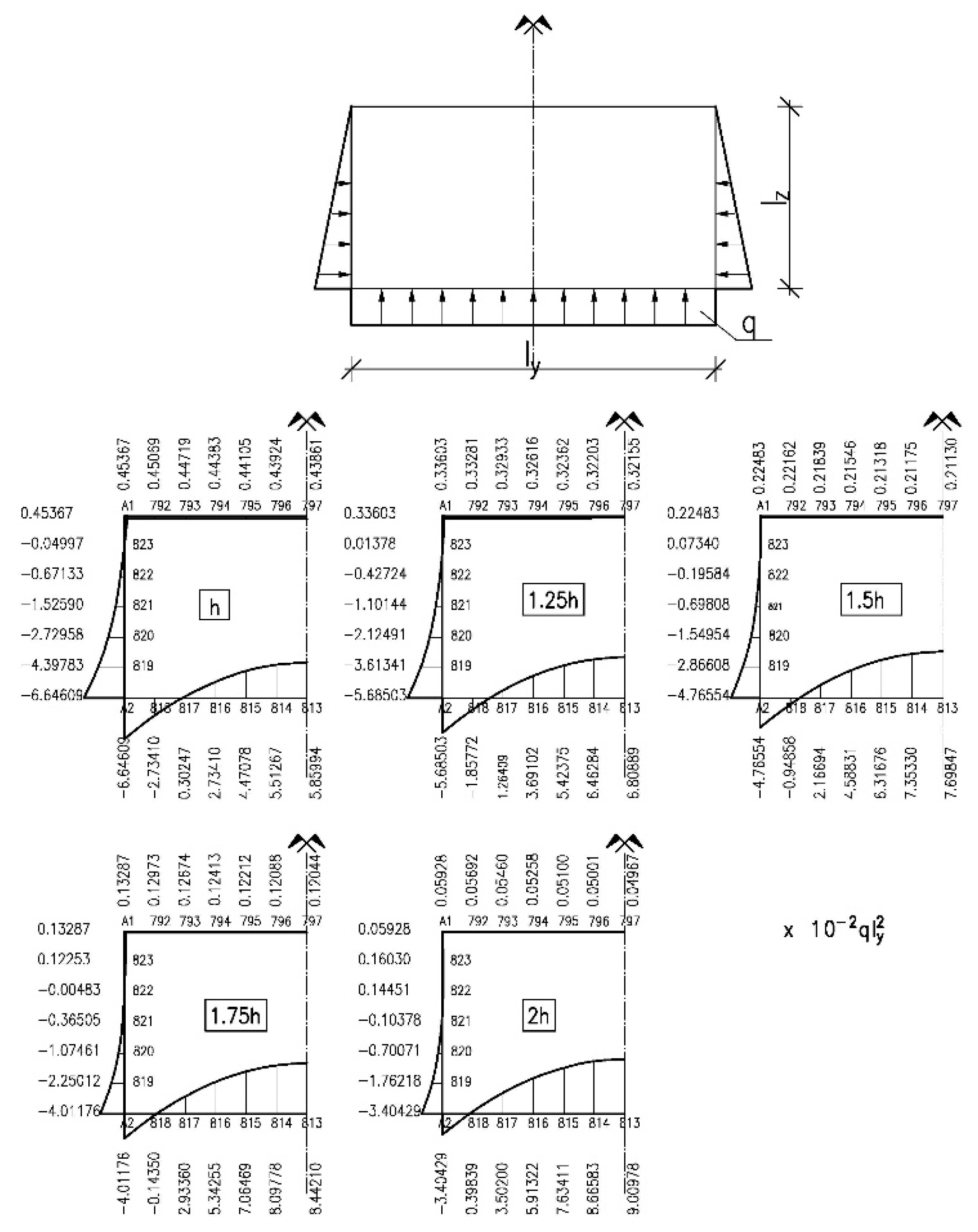
Figure 8.
Distribution of deflections in the cross-section in the middle of the tank length.
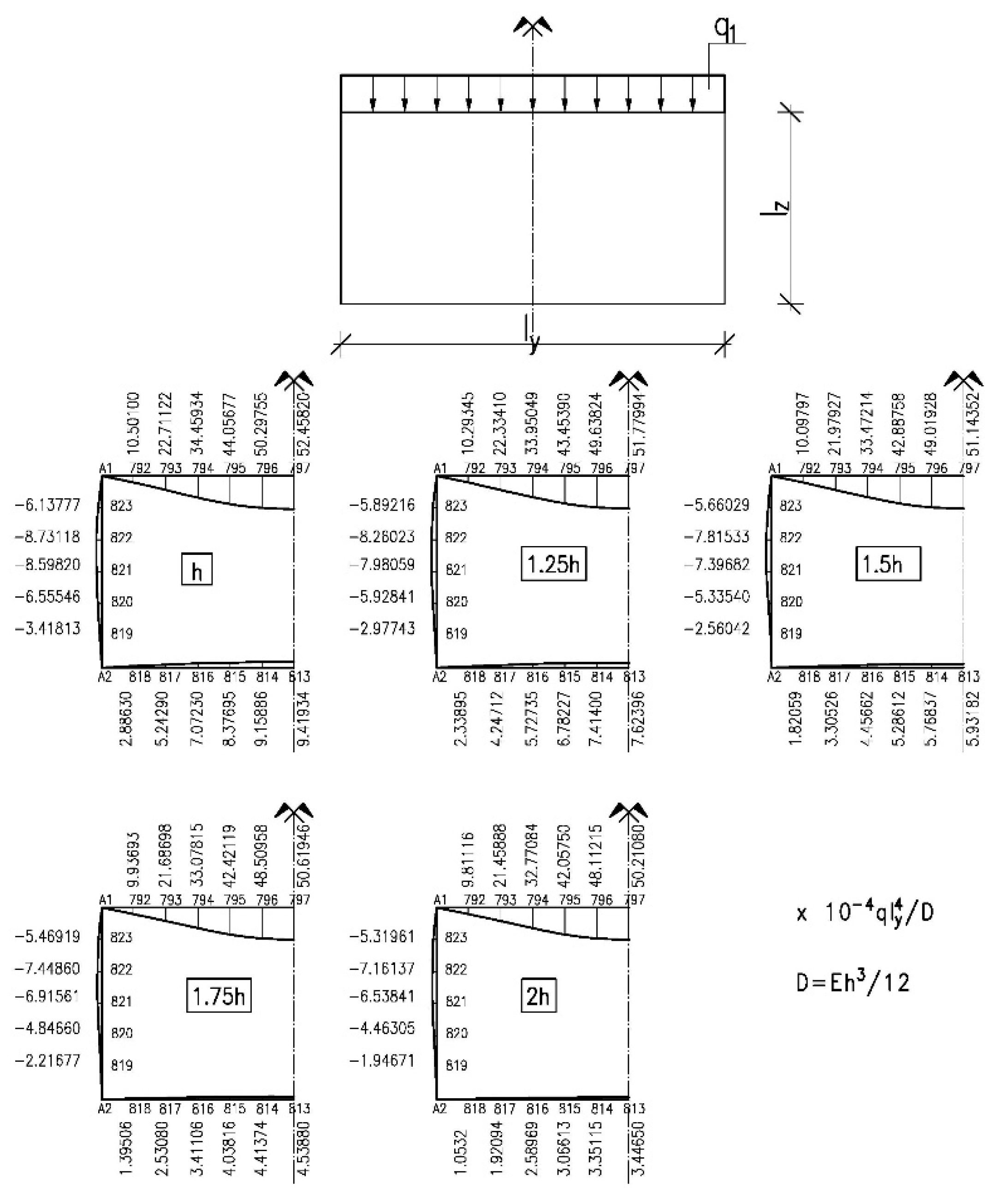
Figure 9.
Distribution of bending moments in the cross-section in the middle of the tank length.

Figure 10.
View of the tank during execution (left) and during launching at the test site (right) [7,34].

Table 1.
The β coefficients proportional to bending moments and deflections for closed monolithic tanks with proportional dimensions lx:ly:lz = 4:1:0.5, at hydrostatic load (Figure 2a).
Table 1.
The β coefficients proportional to bending moments and deflections for closed monolithic tanks with proportional dimensions lx:ly:lz = 4:1:0.5, at hydrostatic load (Figure 2a).
| Compared Value | Bottom Thickness in Relation to the Thickness of Tank Walls and the Upper Plate h | ||||
|---|---|---|---|---|---|
| 1 h | 1.25 h | 1.5 h | 1.75 h | 2 h | |
| w1 | 5.52276 | 4.05760 | 2.67487 | 1.53470 | 0.64370 |
| w2 | 47.92313 | 30.63693 | 21.04255 | 15.00900 | 10.94071 |
| Mx1 | 0.013431 | 0.01201 | 0.01015 | 0.00835 | 0.00642 |
| My1 | 0.43861 | 0.32156 | 0.21129 | 0.12044 | 0.04967 |
| Mx2 | 0.01189 | 0.02881 | 0.04903 | 0.07703 | 0.01040 |
| My2 | 5.85994 | 6.80889 | 7.69847 | 8.44210 | 9.00978 |
| Mx3 | −0.00469 | −0.00501 | −0.00475 | −0.00488 | −0.00333 |
| Mz3 | −1.52590 | −1.09941 | −0.69717 | −0.36497 | −0.10378 |
| My4 | −0.22551 | −0.16301 | −0.10056 | −0.05156 | −0.01411 |
| Mz4 | −0.04943 | 0.05892 | 0.18169 | 0.28149 | 0.36022 |
| MA1 | 0.45367 | 0.33603 | 0.22483 | 0.13288 | 0.05928 |
| MA2 | −6.64609 | −5.68503 | −4.76554 | −4.01176 | −3.40429 |
| MB1 | −0.03675 | −0.05803 | −0.09301 | −0.12098 | −0.14385 |
| MB2 | −4.47676 | −3.90449 | −3.32288 | −2.86228 | −2.50630 |
Table 2.
The β1 coefficients proportional to bending moments and deflections for closed monolithic tanks with proportional dimensions lx:ly:lz = 4:1:0.5, at uniform load on the upper plate (Figure 2b).
Table 2.
The β1 coefficients proportional to bending moments and deflections for closed monolithic tanks with proportional dimensions lx:ly:lz = 4:1:0.5, at uniform load on the upper plate (Figure 2b).
| Compared Value | Bottom Thickness in Relation to the Thickness of Tank Walls and the Upper Plate h | ||||
|---|---|---|---|---|---|
| 1 h | 1.25 h | 1.5 h | 1.75 h | 2 h | |
| w1 | 52.45820 | 51.77994 | 51.14352 | 50.61946 | 50.21080 |
| w2 | 9.41934 | 7.62396 | 5.93182 | 4.53880 | 3.44650 |
| Mx1 | 0.01328 | 0.01206 | 0.01068 | 0.00943 | 0.00825 |
| My1 | 6.22265 | 6.16866 | 6.11809 | 6.07649 | 6.04413 |
| Mx2 | 0.01493 | 0.02697 | 0.03994 | 0.05515 | 0.00761 |
| My2 | 0.75018 | 1.18460 | 1.59133 | 1.93058 | 2.18944 |
| Mx3 | −0.00531 | −0.00506 | −0.00451 | −0.00418 | −0.00325 |
| Mz3 | −2.75005 | −2.34321 | −2.36535 | −2.21184 | −2.09146 |
| My4 | −0.43140 | −0.40992 | −0.38776 | −0.36965 | −0.35549 |
| Mz4 | −0.90169 | −0.86478 | −0.82122 | −0.78400 | −0.75396 |
| MA1 | −6.28306 | −6.33845 | −6.39055 | −6.43357 | −6.46783 |
| MA2 | 0.76584 | 1.21608 | 1.64339 | 1.99491 | 2.27454 |
| MB1 | −4.09582 | −4.09701 | −4.10487 | −4.11243 | −4.11926 |
| MB2 | 0.27686 | 0.46413 | 0.66433 | 0.83138 | 0.96283 |
Table 3.
Results of buoyancy and stability calculations of the analysed tanks.
| Bottom Thickness of the Analysed Tanks (m) | Pontoon Buoyancy | Pontoon Stability with Half of the Upper Plate Loaded 1.0 kN/m2 | |||||
|---|---|---|---|---|---|---|---|
| At Self-Weight Load | At Uniform Load 3.0 kN/m2 | ||||||
| Immersion Depth hd (m) | Freeboardh f (m) | Immersion Depth hd (m) | Freeboardh f (m) | Metacentric Heighth mc (m) | Tilt Angle φ (°) | Freeboardh f (m) | |
| 0.08 | 0.66 | 0.59 | 0.96 | 0.29 | 0.35 | 7.16 | 0.38 |
| 0.10 | 0.71 | 0.54 | 1.01 | 0.24 | 0.37 | 6.38 | 0.35 |
| 0.12 | 0.75 | 0.50 | 1.05 | 0.20 | 0.38 | 5.86 | 0.32 |
| 0.14 | 0.80 | 0.45 | 1.10 | 0.15 | 0.41 | 5.15 | 0.29 |
| 0.16 | 0.84 | 0.41 | 1.14 | 0.11 | 0.42 | 4.77 | 0.26 |
Publisher’s Note: MDPI stays neutral with regard to jurisdictional claims in published maps and institutional affiliations. |
© 2020 by the author. Licensee MDPI, Basel, Switzerland. This article is an open access article distributed under the terms and conditions of the Creative Commons Attribution (CC BY) license (http://creativecommons.org/licenses/by/4.0/).
Share and Cite
MDPI and ACS Style
Szymczak-Graczyk, A. Numerical Analysis of the Bottom Thickness of Closed Rectangular Tanks Used as Pontoons. Appl. Sci. 2020, 10, 8082. https://doi.org/10.3390/app10228082
AMA Style
Szymczak-Graczyk A. Numerical Analysis of the Bottom Thickness of Closed Rectangular Tanks Used as Pontoons. Applied Sciences. 2020; 10(22):8082. https://doi.org/10.3390/app10228082
Chicago/Turabian StyleSzymczak-Graczyk, Anna. 2020. "Numerical Analysis of the Bottom Thickness of Closed Rectangular Tanks Used as Pontoons" Applied Sciences 10, no. 22: 8082. https://doi.org/10.3390/app10228082
Note that from the first issue of 2016, this journal uses article numbers instead of page numbers. See further details here.