Article

Effect of the Anti-Yaw Damper on Carbody Vertical Vibration and Ride Comfort of Railway Vehicle

by
Mădălina Dumitriu
1,* and
Dragoș Ionuț Stănică
2
1
Department of Railway Vehicles, University Politehnica of Bucharest, 060042 Bucharest, Romania
2
Doctoral School of Transports, University Politehnica of Bucharest, 060042 Bucharest, Romania
*
Author to whom correspondence should be addressed.
Appl. Sci. 2020, 10(22), 8167; https://doi.org/10.3390/app10228167
Submission received: 31 October 2020 / Revised: 13 November 2020 / Accepted: 13 November 2020 / Published: 18 November 2020
(This article belongs to the Section Mechanical Engineering)

Abstract

:
The theoretical research on means to reduce the vertical vibrations and improve the ride comfort of the railway vehicle relies on a mechanical model obtained from the simplified representation of the vehicle, while considering the important factors and elements affecting the vibration behaviour of the carbody. One of these elements is the anti-yaw damper, mounted longitudinally, between the bogie and the vehicle carbody. The anti-yaw damper reduces the lateral vibrations and inhibits the yaw motion of the vehicle, a reason for which this element is not usually introduced in the vehicle model when studying the vertical vibrations. Nevertheless, due to the position of the clamping points of the anti-yaw damper onto the carbody and the bogie, the damping force is generated not only in the yawing direction but also in the vertical and longitudinal directions. These forces act upon the vehicle carbody, impacting its vertical vibration behaviour. The paper analyzes the effect of the anti-winding damper on the vertical vibrations of the railway vehicle carbody and the ride comfort, based on the results derived from the numerical simulations. They highlight the influence of the damping, stiffness and the damper mounting angle on the power spectral density of the carbody vertical acceleration and the ride comfort index.

1. Introduction

Duringtrain travel, passenger comfort can be affected by several factors, some due to the movement of the railway vehicle, such as vibrations and noise, while others coming from the environmentalconditions inside the vehicle—temperature, humidity and airspeed, lighting, or the interior fittings and decor (for instance, the shape and placement of chairs) [1,2,3]. Among all factors affecting the passengers’ comfort, vibrations are paid special attention, as their effect upon the human body is very important [4,5]. As a function of vibrations intensity, direction and frequency value they occur at, as well as the exposure time, vibrations can perturb the comfort and the ability of passengers to conduct certain sedentary activities and even their health condition. Generally, the vibrations of the railway vehicle are considered to be the main factor in determining the ride comfort [1,2,3,6,7,8].
The railway vehicle vibrations are mainly caused by track irregularities [9,10,11,12,13]. The track geometric irregularities mainly come from construction imperfections, track exploitation, changes in infrastructure due to the action of environmental factors or soil movements [14] and also the irregularities in the rolling surfaces of railway rails. To these, the discontinuity of the rails are added—joints, switches and crossings. Rolling on a track with irregularities generates vibrations on the wheelsets that are transmitted to the bogies and further to the carbody, by means of the suspension and the connecting elements between the bogie and the carbody. To achieve good ride comfort, these vibrations have to be suppressed, asride comfort is negatively affected by high accelerations in the carbody [15].
The topic of reducing the vertical vibrations in the carbody [15,16,17,18,19,20,21,22,23,24,25,26] and the improvement of ride comfort [27,28,29,30] is a research matter of high interest, especially for the lightweight carbody of the high-speed vehicles. A lighter weight of the carbody significantly contributes to a higher speed, lower energy consumption, reduction in the ground vibration, and construction-cost saving [31,32]. The lighter the vehicle carbody, the higher its flexibility that will thus facilitate an easy excitation of the carbody structural vibrations to harm the ride comfort. Even though the carbody structural vibrations are rather complex, the greatest influence upon ride comfort comes from the first carbody vertical bending mode [33] whose frequency usually ranges from 6 to 11 Hz, an interval where the human body shows a higher sensitivity to vertical vibrations.
The railway vehicle modelling is the starting point of all the theoretical research studies regarding the means to reduce the vertical vibrations of the carbody and to improve the ride comfort. In principle, the mechanical model of the railway vehicleis obtained by a simplified representation of the railway vehicle, while taking into account the important factors affecting the behavior of vibrations of the vehicle. One of these factors is the structural flexibility of the vehicle carbody, a reason for which the carbody is always represented by a “flexible carbody” [34,35] type model. The “flexible carbody” type models vary from Euler–Bernoulli [11,19,23,24] or Timoshenko [10,36] beams, to structure-typetridimensional models [31], multi-body models [27], models based on the finite element method [33] or combinations of models based on multi-body systems and the finite element method [37].
Other elements that influence the vertical vibration behavior of the railway vehicle are the longitudinal connecting elements between the bogie and the carbody, such as traction devices and anti-yaw dampers, albeit more rarely included in the vehicle model. The authors of this paper have introduced the longitudinal traction system between the carbody and bogie in the vehicle model as a Kelvin–Voigt system in several pieces of researches. These research studies aimed to analyze the vertical bending vibrations of the carbody and their influence on the ride comfort [38,39], as well as the means to reduce these vibrations and improve the ride comfort [23,28,29,30,40].
Given the role of the anti-yaw damper, to reduce the lateral vibrations and inhibit the yaw motion in the vehicle [41,42,43], this damper is not usually introduced in the vehicle model when studying the vertical vibrations.Nevertheless, it is worth mentioning that the damping force is generated not only in the yawing direction but also in the vertical and longitudinal directions [44], due to the unfavorable position of the clamping points of the anti-yaw damper to the carbody and the bogie. These forces act upon the vehicle carbody, affecting its vertical vibration behavior. The research studies in this direction are very limited, which is why only two studies regarding the influence of the yaw dampers on vertical vibration of railway vehicle carbody [44,45] have been identified. These studies have explored the effect of yaw dampers on the carbody vertical vibration induced by the rotation of imbalanced wheelsets, which is shown to be based on the results of an excitation test of a full-scale vehicle. Vibration measurement tests were performed using a test vehicle with/without yaw dampers. To suppress the vibration transmission from the bogie to the carbody through yaw dampers, a new mounting structure of yaw dampers has been devised.
The present paper analyzes the effect of the anti-yaw damper upon the vertical vibration behavior of the railway vehicle carbody and the ride comfort at vertical vibrations. To this purpose, the results derived from numerical simulations developed based on a rigid-flexible coupled type vehicle model are used, where the carbody is represented via an Euler–Bernoulli equivalent beam, while the bogies and the wheelsets are modelled through rigid bodies. This model is used regularly in the theoretical researchof vertical vibrations and ride comfort of the railway vehicle thanks to the fact that it ensures a good agreement between numerical simulations and field tests [24,28,32,39]. The two levels of the vertical suspension of the vehicle are modelled through Kelvin–Voigt systems and the anti-yaw damper through a Maxwell model. The effect of the anti-yaw damper is highlighted through the influence of the damping, stiffness and the mounting angle of the damper upon the power spectral density of the carbody vertical vibration and upon the ride comfort index, calculated in three reference points of the carbody. These points are located at the center of the carbody and against the bogies and are considered critical points from the ride comfort perspective [34,46].

2. Mechanical Model of Railway Vehicle

To study the effect of the anti-yaw damper upon the vertical vibrations of the railway vehicles carbody during running on a track with irregularities, a model of the rigid-flexible coupled type vehicle is being considered.The model is featured in Figure 1. As for the track model, the rigid track hypothesis is adopted, an approach justified by the fact that the eigenfrequencies of the vertical vibrations of the vehicle carbody, relevant from the ride comfort viewpoint, are much smaller than the frequencies in the wheelset-track system.
The vehicle carbody is represented through a free-free equivalent beam, with a constant section and uniformly distributed mass, Euler–Bernoulli type. This model allows considering the vertical vibration modes of the carbody, relevant for the ride comfort, i.e., the vibration rigid modes–bounce zc, pitch θc, and the first vertical bending mode. The vertical displacement of the carbody medium fiber wc(x,t) is the result of the overlapping of the three vibration modes,
w c ( x , t ) = z c ( t ) + ( x L c 2 ) θ c ( t ) + X c ( x ) T c ( t ) ,
where Lc represents the carbody length, Tc(t) is the coordinate of the carbody bending and Xc(x) represents the natural function of this vibration mode, described in the equation
X c ( x ) = sin β x + sinh β x ( sin β L c sinh β L c ) ( cos β x + cosh β x ) cos β L c cosh β L c ,
with   β = ω c 2 ρ c E I 4   and cos β L c cosh β L c = 1 ,
where ωc is the natural angular frequency of the carbody bending, and ρc = mc/Lc where mc is carbody mass and Lc is length of carbody.
Due to the fact that bogies and wheelsets feature reduced elastic deformations, they are represented with rigid bodies. The vibration modes of the two bogies in the vertical plane are the bounce zb1,2 and pitch θb1,2. The vertical displacements of the wheelsets zw1...4 are equal to the vertical track irregularities against each wheelset.
Each wheelset is connected to the bogie chassis through a Kelvin–Voigt system that models the primary suspension, with the elastic constant 2kzb and damping constant 2czb. The bogie is connected to the carbody through a secondary suspension, modelled via a Kelvin–Voigt system, with the elastic constant 2kzc and damping constant 2czc. The anti-yaw damper is represented through a Maxwell model, where the anti-yaw damper stiffness is rendered via an elastic element of stiffness k, whereas the anti-yaw damping is modelled through a damping element c.The angle α stands for the mounting angle of the anti-yaw damper.

3. Equations of Motion

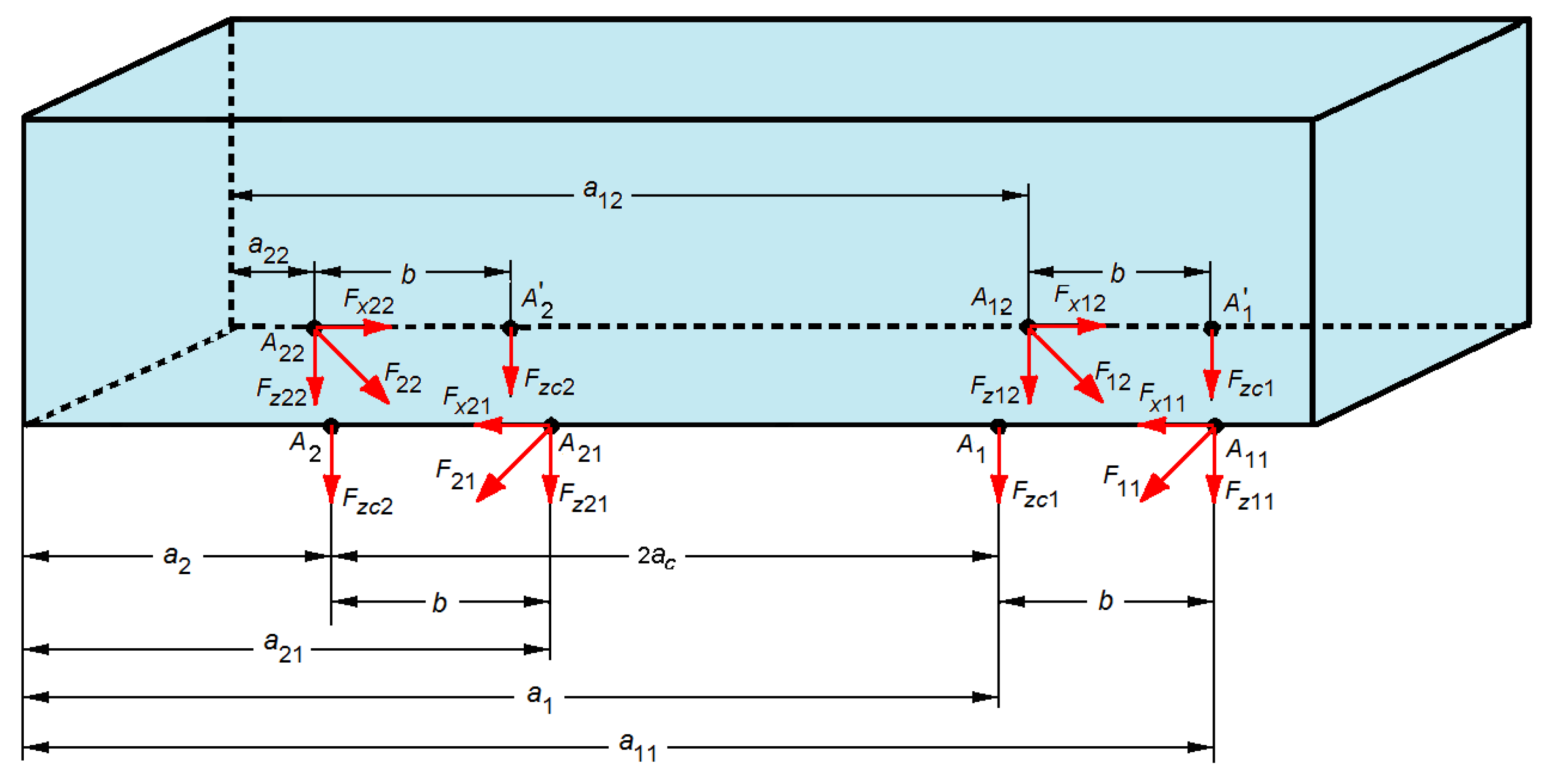
Figure 2 features the forces due to the secondary suspension and the anti-yaw damper acting upon the vehicle carbody. In the carbody supporting points on the secondary suspension, A i and A i , operate the forces Fzci (for i = 1, 2),
F z c i = c z c ( w c ( a i , t ) t z ˙ b i ) k z c [ w c ( a i , t ) z b i ] ,
where distances ai = Lc/2 ± ac fix the position of the supporting point of the carbody on the secondary suspension, with 2ac—carbody wheelbase.
The anti-yaw dampers are fixed to the vehicle carbody in the points Aik, where k = 1, 2. In these points, the forces Fik are acting, with the following components on vertical and longitudinal directions:
F z i k = k [ w ( a i k , t ) sin α + ( 1 ) k 1 h w ( a i k , t ) x cos α Δ l i k ] sin α ,
F x i k = k [ w ( a i k , t ) sin α + ( 1 ) k 1 h w ( a i k , t ) x cos α Δ l i k ] cos α ,
where Δlik are the internal displacements of the elements in the Maxwell systems; distances aik = Lc/2 + (−1)k−1ac + (−1)k−1b fix the position of the clamping points to the carbody for the anti-yaw dampers; b represents the distance between the clamping point to the carbody of the anti-yaw damper and the carbody supporting point onto the secondary suspension, while h is the distance between the carbody medium fiber and the clamping plan of the anti-yaw dampers onto the carbody.
The motion equation of the carbody vehicle has the general form,
E I 4 w c ( x , t ) x 4 + μ I 5 w c ( x , t ) x 4 t + ρ c 2 w c ( x , t ) t 2 = i = 1 2 ( 2 F z c i δ ( x a i ) + k = 1 2 F z i k δ ( x a i k ) ) i = 1 2 k = 1 2 ( 1 ) j 1 F x i k δ ( x a i k )  
where EI is bending modulus (E—longitudinal modulus of elasticity, and I—inertia moment of the beam’s transversal section), µ—structural damping coefficient, and δ(.) is Dirac’s delta function.
By applying the modal analysis method and considering the orthogonality property of the eigenfunction of the carbody vertical bending, Equation (7) turns into three two-order differential equations with ordinary derivatives, to describe the motions of bounce, pitch, and bending of the carbody,
m c z ¨ c = i = 1 2 ( 2 F z c i + k = 1 2 F z i k ) ,
J c θ ¨ c = i = 1 2 [ 2 F z c i ( a i L c 2 ) + k = 1 2 F z i k ( a i k L c 2 ) ] + h i = 1 2 k = 1 2 ( 1 ) k F x i k ,
m m c T ¨ c + c m c T ˙ c + k m c T c = i = 1 2 ( 2 F z c i X c ( a i ) + k = 1 2 F z i k X c ( a i k ) ) + h i = 1 2 k = 1 2 ( 1 ) k F x i k d X c ( a i k ) d x ,
where Jc is the carbody inertia moment, and kmc, cmc and mmc, are the stiffness, damping and the carbody modal mass,
k m c = E I 0 L ( d 2 X c d x 2 ) 2 d x ,   c m c = μ I 0 L ( d 2 X c d x 2 ) 2 d x ,   m m c = ρ c 0 L X c 2 d x .
Based on the property of symmetry of the eigenfunction Xc(x), the following notations will be used:
X c ( a 1 ) = X c ( a 2 ) = λ 1 , X c ( a 11 ) = X c ( a 22 ) = λ 2 ,   X c ( a 12 ) = X c ( a 21 ) = λ 3 , X c ( a 11 ) = X c ( a 22 ) = λ 4 ,   X c ( a 12 ) = X c ( a 21 ) = λ 5 .
If the relations (4)–(6) are replaced in the motion equations of the carbody, they become:
m c z ¨ c + 2 c z c [ 2 z ˙ c + 2 λ 1 T ˙ c ( z ˙ b 1 z ˙ b 2 ) ] + 2 k z c [ 2 z c + 2 λ 1 T c ( z b 1 + z b 2 ) ] + + k { [ 4 z c + 2 ( λ 2 + λ 3 ) ] sin α + 2 h ( λ 4 λ 5 ) T c cos α ( Δ l 11 + Δ l 12 + Δ l 21 + Δ l 22 ) } sin α = 0
J c θ ¨ c + 2 c z c a c [ 2 a c θ ˙ c ( z ˙ b 1 z ˙ b 2 ) ] + 2 k z c a c [ 2 a c θ ˙ c ( z b 1 z b 2 ) ] + + k [ ( a c + b ) sin α + h cos α ] [ 2 ( a c + b ) θ c sin α + 2 h θ c cos α ( Δ l 11 Δ l 22 ) ] + + k [ ( a c b ) sin α h cos α ] [ 2 ( a c b ) θ c sin α 2 h θ c cos α ( Δ l 12 Δ l 21 ) ] = 0  
m m c T ¨ c + c m c T ˙ c + k m c T c + 2 c z c λ 1 [ 2 z ˙ c + 2 λ 1 T ˙ c ( z ˙ b 1 z ˙ b 2 ) ] + 2 k z c λ 1 [ 2 z c + 2 λ 1 T c ( z b 1 + z b 2 ) ] + + k ( λ 2 sin α + h λ 4 cos α ) [ 2 ( z c + λ 2 T c ) sin α + 2 h λ 4 T c cos α ( Δ l 11 + Δ l 22 ) ] + + k ( λ 3 sin α h λ 5 cos α ) [ 2 ( z c + λ 3 T c ) sin α 2 h λ 5 T c cos α ( Δ l 12 + Δ l 21 ) ] = 0 .
The motion equations of the bounce and pitch of the bogies are
m b z ¨ b i = j = 2 i 1 2 i F z b j 2 F z c i i = 1 2 k = 1 2 F z i k ,   for   i = 1 ,   2 ,
J b θ ¨ b i = a b j = 2 i 1 2 i ( 1 ) j + 1 F z b j ,   for   i = 1 ,   2 ,
where mb represents the bogie suspended mass, Jb is the inertia moment of the bogie, and 2ab is the bogie wheelbase; Fzbj represent the forces due to the primary suspension corresponding to the wheelset j, namely (j + 1).
After processing, the Equations (16) and (17) are as such,
m b z ¨ b 1 + 2 c z b [ 2 z ˙ b 1 ( z ˙ w 1 + z ˙ w 2 ) ] + 2 k z b [ 2 z b 1 ( z w 1 + z w 2 ) ] + + 2 c z c ( z ˙ b 1 z ˙ c a c θ ˙ c λ 1 T ˙ c ) + 2 k z c ( z b 1 z c a c θ c λ 1 T c ) k { [ 2 z c + 2 a c θ c + ( λ 2 + λ 3 ) T c ] sin α + h ( λ 4 λ 5 ) T c cos α ( Δ l 11 Δ l 12 ) } sin α = 0
m b z ¨ b 2 + 2 c z b [ 2 z ˙ b 2 ( z ˙ w 3 + z ˙ w 4 ) ] + 2 k z b [ 2 z b 2 ( z w 3 + z w 4 ) ] + + 2 c z c ( z ˙ b 2 z ˙ c + a c θ ˙ c λ 1 T ˙ c ) + 2 k z c ( z b 2 z c + a c θ c λ 1 T c ) k { [ 2 z c 2 a c θ c + ( λ 2 + λ 3 ) T c ] sin α + h ( λ 4 λ 5 ) T c cos α ( Δ l 21 Δ l 22 ) } sin α = 0
J b θ ¨ b 1 + 2 a b c z b [ 2 a b θ ˙ b 1 ( z ˙ w 1 z ˙ w 2 ) ] + 2 a b k z b [ 2 a b θ b 1 ( z w 1 z w 2 ) ] = 0
J b θ ¨ b 2 + 2 a b c z b [ 2 a b θ ˙ b 2 ( z ˙ w 3 z ˙ w 4 ) ] + 2 a b k z b [ 2 a b θ b 2 ( z w 3 z w 4 ) ] = 0 .
The equations of the Maxwell systems are as below,
c Δ l ˙ 11 , 22 + k Δ l 11 , 22 c z ˙ b 1 , 2 sin α k { [ z c ± ( a c + b ) θ c + λ 2 T c ] sin α ± h ( θ c ± λ 4 T c ) cos α } = 0 ,
c Δ l ˙ 12 , 21 + k Δ l 12 , 21 c z ˙ b 1 , 2 sin α k { [ z c ± ( a c b ) θ c + λ 3 T c ] sin α h ( θ c ± λ 5 T c ) cos α } = 0 .

4. The Vehicle Dynamic Response to the Track Vertical Irregularities

The track vertical irregularities are considered to be represented as a stationary stochastic process, which can be described via the power spectral density. The theoretical curve of the power spectral density is representative ofthe average statistical properties of the European railway, as in the relation [47]
S ( Ω ) = A Ω c 2 ( Ω 2 + Ω r 2 ) ( Ω 2 + Ω c 2 ) ,
where Ω is the wavelength, Ωc = 0.8246 rad/m, Ωr = 0.0206 rad/m, and A is a coefficient depending on the track quality. For a high-level quality track, A = 4.032·10−7 radm, whereas for a low-level quality, the coefficient A is 1.080·10−6 radm.
As a function of the angular frequency ω = VΩ, where V is the vehicle velocity, the power spectral density of the track irregularities can be written in the below form
G ( ω ) = S ( ω / V ) V = A Ω c 2 V 3 [ ω 2 + ( V Ω c ) 2 ] [ ω 2 + ( V Ω r ) 2 ] .
In terms of ride comfort, what interests is the dynamic response in three carbody reference points, located at the carbody center and against the two bogies. The response functions of the vertical acceleration at the carbody center H ¯ C ( ω ) and in the points above the two bogies H ¯ B 1 , 2 ( ω ) , respectively, are expressed in the below equations
H ¯ C ( ω ) = ω 2 [ H ¯ z c ( ω ) + X c ( L c / 2 ) H ¯ T c ( ω ) ] ,
H ¯ B 1 , 2 ( ω ) = ω 2 [ H ¯ z c ( ω ) ± a c H ¯ θ c ( ω ) + X c ( l 1 , 2 ) H ¯ T c ( ω ) ] ,
where H ¯ z c ( ω ) , H ¯ θ c ( ω ) , H ¯ T c ( ω ) are the frequency response functions corresponding to the bounce, pitch and vertical bending of the carbody.
Starting from the response functions of the vertical acceleration of the carbody and the power spectral density of the track irregularities, the power spectral density of the carbody vertical acceleration in three carbody reference points can be calculated as
G C ( ω ) = ω 4 G ( ω ) [ H ¯ z c ( ω ) + X c ( L c / 2 ) H ¯ T c ( ω ) ] 2 ,
G B 1 , 2 ( ω ) = ω 4 G ( ω ) [ H ¯ z c ( ω ) ± a c H ¯ θ c ( ω ) + X c ( l 1 , 2 ) H ¯ T c ( ω ) ]   2 ,
To determine the ride comfort index, it is required to calculate the root mean square of the carbody vertical acceleration. This is calculated based on the dynamic response of the vehicle carbody, expressed as the power spectral density of acceleration,
a C = 1 π G C ( ω ) d ω   ,   a B 1 , 2 = 1 π G B 1 , 2 ( ω ) d ω

5. Evaluation of Ride Comfort during Vertical Vibrations

According to the UIC 513R leaflet [48] and the standard of railway applications EN 12299 [49], the quantification of the comfort to vibrations is performed using a parameter, called ride comfort index (NMV), and with a conventional scale linking the values of this index and the comfort sensation (see Table 1).
The ride comfort index is calculated with the general relation [48,49]
N M V = 6 ( a X 95 W a d ) 2 + ( a Y 95 W a d ) 2 + ( a Z 95 W a b ) 2 ,
where aX, aY and aZ are the root mean square of the longitudinal, lateral and vertical carbody acceleration, 95 refers to the quantile of order 95%, and Wad, Wab represent the weighting filters of the longitudinal, lateral, respectively vertical acceleration.
To evaluate the ride comfort at vertical vibration, the partial comfort index is used, which is calculated with the general relation [49]
N M V Z = 6 a Z 95 W a b ,
where Wab = Wa.Wb represents the weighting filter of the vertical acceleration.
The filter Wa is a passband filter with the following frequency weighting function
H a ( s ) = s 2 ( 2 π f 2 ) 2 [ s 2 + 2 π f 1 Q 1 s + ( 2 π f 1 ) 2 ] [ s 2 + 2 π f 2 Q 1 s + ( 2 π f 2 ) 2 ] ,
where s = iω (with i2 = −1), f1 = 0.4 Hz, f2 = 100 Hz and Q1 = 0.71.
The filter Wb takes into account the high human sensitivity to the vertical vibrations within the frequency interval of 4 Hz and 12 Hz and has the frequency weighting function in the form of
H b ( s ) = ( s + 2 π f 3 ) [ s 2 + 2 π f 5 Q 3 s + ( 2 π f 5 ) 2 ] 2 π K f 4 2 f 6 2 [ s 2 + 2 π f 4 Q 2 s + ( 2 π f 4 ) 2 ] [ s 2 + 2 π f 6 Q 4 s + ( 2 π f 6 ) 2 ] f 3 f 5 2 ,
where f3 = 16 Hz, f4 = 16 Hz, f5 = 2.5 Hz, f6 = 4 Hz, Q2 = 0.63, Q4 = 0.8 and K = 0.4.
When adopting the hypothesis that the vertical accelerations have a Gaussian distribution with the null mean value, we will have the following relation to calculate the partial ride comfort index in the carbody reference points
N M V C = 6 Φ 1 ( 0.95 ) 1 π G C ( ω ) | H a b ( ω ) | 2 d ω   ,
N M V B 1 , 2 = 6 Φ 1 ( 0.95 ) 1 π G B 1 , 2 ( ω ) | H a b ( ω ) | 2 d ω   ,
where Φ 1 ( 0.95 ) represents the quantile of the standard Gaussian distribution with the probability of 95% and Hab(ω) = Ha(ω)·Hb(ω), where Ha(ω) and Hb(ω) are the frequency weighting function corresponding to the filters Wa and Wb.

6. Results of Numerical Simulationsand Discussion

This section examines the effect of the anti-yaw damper upon the carbody vertical vibrations and the ride comfort of the railway vehicles, by using to this purpose the results from numerical simulations. The characteristics of the vertical vibration behavior of the vehicle carbody are looked at based on the power spectral density of the vertical acceleration in the carbody reference points. To evaluate the ride comfort at the vertical vibrations, the ride comfort index calculated in the carbody reference points is being used. The reference parameters of the vehicle model are featured in Table 2. It is considered that the vehicle is traveling on a low-quality track, described by the coefficient A = 1.080·10−6 radm.
The eigenfrequencies of the vertical vibration modes of the carbody, corresponding to the reference parameters of the model without anti-yaw damper are the following: bounce eigenfrequency—1.17 Hz; pitch eigenfrequency—1.46 Hz; bending eigenfrequency—8 Hz.
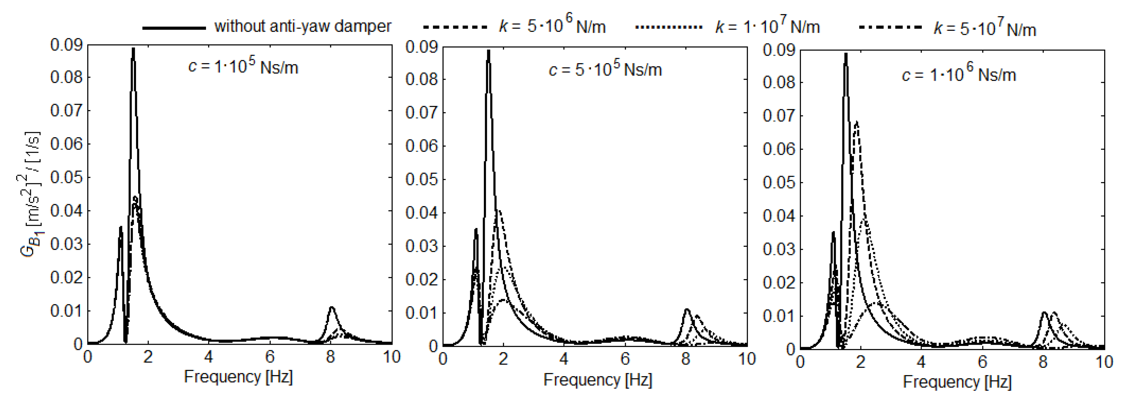
Figure 3, Figure 4 and Figure 5 show the influence of the damping and stiffness of the anti-yaw damper upon the power spectral density of the acceleration in the carbody reference points at the velocity of 300 km/h. The mounting angle of the anti-yaw damper is 10 degrees.
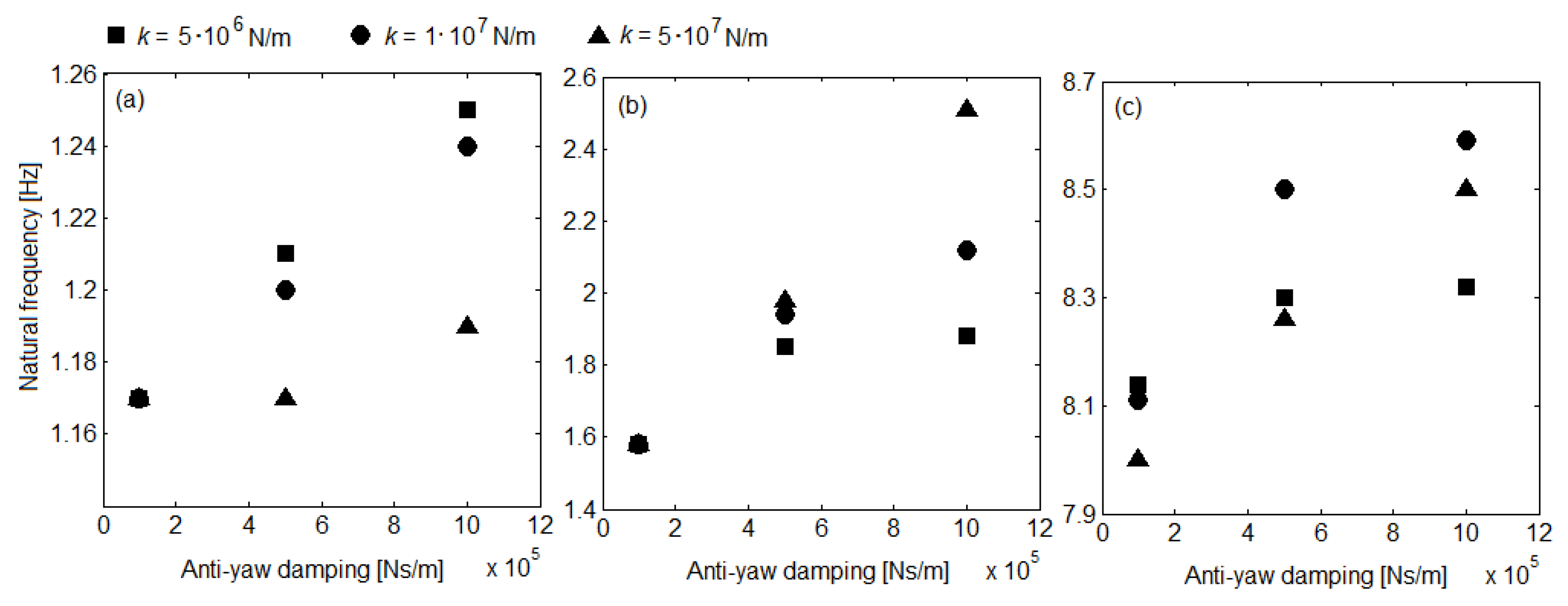
One observation concerns the increase of the eigenfrequencies of the carbody vibration modes. The increased eigenfrequencies areall the more pronounced the higher the anti-yaw damping, as seen in Figure 6. As for the influence of the anti-yaw damper stiffness, this manifests differently at the three carbody eigenfrequencies and is linked to the value of the anti-yaw damping. For c = 1·105 Ns/m, the increase in the anti-yaw damper stiffness does not affect the carbody bounce and pitch eigenfrequencies, yet triggers the reduction in the bending eigenfrequency (see Figure 6). For higher values of the anti-yaw damping, the following situations are encountered—the carbody bounce frequency decreases and the carbody pitch frequency increases along with the rise in the anti-yaw damper stiffness; the carbody bending frequency rises with the increase in the anti-yaw damper stiffness from 5·106 N/m to 1·107 N/m and then decreases down for further growth at 5·107 N/m.
Another observation based on the results in Figure 3, Figure 4 and Figure 5 refers to the fact that the anti-yaw damper results in the reduction of the carbody vibrations at the eigenfrequencies of the three vibration modes. This reduction is all the more effective as the stiffness of the anti-yaw damper is higher, which is also highlighted in the diagrams in Figure 7. These are obtained for c = 5·105 Ns/m,α = 10 degrees, and various values of the anti-yaw damper stiffness ranging from 106 N/m to 108 N/m, proving the fact that the power spectral density of the acceleration continually decreases along with the increase in the anti-yaw damper stiffness. In terms of the anti-yaw damping effect upon the reduction in the vibrations of the carbody at the eigenfrequencies of the three vibration modes, this is examined by means of the diagrams in Figure 8, calculated for k = 1·107 N/m, α = 10 degrees and c within the interval of 1·105 Ns/m … 5·106 Ns/m. The power spectral density of the acceleration is noticed to continually decrease by increasing the damping up to a certain value. Should the anti-yaw damping keeps rising over this value, the power spectral density of the acceleration in the carbody starts going up.In conclusion, for a certain value of the anti-yaw damping, the minimum value of the power spectral density of the carbody acceleration is obtained.
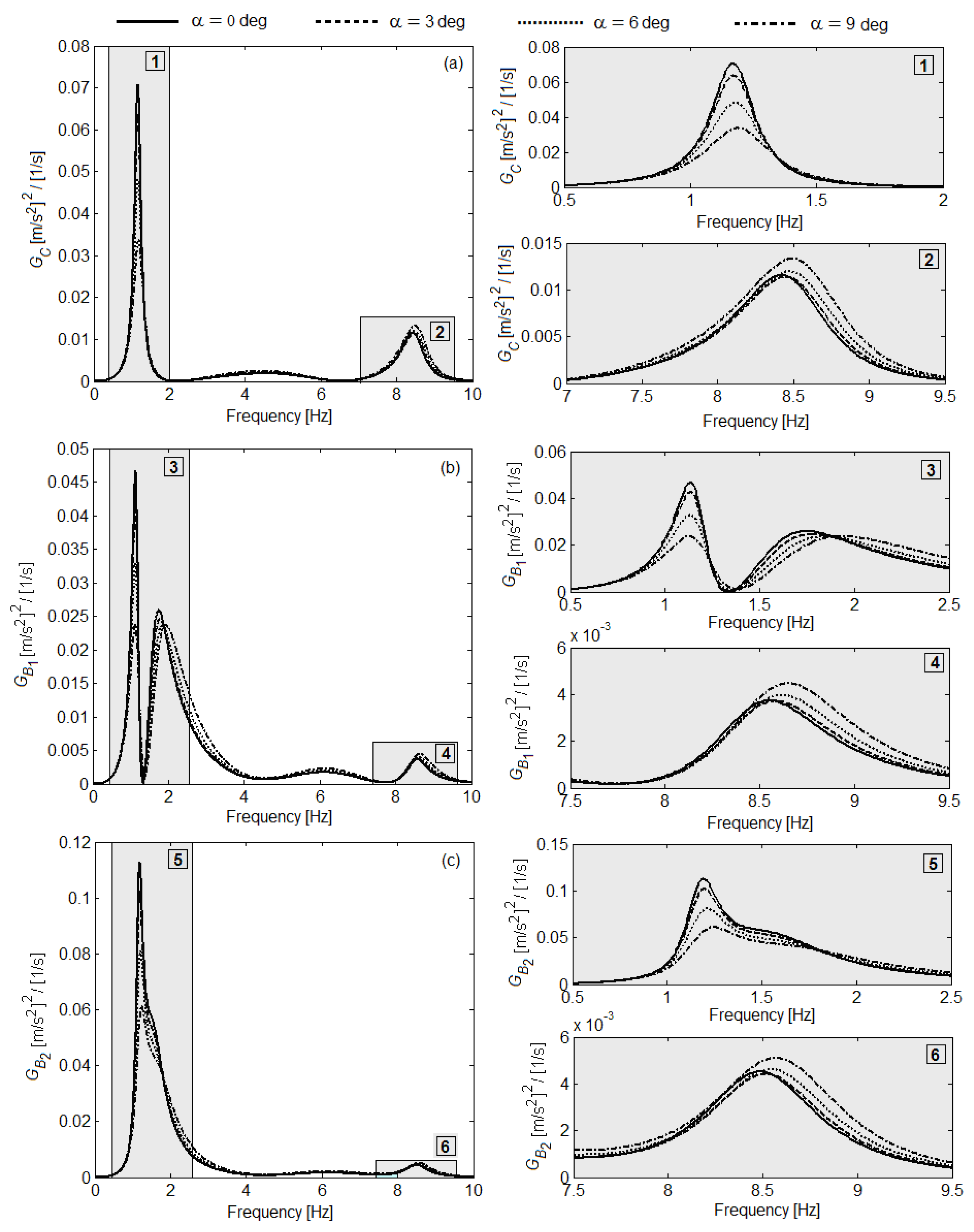
Figure 9 shows the influence of the mounting angle for the anti-yaw damper upon the power spectral density of the acceleration in the carbody reference points. The results presented herein are calculated for k = 107 N/m and c = 5·105 Ns/m. They show the amplification of the vibrations regime at the carbody bending frequency and the reduction of the bounce and pitch carbody vibrations, due to the increase in the mounting angle of the anti-yaw damper.
Figure 10, Figure 11 and Figure 12 highlight the influence of damping and the anti-yaw stiffness upon the ride comfort index in the carbody reference points, in correlation with the vehicle velocity. The results are obtained for α = 10 degrees. First, the ride comfort index is noticed not to be continually increasing along with the velocity, due to the geometric filtering effect given by the vehicle wheelbases. The geometric filtering effect of the track-triggered excitations represents an important characteristic of the vertical vibrations of the railway vehicles, extensively analyzed in many papers [9,11,50,51,52,53,54,55].Due to this effect, sudden decreases of the ride comfort index occur at certain velocities, called geometric filtering velocities [54]. The geometric filtering effect has a selective nature depending on the velocity, with a higher efficiency at velocities smaller than 120 km/h. The geometric filtering manifests more visibly at the carbody center, where the effect comes from both the vehicle wheelbase and the bogie wheelbase. In the carbody reference points against the two bogies, the geometric filtering effect is less efficient, asit only comes from the bogie wheelbase.
As for the influence of the anti-yaw damper upon the ride comfort, except for some limited velocity intervals, a reduction in the ride comfort indices is noticed in all the carbody reference points, and that the reduction becomes more important with the increase in the stiffness of the anti-yaw damper. For instance, Figure 13 shows the percentage values of the decrease in the ride comfort indices in the carbody reference points for k = 5·107 N/m and the three values of the anti-yaw damping. This reduction in the ride comfort index can reach up to 35–40%, depending on velocity and the damping value.
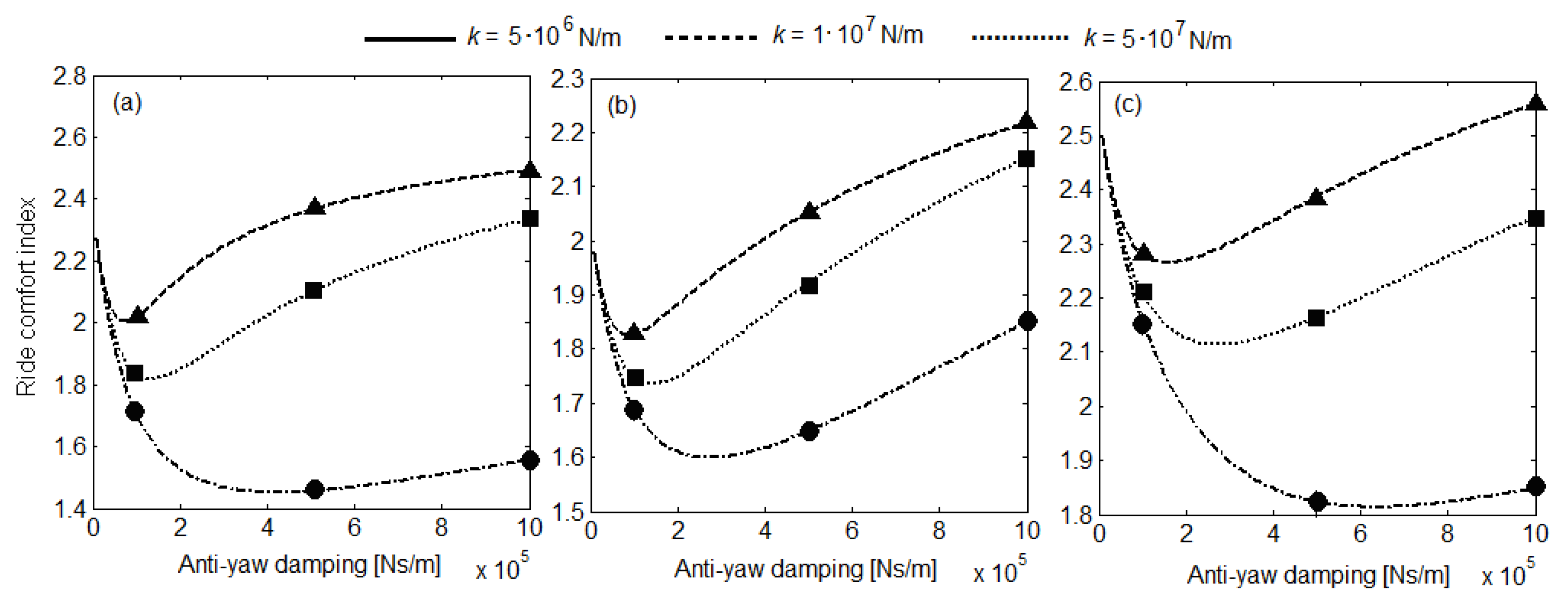
The influence of the anti-yaw damping upon the ride comfort index has to be examined in correlation with the value of the anti-yaw damper stiffness. The diagrams in Figure 14 show that, for the velocity of 300 km/h, the lowest value of the ride comfort index in all the carbody reference points is obtained for k = 5·107 N/m and c = 5·105 kNs/m. Should the stiffness of the anti-yaw damper is smaller (k = 5·106 N/m or k = 1·107 N/m), the lowest value of the ride comfort index is obtained for c = 1·105 kNs/m.
The diagrams in Figure 14 also show that there is an anti-yaw-damping value for which minimum values of the comfort index are obtained. This value depends on the anti-yaw damper stiffness and the position of the carbody reference point (see Table 3).
The influence of the mounting angle for the anti-yaw damper, correlated with the vehicle velocity, upon the ride comfort index is featured in Figure 15, as the percentage increase/decrease of the ride comfort indices. The results are obtained for k = 107 N/m, considering the rise of the angle α from 0 to 10 degrees. As a function of velocity, the carbody reference point and the anti-yaw damping, the increase in the mounting angle has opposite effects on the ride comfort index. The decrease in the ride comfort index, which means the improvement in the ride comfort, is obtained for a large velocity interval for c = 105 Ns/m (diagram a). In this case, this decrease is moderate, of a maximum of 6%. It is observed that the decrease of ride comfort index is higher at the increase in the anti-yaw damping, reaching 15–20%, but the velocity interval narrows down a great deal (diagrams b and c); the ride comfort improves only for the low velocities, of up to 100 km/h.

7. Conclusions

The paper analyzes how the anti-yaw damper affects the vibration behaviour of the railway vehicle carbody and the ride comfort, based on the results derived from numerical simulations. The characteristics of the vertical vibration behaviour of the vehicle carbody are analyzedbased on the results concerning the power spectral density of the vertical acceleration in three carbody reference points, located at the carbody centre and against the bogies. To evaluate the ride comfort at vertical vibrations, the ride comfort index is used, in the same carbody reference points.
The effect of the anti-yaw damper upon the vertical vibration behaviour of the vehicle carbody is highlighted through the increase of the eigenfrequencies of the carbody vibration modes—bounce, pitch and bending.This increase comes from the anti-yaw damping and is more or less visible depending on the value of the anti-yaw damper stiffness. On the other hand, the anti-yaw damper has the effect of reducing the carbody vertical vibrations at the resonance frequencies of the three vibration modes. The decrease of the carbody vibrations is all the more efficient the higher the stiffness of the anti-yaw damper and the value of the anti-yaw damping minimize the power spectral density of the carbody acceleration. The mounting angle of the anti-yaw damper also affects the vertical vibrations behaviour of the carbody, highlighted through the amplification of the bending vibrations and the reduction of the bounce and pitch vibrations.
The effect of the anti-yaw damper upon the ride comfort depends on the vehicle velocity, the damping and stiffness of the anti-yaw damper. The results concerning the ride comfort indices as a function of the damping and stiffness of the anti-yaw damper have shown that the ride comfort indices decrease in all the carbody reference points, except for narrow short velocity intervals, which means an improvement in the ride comfort. The reduction in the ride comfort indices is more important for high values of the anti-yaw damper stiffness, as it can reach up to 35–40%, depending on velocity and the damping value.It was highlighted that is a value of the anti-yaw damping for which minimum values of the ride comfort are obtained, and that this value is correlated with the anti-yaw damper stiffness and the vehicle velocity.
The analysis regarding the increase and the decrease in the ride comfort index due to the mounting angle of the anti-yaw damper is correlated with the anti-yaw damping and the vehicle velocity. The rise in the mounting angle leads to an improvement in the ride comfort on a high velocities range for low values of the anti-yaw damping, yet this improvement is moderate. High values of the anti-yaw damping trigger more visible improvement in the ride comfort on low velocities interval, whereas the ride comfort significantly deteriorates in the high velocities interval.

Author Contributions

Conceptual approach, M.D.; Methodology, M.D.; Software, M.D. and D.I.S.; Validation, M.D.; Formal analysis, M.D. and D.I.S.; Writing—original draft, M.D.; Writing—review and editing, D.I.S. All authors have read and agreed to the publishedversion of the manuscript.

Funding

This research received no external funding.

Conflicts of Interest

The authors declare no conflict of interest.

References

  1. Kim, Y.-G.; Kwon, H.-B.; Kim, S.-W.; Kim, C.-K.; Kim, T.-W. Correlation of ride comfort evaluation methods for railway vehicles. Proc. Inst. Mech. Eng. Part F J. Rail Rapid Transit 2003, 217, 73–88. [Google Scholar] [CrossRef]
  2. Kim, Y.G.; Choi, S.; Kim, S.-W.; Kim, Y.-M.; Park, T.W. An Experimental Study on the Ride Comfort of the Korean High-Speed Train. Exp. Tech. 2009, 33, 30–37. [Google Scholar] [CrossRef]
  3. Kardas-Cinal, E. Ride comfort for various passenger positions in a railway vehicle—Simulation study. Arch. Transp. 2010, 22, 189–199. [Google Scholar] [CrossRef]
  4. Mansfield, N.J. Human Response to Vibration; 2005. Available online: https://docs.wind-watch.org/Mansfield-human-response-vibration.pdf (accessed on 17 November 2020).
  5. Griffin, M. Handbook of Human Vibration; Elsevier BV: Amsterdam, The Netherlands, 1990. [Google Scholar]
  6. Nakagawa, C.; Suzuki, H. Effects of Train Vibrations on Passenger PC Use. Q. Rep. RTRI 2005, 46, 200–205. [Google Scholar] [CrossRef] [Green Version]
  7. Suzuki, H. Effects of the range and frequency of vibrations on the momentary riding comfort evaluation of a railway vehicle. Jpn. Psychol. Res. 1998, 40, 156–165. [Google Scholar] [CrossRef]
  8. Munawir, T.I.T.; Abu Samah, A.A.; Rosle, M.A.A.; Azlis-Sani, J.; Hasnan, K.; Sabri, S.; Ismail, S.; Yunos, M.N.A.M.; Bin, T.Y. A Comparison Study on the Assessment of Ride Comfort for LRT Passengers. IOP Conf. Ser. Mater. Sci. Eng. 2017, 226, 012039. [Google Scholar] [CrossRef] [Green Version]
  9. Cheli, F.; Corradi, R. On rail vehicle vibrations induced by track unevenness: Analysis of the excitation mechanism. J. Sound Vib. 2011, 330, 3744–3765. [Google Scholar] [CrossRef]
  10. Young, T.; Li, C. Vertical Vibration Analysis of Vehicle/Imperfect Track Systems. Veh. Syst. Dyn. 2003, 40, 329–349. [Google Scholar] [CrossRef]
  11. Dumitriu, M. Analysis of the Dynamic Response in the Railway Vehicles to the Track Vertical Irregularities. Part I: The Theoretical Model and the Vehicle Response Functions. J. Eng. Sci. Technol. Rev. 2015, 8, 24–31. [Google Scholar] [CrossRef]
  12. Mazilu, T. Analysis of infinite structure response due to moving wheel in the presence of irregularities via Green’s functions method. Proc. Rom. Acad. Ser. A Math. Phys. Tech. Sci. Inf. Sci. 2009, 10, 139–150. [Google Scholar]
  13. Mazilu, T. Green’s functions for analysis of dynamic response of wheel/rail to vertical excitation. J. Sound Vib. 2007, 306, 31–58. [Google Scholar] [CrossRef]
  14. Pombo, J.; Ambrósio, J. An alternative method to include track irregularities in railway vehicle dynamic analyses. Nonlinear Dyn. 2011, 68, 161–176. [Google Scholar] [CrossRef]
  15. Orvanäs, A. Methods for Reducing Vertical Carbody Vibrations of a Rail Vehicle. Report in Railway Technology Stockholm; KTH Engineering Sciences Department of Aeronautical and Vehicle Engineering, Division of Rail Vehicles: Stockholm, Sweden, 2010. [Google Scholar]
  16. Takigami, T.; Tomioka, T. Investigation to Suppress Bending Vibration of Railway Vehicle Carbodies using Piezoelectric Elements. Q. Rep. RTRI 2005, 46, 225–230. [Google Scholar] [CrossRef] [Green Version]
  17. Kamada, T.; Kiuchi, R.; Nagai, M. Suppression of railway vehicle vibration by shunt damping using stack type piezoelectric transducers. Veh. Syst. Dyn. 2008, 46, 561–570. [Google Scholar] [CrossRef]
  18. Kamada, T.; Hiraizumi, K.; Nagai, M. Active vibration suppression of lightweight railway vehicle body by combined use of piezoelectric actuators and linear actuators. Veh. Syst. Dyn. 2010, 48, 73–87. [Google Scholar] [CrossRef]
  19. Tomioka, T.; Takigami, T. Reduction of bending vibration in railway vehicle carbodies using carbody–bogie dynamic interaction. Veh. Syst. Dyn. 2010, 48, 467–486. [Google Scholar] [CrossRef]
  20. Sugahara, Y.; Watanabe, N.; Takigami, T.; Koganei, R. Vertical vibration suppression system for railway vehicles based on primary suspension damping control—system development and vehicle running test results. Q. Rep. RTRI 2011, 52, 13–19. [Google Scholar] [CrossRef]
  21. Tomioka, T. Reduction of car body elastic vibration using high-damping elastic supports for under-floor equipment. Railw. Technol. Avalanche 2012, 41, 245–270. [Google Scholar]
  22. Aida, K.-I.; Tomioka, T.; Takigami, T.; Akiyama, Y.; Sato, H. Reduction of Carbody Flexural Vibration by the High-damping Elastic Support of Under-floor Equipment. Q. Rep. RTRI 2015, 56, 262–267. [Google Scholar] [CrossRef] [Green Version]
  23. Dumitriu, M. A new passive approach to reducing the carbody vertical bending vibration of railway vehicles. Veh. Syst. Dyn. 2017, 55, 1787–1806. [Google Scholar] [CrossRef]
  24. Dumitriu, M.; Cruceanu, C. Approaches for reducing structural vibration of the carbody railway vehicles. In Proceedings of the 21st Innovative Manufacturing Engineering & Energy International Conference (IManE&E 2017), Iaşi, Romania, 24–27 May 2017; Volume 112, p. 07006. Available online: https://www.matec-conferences.org/articles/matecconf/abs/2017/26/matecconf_imane2017_07006/matecconf_imane2017_07006.html (accessed on 17 November 2020).
  25. Gong, D.; Zhou, J.; Sun, W.; Sun, Y.; Xia, Z. Method of multi-mode vibration control for the carbody of high-speed electric multiple unit trains. J. Sound Vib. 2017, 409, 94–111. [Google Scholar] [CrossRef]
  26. Gong, D.; Zhou, J.; Sun, W. Passive control of railway vehicle car body flexural vibration by means of under frame dampers. J. Mech. Sci. Technol. 2017, 31, 555–564. [Google Scholar] [CrossRef]
  27. Schandl, G.; Lugner, P.; Benatzky, C.; Kozek, M.; Stribersky, A. Comfort enhancement by an active vibration reduction system for a flexible railway car body. Veh. Syst. Dyn. 2007, 45, 835–847. [Google Scholar] [CrossRef]
  28. Dumitriu, M. Ride comfort enhancement in railway vehicle by the reduction of the carbody structural flexural vibration. IOP Conf. Ser. Mater. Sci. Eng. 2017, 227, 012042. Available online: https://iopscience.iop.org/article/10.1088/1757-899X/227/1/012042 (accessed on 17 November 2020). [CrossRef] [Green Version]
  29. Dumitriu, M. Study on Improving the Ride Comfort in Railway Vehicles Using Anti-Bending Dampers. Appl. Mech. Mater. 2018, 880, 207–212. [Google Scholar] [CrossRef]
  30. Dumitriu, M.; Stănică, D.I. An approach to improving the ride comfort of the railway vehicles. UPB Sci. Bull. Ser. D Mech. Eng. 2020, 82, 81–98. [Google Scholar]
  31. Tomioka, T.; Takigami, T.; Suzuki, Y. Numerical analysis of three-dimensional flexural vibration of railway vehicle car body. Veh. Syst. Dyn. 2006, 44, 272–285. [Google Scholar] [CrossRef]
  32. Huang, C.; Zeng, J.; Luo, G.; Shi, H. Numerical and experimental studies on the car body flexible vibration reduction due to the effect of car body-mounted equipment. Proc. Inst. Mech. Eng. Part F J. Rail Rapid Transit 2016, 232, 103–120. [Google Scholar] [CrossRef] [Green Version]
  33. Diana, G.; Cheli, F.; Collina, A.; Corradi, R.; Melzi, S. The Development of a Numerical Model for Railway Vehicles Comfort Assessment Through Comparison With Experimental Measurements. Veh. Syst. Dyn. 2002, 38, 165–183. [Google Scholar] [CrossRef]
  34. Dumitriu, M. On the Critical Points of Vertical Vibration in a Railway Vehicle. Arch. Mech. Eng. 2014, 61, 609–625. [Google Scholar] [CrossRef]
  35. Dumitriu, M.; Crăciun, C. Modelling of structural flexibility of the carbody railway vehicles. In Proceedings of the MATEC Web of Conferences—21st Innovative Manufacturing Engineering & Energy International Conference, Iasi, Romania, 24–27 May 2017; Volume 112, p. 07007. [Google Scholar]
  36. Yang, G.; Wang, C.; Xiang, F.; Xiao, S. Effect of train carbody’s parameters on vertical bending stiffness performance. Chin. J. Mech. Eng. 2016, 29, 1120–1127. [Google Scholar] [CrossRef]
  37. Shi, H.; Wu, P. Flexible vibration analysis for car body of high-speed EMU. J. Mech. Sci. Technol. 2016, 30, 55–66. [Google Scholar] [CrossRef]
  38. Dumitriu, M.; I Stănică, D. Vertical bending vibration analysis of the car body of railway vehicle. IOP Conf. Ser. Mater. Sci. Eng. 2019, 564, 012104. [Google Scholar] [CrossRef]
  39. Dumitriu, M.; Cruceanu, C. Influences of Carbody Vertical Flexibility on Ride Comfort of Railway Vehicles. Arch. Mech. Eng. 2017, 64, 219–238. [Google Scholar] [CrossRef]
  40. Dumitriu, M.; Stănică, D.I. Influence of the Primary Suspension Damping on the Ride Comfort in the Railway Vehicles. Mater. Sci. Forum 2019, 957, 53–62. [Google Scholar] [CrossRef]
  41. Huang, L.; Zeng, J.; Zhou, X.; Song, Y. Mechanical model of yaw damper and its application in the simulation of vehicle system dynamics. IOP Conf. Ser. Mater. Sci. Eng. 2018, 397, 012051. [Google Scholar] [CrossRef] [Green Version]
  42. Yang, D.; Chi, M.; Cai, W.; Wang, X. Study on Piecewise Linear Model of Anti-yaw Damper and Test Analysis. In Proceedings of the 2015 International Industrial Informatics and Computer Engineering Conference, Xi’an, China, 10–11 January 2015; pp. 1179–1189. [Google Scholar]
  43. Mazilu, T. An analysis of bogie hunting instability. UPB Sci. Bull. Ser. D Mech. Eng. 2009, 71, 63–78. [Google Scholar]
  44. Aida, K.-I.; Akiyama, Y.; Nakajima, D.; Tanaka, T.; Takigami, T.; Tomioka, T.; Miyamoto, T.; Nishiyama, Y.; Imaoka, N. Influence of yaw dampers on vertical vibration of railway vehicle carbody and verification of effect by the new mounting structure of yaw damper. In Proceedings of the Transportation and Logistics Conference; Japan Society of Mechanical Engineers: Tokyo, Japan, 2017; p. 3102. [Google Scholar]
  45. Nakajima, D.; Aida, K.-I.; Akiyama, Y.; Takigami, T.; Tomioka, T.; Nishiyama, Y.; Tanaka, T.; Miyamoto, T.; Imaoka, N. Development of a new mounting structure of yaw damper to reduce railway carbody vibration. Trans. JSME 2017, 83, 17-00078. (In Japanese) [Google Scholar] [CrossRef] [Green Version]
  46. I Stanica, D.; Dumitriu, M. Critical points numerical analysis of ride comfort of the flexible railway carbody. IOP Conf. Ser. Mater. Sci. Eng. 2019, 682, 012004. [Google Scholar] [CrossRef]
  47. C 116. Interaction between Vehicles and Track, RP 1, Power Spectral Density of Track Irregularities, Part 1: Definitions, Conventions and Available Data; UIC: Utrecht, The Netherlands, 1971. [Google Scholar]
  48. UIC 513R. Guidelines for Evaluating Passenger Comfort In Relation to Vibration in Railway Vehicles; International Union of Railways: Paris, France, 1994. [Google Scholar]
  49. EN 12299. Railway Applications. Ride Comfort for Passengers. Measurement and Evaluation; British Standard: London, UK, 1999. [Google Scholar]
  50. Zhou, J.; Wenjing, S. Analysis on geometric filtering phenomenon and flexible car body resonant vibration of railway vehicles. J. Tongji Univ. Nat. Sci. 2009, 37, 1653–1657. [Google Scholar]
  51. Zhou, J.; Goodall, R.; Ren, L.; Zhang, H. Influences of car body vertical flexibility on ride quality of passenger railway vehicles. Proc. Inst. Mech. Eng. Part F J. Rail Rapid Transit 2009, 223, 461–471. [Google Scholar] [CrossRef] [Green Version]
  52. Gong, D.; Gu, Y.J.; Zhou, J.S. Study on Geometry Filtering Phenomenon and Flexible Car Body Resonant Vibration of Articulated Trains. Adv. Mater. Res. 2013, 787, 542–547. [Google Scholar] [CrossRef]
  53. Gong, D.; Zhou, J.; Sun, W.-J. On the resonant vibration of a flexible railway car body and its suppression with a dynamic vibration absorber. J. Vib. Control. 2012, 19, 649–657. [Google Scholar] [CrossRef]
  54. Dumitriu, M. Analysis of the dynamic response in the railway vehicles to the track vertical irregularities. Part II: The numerical analysis. J. Eng. Sci. Technol. Rev. 2015, 8, 32–39. [Google Scholar] [CrossRef]
  55. Wu, J.; Qiu, Y. Analysis of ride comfort of high-speed train based on a train-seat-human model in the vertical direction. Veh. Syst. Dyn. 2020, 1–27. [Google Scholar] [CrossRef]
Figure 1. The mechanical model of the railway vehicle.
Applsci 10 08167 g001
Figure 2. Forces acting upon the carbody.
Applsci 10 08167 g002
Figure 3. Influence of the damping and the anti-yaw damper stiffness upon the power spectral density of the carbody acceleration at the carbody center.
Applsci 10 08167 g003
Figure 4. Influence of the damping and the anti-yaw damper stiffness upon the power spectral density of the carbodyaccelerationagainst the front bogie.
Applsci 10 08167 g004
Figure 5. Influence of the damping and the anti-yaw damper stiffness upon the power spectral density of the carbodyaccelerationagainst the rear bogie.
Applsci 10 08167 g005
Figure 6. Influence of the damping and the anti-yaw damper stiffness upon the carbody eigenfrequencies: (a) bounce eigenfrequency; (b) pitch eigenfrequency; (c) bending eigenfrequency.
Applsci 10 08167 g006
Figure 7. Influence of the anti-yaw damper stiffness upon the power spectral density of the carbody acceleration: (a) at the carbody center; (b) against the front bogie; (c) against the rear bogie.
Applsci 10 08167 g007
Figure 8. Influence of the anti-yaw damping upon the power spectral density of the carbody acceleration: (a) at the carbody center; (b) against the front bogie; (c) against the rear bogie.
Applsci 10 08167 g008
Figure 9. Influence of the mounting angle of the anti-yaw damper upon the power spectral density of the carbody acceleration: (a) at the carbody center; (b) against the front bogie; (c) against the rear bogie.
Applsci 10 08167 g009
Figure 10. Influence of damping and stiffness of the anti-yaw damper upon the ride comfort index at the carbody center.
Applsci 10 08167 g010
Figure 11. Influence of damping and stiffness of the anti-yaw damper upon the ride comfort index in the front bogie.
Applsci 10 08167 g011
Figure 12. Influence of damping and stiffness of the anti-yaw damper upon the ride comfort index in the rear bogie.
Applsci 10 08167 g012
Figure 13. Reduction of the ride comfort indices for k = 5·107 N/m: (a) at the carbody center; (b) against the front bogie; (c) against the rear bogie.
Applsci 10 08167 g013
Figure 14. Influence of the anti-yaw damping upon the ride comfort index at a velocity of 300 km/h: (a) at carbody center; (b) against the front bogie; (c) against the rear bogie.
Applsci 10 08167 g014
Figure 15. Influence of the increase in the mounting angle of the anti-yaw damper upon the ride comfort index: (a) c = 1·105 Ns/m; (b) c = 5·105 Ns/m; (c) c = 1·106 Ns/m.
Applsci 10 08167 g015
Table 1. The significance of the ride comfort index NMV.
Ride Comfort Index NMVSignificance
NMV < 1Very comfortable
1 ≤ NMV < 2Comfortable
2 ≤ NMV< 4Medium
4 ≤ NMV < 5Uncomfortable
NMV ≥ 5Very uncomfortable
Table 2. Reference parameters of the vehicle model.
mc = 34,000 kg2kzc = 1.2 MN/m
mb = 3200 kg2czc = 34.28 kNs/m
Jc = 1,963,840 kg·m24kzb = 4.4 MN/m
Jb = 2048 kg·m24czb = 52.21 kNs/m
EI = 3.158·109 Nm2Lc = 26.4 m
mmc = 35,224 kg2ac = 19 m; 2ab = 2.56 m
kmc = 88.998 MN/mh = 1.6 m
cmc = 53.117 kNm/sb = 1 m
Table 3. The anti-yaw damping values to minimize the ride comfort index at 300 km/h.
k [N/m]At Carbody CenterAgainst the Front BogieAgainst the Rear Bogie
c [Ns/m] N M V C min   c [Ns/m] N M V B 1 min c [Ns/m] N M V B 2 min
5·1060.7·1052.000.9·1051.831.6·1052.26
1·1071.3·1051.821.4·1051.742.7·1052.11
5·1074.2·1051.452.7·1051.606.3·1051.81
Publisher’s Note: MDPI stays neutral with regard to jurisdictional claims in published maps and institutional affiliations.