Article

An Automatic Optimized Method for a Digital Optical Phase Conjugation System in Focusing through Scattering Media

1
Key Laboratory of High Power Laser and Physics, Shanghai Institute of Optics and Fine Mechanics, Chinese Academy of Sciences, Shanghai 201800, China
2
Center of Materials Science and Optoelectronics Engineering, University of Chinese Academy of Sciences, Beijing 100049, China
*
Author to whom correspondence should be addressed.
Appl. Sci. 2020, 10(23), 8321; https://doi.org/10.3390/app10238321
Submission received: 19 October 2020 / Revised: 23 November 2020 / Accepted: 23 November 2020 / Published: 24 November 2020
(This article belongs to the Special Issue Laser Spectroscopy)

Abstract

:

Featured Application

Digital optical phase conjugation (DOPC) is an effective method to suppress the scattering effect and achieve focusing and imaging through scattering media. However, the practical implementation and quality of DOPC are greatly limited by imperfect pixel alignment, optical aberration, and mechanical error in a DOPC system. Based on the multipopulation genetic algorithm, an automatic optimized method for a DOPC system is propose to comprehensively solve the above problems represented by Zernike polynomials and improve the compensation quality of DOPC. This work can be helpful to promote the practical uses of the DOPC system.

Abstract

In this paper, a reliable automatic optimized method for a digital optical phase conjugation (DOPC) system based on a multipopulation genetic algorithm (MPGA) is proposed for improving the compensation quality of DOPC. The practical implementation and compensation quality of DOPC in focusing through scattering media are greatly limited by imperfect pixel alignment, optical aberration, and mechanical error in the DOPC system. For comprehensively solving the above problems, the concept of global optimization is introduced by Zernike polynomials (Zernike modes) to characterize overall imperfections, and MPGA is used to search for the most optimal Zernike coefficient and compensate for the overall imperfections of the DOPC system. The significant optimization ability of the proposed method is verified in DOPC-related experiments for focusing through scattering media. The peak-to-background ratio (PBR) of the OPC focus increases 174 times that of the initial OPC focus. Furthermore, we evaluated the optimization results of the proposed method with a fitness function of intensity fitness and correlation coefficient fitness in MPGA. The results show that the optimized capability is excellent and more efficiently used than the correlation coefficient fitness function in the Zernike modes.

1. Introduction

Focusing and imaging through scattering media are of uttermost importance in bioimaging [1,2,3,4,5,6,7,8] and measurements [9]. In scattering media, the extensive scattering of light is a significant obstacle for optical focusing and imaging [10]. For suppression of the scattering effect, various methods have been proposed and have achieved excellent compensation effects, such as modulating wavefront with transmission matrix measurement [11,12,13], iterative wavefront optimization [14,15], and optical phase conjugation (OPC) [16,17,18]. However, the transmission matrix measurement requires massive data collection [13]. Additionally, time-consuming iterations are required for the compensation effect in iterative wavefront optimizations. Among these methods, OPC [19], with its time-reversal nature, can undo the effects of multiple scattering in scattering media without time-consuming iterations. Therefore, employing OPC to suppress scattering media is appealing, which simply requires the duplication of a transmission light field to make the phase at each point on the wavefront sign-reversed. OPC has been of interest in many fields, including wavefront shaping [20,21], images through scattering media [22,23], and high-resolution imaging [24,25]. Generally, a phase-conjugate beam is generated by the analog OPC technique [26,27,28] and digital OPC (DOPC) [29,30,31,32,33]. In the analog OPC technique, the lack of freedom to manipulate the recorded hologram pattern and the phase-conjugated light results in restrictions in many biomedical applications. Therefore, DOPC can be the proper way to generate the phase conjugate for several intrinsic advantages, including higher phase conjugate reflectivity and a flexibly adjustable phase conjugate wavefront.
DOPC consists of a charge-coupled device (i.e., CCD) and a spatial light modulator (SLM) to achieve recording and wavefront playback. Although straightforward in principle, the practical implementation and utility of DOPC are limited by the imperfections of the system in a complicated and coupled way. The optimal performance and compensation quality of a DOPC system are demanding for exact pixel-to-pixel alignment, which greatly restricts the actual compensation quality [22]. Pixel misalignment consists of two parts: pixel misalignment between SLM and CCD, and pixel misalignment between object light and conjugate light on the surface of the scattering medium. These problems can result in poor compensation effects in experiments. Generally, one direct method to eliminate pixel misalignment is to alter the misalignment parameters Δx, Δy, and Δz (misalignment parameters in the three displacement axes proposed in [32]) are defined as Δ-xyz modes in this paper for simplicity. Unfortunately, it can greatly solve issues of pixel misalignment but has no significant effect on mechanical errors and optical aberrations that are mainly caused by optical elements, light sources, and surface profiles of SLM. The optical aberration in a DOPC system, such as astigmatism, and coma, can hinder the quality of the DOPC system. Therefore, for further improving the compensation effect, we used coefficients of 1st to 8th Zernike polynomials [34,35] as optimization variables, called Zernike modes here, to characterize both misalignments in Δ-xyz modes and other imperfections of the DOPC system. Zernike polynomials with higher orders are found to have less influence on DOPC [34]. Compared with Δ-xyz modes, Zernike modes [34] not only have a two-dimensional translation function but can also compensate for higher-order aberrations, including curvature of SLM and other optical aberrations in the DOPC system. In order to obtain the optimal compensation effect and improve the quality of DOPC, it is necessary to seek an efficient and accurate algorithm to acquire the optimal Zernike coefficients. Among the optimization algorithms, the multipopulation genetic algorithm (MPGA) [36,37,38] can be the proper algorithm to combine with DOPC for its intrinsic advantages, including the small amount of computation, strong convergence, and excellent real-time performance, especially in solving global optimization problems. Furthermore, the fitness function of the algorithm is crucial to the optimization result by MPGA. Considering this, we used different correlation coefficient fitness functions in MPGA and evaluated the optimization results.
In this paper, a reliable automatic optimized method for a DOPC system is proposed based on a multipopulation genetic algorithm (MPGA) for improving the compensation quality of DOPC. This method improves the compensation quality of DOPC by compensating for the overall imperfections characterized by Zernike polynomials. MPGA is used to search for the optimal Zernike coefficients by correlation coefficient fitness in order to obtain the optimal phase in the DOPC system. The significant optimization ability of the proposed method is verified in DOPC-related experiments for focusing through scattering media.

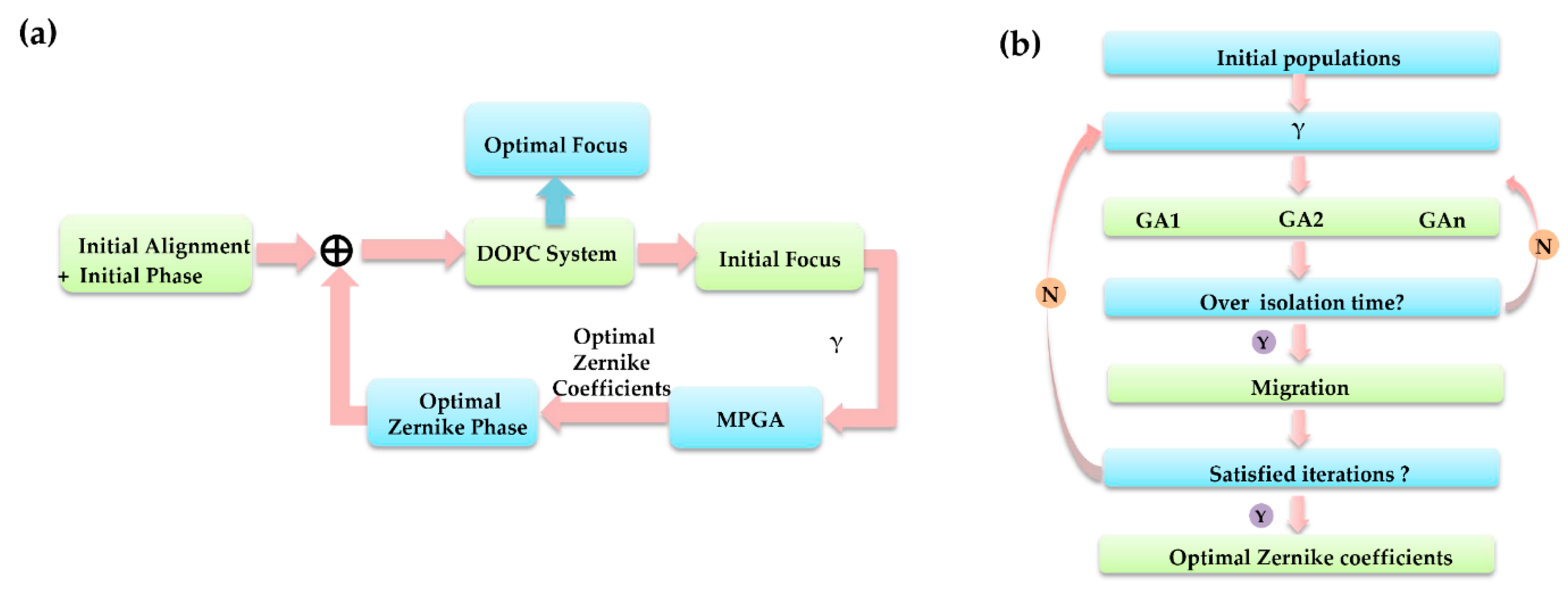
2. Method for Automatic Optimization of the DOPC System

Digital optical phase conjugation (DOPC) is known to be able to time-reverse the scattering process and compensate for wavefront distortions. In the absence of absorption, the time-reversal signal can be explained with the reciprocity theorem [7,39] in the spatial frequency domain, assuming the initial input field is E 1 ( k x , k y ) . After transmission through the scattering medium and the optical system, the initial output field E 2 ( k x , k y ) can be written as
E 2 ( k x , k y ) = E 1 ( k x , k y ) H ( k x , k y , k x , k y ) d k x d k y ,
where H ( k x , k y , k x , k y ) is a transfer function from the input mode ( k x , k y ) to the transmission mode ( k x , k y ) . E 2 ( k x , k y ) interferes with the reference beam and the interference pattern is recorded by CCD, from which the conjugate phase φ 0 is obtained. After adding it to the SLM, the conjugate beam E 2 ( k x , k y ) is propagated back to the transmission through scattering medium and the optical system; the field can be written as
E 1 ( k x , k y ) = E 2 ( k x , k y ) H ( k x , k y , k x , k y ) d k x d k y ,
where H ( k x , k y , k x , k y ) is a transfer function from the input mode ( k x , k y ) to the transmission mode ( k x , k y ) . According to the reciprocity theorem, for stationary media, it can be known that H ( k x , k y , k x , k y ) = H ( k x , k y , k x , k y ) . As a result of Equations (1) and (2), it is concluded that E 1 ( k x , k y ) = E 1 ( k x , k y ) in an ideal situation of DOPC, where * denotes a conjugated phase. The direction of E 1 is opposite to that of E 1 . However, it is not exactly equal in practical experiments because the actual compensation quality of DOPC is limited by pixel alignments, optical aberrations, and mechanical errors of the DOPC system. By focusing through a scattering medium, the focal spot obtained by DOPC compensation is not equal to the target focus without a scattering medium. For comprehensively solving the above problems and further improving the compensation effect, we introduce Zernike modes characterized by Zernike polynomials to compensate for the overall imperfections in the DOPC system. Here, we assume the amplitude of plane wave E 2 ( k x , k y ) is 1, and its conjugate phase φ 0 is obtained by phase shift holography [40]. With Zernike modes, the optimal compensation phase φ 0 + φ z e r n i k e is added into the SLM after reverse transmission through a scattering medium; the optimized field E 1 ( k x , k y ) can be written as Equation (3). Additionally, the final optimized focused field E f 1 ( k x , k y ) can be written as Equation (4).
E 1 ( k x , k y ) = exp [ i ( φ 0 + φ z e r n i k e ) ] H ( k x , k y , k x , k y ) d k x d k y ,
E f 1 ( k x , k y ) = E 1 ( k x , k y ) H L ( k x , k y ) ,
where H L ( k x , k y ) is the Fourier change of the lens factor, represents convolution; H ( k x , k y , k x , k y ) is a transfer function from the input mode ( k x , k y ) to the transmission mode ( k x , k y ) . E f 1 ( k x , k y ) is the initial ideally focused field without a scattering medium that is used as target-focused field. When the phase conjugation is ideal (i.e., E 1 ( k x , k y ) = E 1 ( k x , k y ) ), then from Equation (4), it is concluded that E f 1 ( k x , k y ) = E f 1 ( k x , k y ) . However, it is not exactly equal in practical experiments. In order to maximize the correlation coefficient between E f 1 ( k x , k y ) and E f 1 ( k x , k y ) , it is necessary to seek an efficient and accurate algorithm for the optimal Zernike coefficients. In this paper, we propose an automatic optimized method for a DOPC system based on a multipopulation genetic algorithm (MPGA). Among algorithms, with the enhancement of computing capability, deep learning has gained more accuracy in image segmentation than traditional segmentation and is widely used in medical image processing [41]. A comparison of fuzzy logic (FL), traditional neural networks (NNs), and genetic algorithms (GAs) in image segmentation has been discussed [42]. As for our experiment, it is difficult to obtain the training set needed for NN training. Additionally, there is no guarantee of a global optimal solution. Therefore, we used MPGA to obtain a faster global optimal solution. Moreover, compared with the traditional single-point search method, MPGA is not limited by the precision of the sampling interval. Additionally, it does not demand balanced sampling accuracy and iteration time, which means it can do a fast search for more accurate optimization parameters.
The flow chart of the automatic optimized method for a DOPC system is outlined in Figure 1a. Taking focusing through scattering media as an example, the optimization process is illustrated as follows. Above all, after the initial pixel alignment in the DOPC system, the initial phase ( φ 0 ) of the scattering media is obtained and loaded into a spatial-light modulator (SLM). After DOPC system, an initial OPC focus is obtained. We start with the focus and the initial phase is used as the current initial state of MPGA. The optimal Zernike coefficients are obtained by MPGA iteration. The optimal Zernike phase generated by the optimal Zernike coefficients is added to the initial phase and then loaded into the SLM. After DOPC system, an optimal focus is eventually obtained.
The flow chart of MPGA is shown in Figure 1b. The initial populations are divided into 8 subpopulations, the number of individuals in each population is 15, and each individual is one vector of Zernike coefficients. After that, the parallel traditional genetic algorithms (GAs) are implemented on each population. Each GA coded by a real number has a 10% mutation rate and a 90% crossover rate. According to the fitness function, information between individuals is constantly exchanged through selection, crossover, and mutation operations to continuously select individuals. Individuals with low fitness values for the environment are eliminated, and the surviving individuals will automatically group into new groups. Additionally, 30% of optimal individuals in each subpopulation are exchanged to form a new population every 20 iterations. Therefore, the migration strategy can accelerate convergence [43]. Through constant updating and iteration, the optimal individual satisfying the fitness function can be finally acquired. The iteration of the algorithm is 100. The iteration time is 1925.7 s, and the single iteration time is about 200 ms, which concludes 150 ms CCD sampling time and 50 ms computing time. It should be emphasized that the theoretical minimum iteration time of this method depends on the SLM refresh frequency, which is 60 Hz, and the iteration time is 16.7 ms. The selection of fitness function is quite important to ensure that the MPGA quickly converges to a global optimum. We introduced the Pearson correlation coefficient (γ) [44,45] as the fitness function, which is written as
γ = k x = 1 P k y = 1 Q [ I f 1 ( k x , k y ) f ¯ ] [ I f 1 ( k x , k y ) w ¯ ] { k x = 1 P k y = 1 Q [ I f 1 ( k x , k y ) f ¯ ] 2 k x = 1 P k y = 1 Q [ I f 1 ( k x , k y ) w ¯ ] 2 } 1 2 ,
where f ¯ = 1 P Q k x = 1 P k y = 1 Q I f 1 ( k x , k y ) , w ¯ = 1 P Q k x = 1 P k y = 1 Q I f ( k x , k y ) . kx and ky denote the coordinates of the image. I f 1 ( k x , k y ) is the intensity of the optimized focused field; I f 1 ( k x , k y ) is the intensity of the target focused field. The Pearson correlation coefficient (γ) is suitable for different complex target patterns and is widely used as any shape of the reference object, especially in the scattering field.

3. Experiment and Discussion

The automatic optimized method for the DOPC system is performed through the following two steps. Step 1: achieve the initial pixel alignment of the DOPC system and obtain the initial phase. Step 2: finish the optimization step based on this method.

3.1. Initial Pixel Alignment of the DOPC System and Initial Conjugate Phase Acquisition

3.1.1. Initial Conjugate Phase Acquisition

The experimental DOPC system is shown in Figure 2. The illumination beam (632.8 nm) was split into two beams by BS1: an object beam and a reference beam. A1 and A2 were used to adjust the interference field to the appropriate intensity. A half-wave plate (H) was used to adjust the polarization to a horizontal direction to ensure the maximum modulation efficiency of the SLM (Holoeye, PLUTO-VIS-016). L2, L3 and L5, L6 are aspherical lenses that were used to expand the reference beam and the object beam to the appropriate size. The diameters were 24 and 4 mm, respectively. In the object beam, a scattering medium (Thorlabs, DG-220) was placed in the back of the microscope objective (MO1, 20X, NA = 0.4), and the scattering field was collected by MO2 (20X, NA = 0.4). The MO3 (20X, NA = 0.4) and the hole were used to expand and filter the object beam. The reference beam passed through a quarter-wave plate to achieve phase shift holography. The scattering field was interfered with by the reference beam by BS3. The SLM plane was directly imaged onto the CCD1 (Teledyne DALSA, G2-GC10-T4095) target by L8. Additionally, the interference intensity on the SLM was recorded by CCD1. Phase measurement of the scattering field was realized by the two-step digital phase shift holography using a quarter-wave plate (Q), and the conjugate phase of the scattering field can be expressed by ([40])
φ 0 = tan 1 [ ( I ( x , y , π 2 ) I r e f I o b j I ( x , y , 0 ) I r e f I o b j ) ] ,
where * represents the complex conjugate. In the playback step, after adding the conjugate phase to the SLM, the conjugate beam propagated to BS2 and was focused. The final focus field was recorded by CCD2 (IMPERX, GEV-B2021M-TF000). Initial pixel alignment of the DOPC system is described in detail in Section 3.1.2.

3.1.2. Initial Pixel Alignment of the DOPC System

The initial phase φ 0 by the two-step digital phase shift holography method has enough precision for compensation. In contrast, pixel misalignment has a greater influence on the experiment. Several pixel misalignments can greatly restrict the final optimization. Thus, it is necessary to carry out the initial pixel alignment of the DOPC system before optimization. In the DOPC system, the optimal performance requires a pixel alignment between object light and conjugate light on the surface of the scattering medium and pixel alignment between the SLM and CCDs. The SLM should be perpendicular to the incident reference beam. The power of the beam, back-propagated through the MO1-3, is measured by a power meter placed between L3 and M2, and the back-propagating signal is maximized by adjusting the rotation platform of the SLM carefully. In such a way, the phase conjugate beam and the object beam are roughly in a total optical path and act at the same position as the scattering medium (SM).
Then, pixel-to-pixel alignment is required between CCD1 and the SLM. The SLM plane is directly imaged on the CCD1 plane via L8. When the pixel dimensions of CCD1 and the SLM are 6 and 8 microns, the pixel-size matching can be addressed by adjusting μ and v based on
μ + ν = f × ( M + 1 ) 2 / M ,
where μ is the length between SLM and L8, ν is the length between CCD1 and L8, f is the focal length of L8 (f = 100 mm), M is equal to the ratio between dCCD1 and dSLM. dCCD1 is the pixel dimensions of CCD1, and dSLM is the pixel dimensions of the SLM.
After that, a phase pattern of a negative United States Air Force (USAF) target was loaded in the SLM, and the corresponding image was obtained by CCD1, as shown in Figure 3a,b. According to the relationship between the pattern and the image, we can determine the pixel correspondence between the SLM and CCD1. We subtracted the inverted image of CCD1 from the pattern loaded by the SLM, as shown in Figure 3c. The magenta part represent s the pattern loaded by SLM, and the green one represent s the inverted image of CCD1. The green and magenta ones should be completely consistent in size and position, which means that the pixel alignment between the SLM and the CCD is achieved. The misalignment of pixels can be greatly eliminated by fine-tuning the pixel correspondence, as shown in Figure 3c,d. In this way, the rough pixel alignment between the SLM and CCD1 was achieved. Additionally, the initial pixel alignment of the DOPC system is finished.

3.2. Focusing through the Scattering Media Based on the Automatic Optimized Method for DOPC System

Based on the automatic optimized method mentioned above, the optimization ability of compensation on OPC focusing was verified, and the experimental results are shown in Figure 4. Figure 4a shows the image by CCD2 when the phase of the SLM was set to 0, which means the DOPC system was not used. At the same time, the conjugate beam propagated back to the transmission through scattering medium was an unmodulated plane wave. After carefully aligning the system conventionally, the initial OPC focus through the SM can be obtained, as shown in Figure 4d. Figure 4g shows the conjugate phase loaded in the SLM. Instead of initiating the MPGA positions completely randomly, here, we designated the initial position as the initial OPC focus. The correlation coefficient was chosen as the fitness function. We compared the compensation effect of only optimizing misalignment parameters Δx, Δy, and Δz (misalignment parameters in the three displacement axes), with Zernike polynomial optimization. Here, the two situations can be simplified and defined as the Δ-xyz modes and Zernike modes, respectively. After the above optimization process by MPGA, the final optimal compensation phase of the two modes loaded into the SLM can be written as
φ o p _ Δ - x y z ( Δ x , Δ y , Δ z ) =   φ 0 + 2 π { [ f x ( x Δ x ) + f y ( y Δ y ) ] + Δ z λ [ 1 ( λ f x ) 2 ( λ f y ) 2 ] } ,
φ o p _ Z e r n i k e ( ρ , θ ) = φ 0 + [ z 1 ρ cos θ + z 2 ρ sin θ + z 3 ( 2 ρ 2 1 ) + z 4 ρ 2 cos 2 θ + z 5 ρ 2 sin 2 θ + z 6 ( 3 ρ 2 1 ) ρ cos θ + z 7 ( 3 ρ 2 1 ) ρ sin θ + z 8 ( 6 ρ 4 6 ρ 2 + 1 ) ] ,
where Δ x , Δ y , Δ z are misalignment parameters in the three displacement axes. f x and f y are spatial frequency; λ is the wavelength; φ 0 is the initial conjugate phase of the scattering field; the origin of ( ρ , θ ) is selected in the center of the SLM panel. z 1 : tilt of X; z 2 : tilt of Y; z 3 : focus; z 4 : focus and astigmatism of 0°; z 5 : focus and astigmatism of 45°; z 6 : coma and tilt of X; z 7 : coma and tilt of Y; z 8 : spherical and focus.
In Δ-xyz mode, the final OPC focus was acquired, as shown in Figure 4e. The peak-to-background ratio (PBR) [31,32] of the OPC focus increased from the original 310 to 16,300, which is defined as the ratio of the peak intensity of the OPC focus to the mean intensity of the speckle pattern when a random phase map is loaded in the SLM. The correlation coefficient is a statistical index used to reflect the degree of correlation between the ideal focus and the OPC focus. The value of γ increased from the original 0.41 to 0.73. In the Zernike modes, after the optimization step was completed, the final OPC focus was acquired, as shown in Figure 4f. The Zernike coefficients of the global compensation phase from the MPGA in this experiment are given in Figure 4b. The PBR of the OPC focus increased from the original 310 to 54,000; it increased 174 times that of the initial OPC focus. It achieved about 3.3 times the enhancement of compensation effect compared with the Δ-xyz modes. The correlation coefficient (γ) with Zernike modes increased from the original 0.41 to 0.78, which has a higher interrelationship than the 0.73 score of the Δ-xyz modes. The line profiles of the central row of the focal spot are shown in Figure 4c; the full width at half maximum (FWHM) of the focal spot decreased from 35.4 to 19.7 μm. It is smaller than the 21.4 μm in the Δ-xyz modes. Comparing Figure 4e,f, it can be concluded that the Zernike modes can not only compensate for the misalignment parameters in the three displacement axes but also suppress the aberration of the system by decreasing the noise around the focal spot. The comparison of optimization abilities under the three methods is shown in Table 1. Obviously, the compensation quality of DOPC is greatly optimized by Zernike modes in the automatic optimized method, which is better than the Δ-xyz modes. Moreover, we use circular polynomials as Zernike modes, which are widely employed in circular pupils. When applying them to a rectangular area, such as the SLM, they might not compensate for the optical aberrations at the corners [46]. Using rectangular polynomials [46,47] might further improve the compensation effect.
For further exploration of the optimized capability of the automatic optimized method, we used intensity fitness as the fitness function of MPGA. Intensity fitness is defined as the comparison between the maximum intensity of the focus and the maximum intensity of the target focus. The results of intensity fitness are compared with Figure 4f, representing the correlation coefficient. During the optimization in the two cases, we recorded the typical normalized intensity and the correlation coefficient curves of the OPC focus with generation, as shown in Figure 5a,b. The normalized intensity is defined as the ratio of peak intensity of the current focal spot and the maximum intensity 65,535, which depends on the bit depth of the camera; it decreased from 0.77 to 0.55, and the correlation coefficient (γ) decreased from 0.78 to 0.68. Figure 5c shows the line profiles of the central row of the focal spot; the FWHM of intensity fitness was about 23.3 μm, which is worse than the FWHM of 19.7 μm in Figure 4f. Additionally, the PBR was about 20,400 with intensity fitness. The comparison of optimization abilities in two fitness functions is shown in Table 2. This method with Zernike modes can raise the correlation coefficient to above 0.7. Thus, for a correlation coefficient of less than 0.7, this method is available for compensation improvement. Moreover, there is no specific relationship between the iteration time and initial input. The misalignment in DOPC has no direct effect on the final iteration time. In summary, it is concluded that the optimized capability of the automatic optimized method for DOPC quality is more obvious when the correlation coefficient (γ) is chosen as a fitness function with the Zernike modes.

4. Conclusions

In conclusion, an automatic optimized method for a DOPC system based on the MPGA has been presented to optimize the compensation quality of DOPC. This method improves the compensation quality of DOPC by compensating the overall phase introduced by the problems of pixel alignment, optical aberration, and mechanical error. For comprehensively solving the above problems, we introduced the concept of global optimization by Zernike polynomials (Zernike modes) to characterize overall imperfections and used the MPGA to search for the optimal Zernike coefficients in the DOPC system. In addition, to clearly characterize the advantages of Zernike modes, we introduced the Δ-xyz modes as optimization parameters for comparison. Experimentally, the PBR of the OPC focus with Zernike modes increased 174 times to that of the original focus, which achieves about 3.3 times the enhancement of compensation effect compared with the Δ-xyz modes. The correlation coefficient increased from the original 0.41 to 0.78, which is better than the 0.73 score of the Δ-xyz modes. Furthermore, we evaluated the optimization results of the proposed method with the fitness functions of intensity fitness and correlation coefficient fitness in the MPGA. The results show that the optimized capability is excellent and the correlation coefficient is more suitable as a fitness function in Zernike modes. Moreover, it should be mentioned that this method only demands a rough initial pixel alignment. In the future, further optimization of the devices is expected to further shorten the optimization time of the algorithm and improve experimental efficiency [48]. For different grit sizes of diffuser media, the smaller grit size introduces larger speckles and output angles [49]. The larger output angle exceeds the collection capacity of the microscope objective. It will reduce the measurement accuracy of scattering wavefronts in the scattering medium and affect the final PBR of DOPC. Therefore, for different grit sizes of diffuser media, it is necessary to use the appropriate microscope objective to collect maximum scattering information. Finally, we hope that this work contributes to the practical uses of the DOPC system.

Author Contributions

D.L. and P.Z. came up with the idea; P.Z. and Z.L. designed the experiment and the software program; P.Z., Z.L., and L.H. performed the experiment; P.Z. analyzed the data and wrote the original manuscript; Z.L., D.L., and J.Z. did the review and editing. All authors have read and agreed to the published version of the manuscript.

Funding

This research was funded by the Shanghai Sailing Program (18YF1425900), the National Natural Science Foundation of China (11774364), the Bureau of International Cooperation, the Chinese Academy of Sciences (181231KYSB20170022), and the Strategic Priority Research Program of Chinese Academy of Sciences Grant No. (XDA25020302).

Conflicts of Interest

The authors declare no conflict of interest.

References

  1. Popoff, S.M.; Lerosey, G.; Fink, M.; Boccara, A.C.; Gigan, S. Image transmission through an opaque material. Nat. Commun. 2009, 1, 81. [Google Scholar] [CrossRef] [PubMed]
  2. Bertolotti, J.; van Putten, E.G.; Blum, C.; Lagendijk, A.; Vos, W.L.; Mosk, A.P. Non-invasive imaging through opaque scattering layers. Nature 2015, 491, 232. [Google Scholar] [CrossRef]
  3. Newman, J.A.; Webb, K.J. Imaging optical fields through heavily scattering media. Phys. Rev. Lett. 2014, 113, 263903. [Google Scholar] [CrossRef]
  4. Sudarsanam, S.; Mathew, J.; Panigrahi, S.; Fade, J.; Alouini, M.; Ramachandran, H. Real-time imaging through strongly scattering media: Seeing through turbid media, instantly. Sci. Rep. 2016, 6, 25033. [Google Scholar] [CrossRef] [PubMed]
  5. Tajahuerce, E.; Durán Vicente Clemente, P.; Irles, E.; Soldevila, F.; Andrés, P.; Lancis, J. Image transmission through dynamic scattering media by single-pixel photodetection. Opt. Express 2014, 22, 16945–16955. [Google Scholar] [CrossRef] [PubMed] [Green Version]
  6. Lochocki, B.; Adrian Gambín Manzanera, S.; Irles, E.; Artal, P. Single pixel camera ophthalmoscope. Optica 2016, 3, 1056–1059. [Google Scholar] [CrossRef]
  7. Cui, M.; Mcdowell, E.J.; Yang, C. An in vivo study of turbidity suppression by optical phase conjugation (TSOPC) on rabbit ear. Opt. Express 2010, 18, 25–30. [Google Scholar] [CrossRef] [PubMed] [Green Version]
  8. Toda, S.; Kato, Y.; Kudo, N.; Shimizu, K. Effects of digital phase-conjugate light intensity on time-reversal imaging through animal tissue. Biomed. Opt. Express 2018, 9, 1570–1581. [Google Scholar] [CrossRef] [PubMed] [Green Version]
  9. Hillman, T.R.; Yaqoob, Z.; Choi, W.; Fu, D.; Feld, M.S. Sagnac-interferometry-based digital optical phase conjugation (DOPC) system for turbidity suppression. In Proceedings of the Three-Dimensional and Multidimensional Microscopy: Image Acquisition and Processing XVIII, San Francisco, CA, USA, 24–27 January 2011; p. 7904. [Google Scholar]
  10. Stockbridge, C.; Lu, Y.; Moore, J.; Hoffman, S.; Paxman, R.; Toussaint, K.; Bifano, T. Focusing through dynamic scattering media. Opt. Express 2012, 20, 15086–15092. [Google Scholar] [CrossRef] [PubMed]
  11. Chaigne, T.; Katz, O.; Boccara, A.C.; Fink, M.; Bossy, E.; Gigan, S. Controlling light in scattering media noninvasively using the photoacoustic transmission matrix. Nat. Photon. 2014, 8, 58–64. [Google Scholar] [CrossRef] [Green Version]
  12. Popoff, S.M.; Lerosey, G.; Carminati, R.; Fink, M.; Boccara, A.C.; Gigan, S. Measuring the transmission matrix in optics: An approach to the study and control of light propagation in disordered media. Phys. Rev. Lett. 2010, 104, 100601. [Google Scholar] [CrossRef] [PubMed]
  13. Rothe, S.; Radner, H.; Koukourakis, N.; Czarske, J. Transmission Matrix Measurement of Multimode Optical Fibers by Mode-Selective Excitation Using One Spatial Light Modulator. Appl. Sci. 2019, 9, 195. [Google Scholar] [CrossRef] [Green Version]
  14. Vellekoop, I.M.; Lagendijk, A.; Mosk, A. Exploiting disorder for perfect focusing. Nat. Photon. 2010, 4, 320–322. [Google Scholar] [CrossRef] [Green Version]
  15. Zhou, Y.; Li, X. Optimization of Iterative Algorithms for Focusing Light Through Scattering Media. IEEE Photon. J. 2017, 9, 1–10. [Google Scholar] [CrossRef] [Green Version]
  16. Wang, D.; Zhou, E.H.; Brake, J.; Ruan, H.; Jang, M.; Yang, C. Focusing through dynamic tissue with millisecond digital optical phase conjugation. Optica 2015, 2, 728–735. [Google Scholar] [CrossRef] [PubMed]
  17. Yaqoob, Z.; Psaltis, D.; Feld, M.S.; Yang, C. Optical phase conjugation for turbidity suppression in biological samples. Nat. Photon. 2008, 2, 110–115. [Google Scholar] [CrossRef] [Green Version]
  18. Sudarshanam, V.S.; Croningolomb, M.; Hemmer, P.R.; Shahriar, M.S. Turbulence-aberration correction with high-speed high-gain optical phase conjugation in sodium vapor. Opt. Lett. 1997, 22, 1141–1143. [Google Scholar] [CrossRef]
  19. Yariv, A. Phase Conjugate Optics and Real-Time Holography. IEEE J. Quantum Electron. 1978, 14, 650–660. [Google Scholar] [CrossRef]
  20. Wang, V.; Giuliano, C.R. Correction of phase aberrations via stimulated Brillouin scattering. Opt. Lett. 1978, 2, 4–6. [Google Scholar] [CrossRef]
  21. Lind, R.C.; Steel, D.G. Demonstration of the longitudinal modes and aberration correction properties of a continuous-wave dye laser with a phase-conjugate mirror. Opt. Lett. 1981, 6, 554–556. [Google Scholar] [CrossRef]
  22. Hillman, T.R.; Yamauchi, T.; Choi, W.; Dasari, R.R.; Feld, M.S.; Park, Y.; Yaqoob, Z. Digital optical phase conjugation for delivering two-dimensional images through turbid media. Sci. Rep. 2013, 3, 1909. [Google Scholar] [CrossRef] [PubMed] [Green Version]
  23. Vellekoop, I.M.; Cui, M.; Yang, C. Digital optical phase conjugation of fluorescence in turbid tissue. Appl. Phys. Lett. 2012, 101, 081108. [Google Scholar] [CrossRef] [PubMed]
  24. Bloom, D.M.; Bjorklund, G.C. Conjugate wave-front generation and image reconstruction by four-wave mixing. Appl. Phys. Lett. 1977, 31, 592–594. [Google Scholar] [CrossRef]
  25. Levenson, M.D. High-resolution imaging by wave-front conjugation. Opt. Lett. 1980, 5, 182–184. [Google Scholar] [CrossRef] [PubMed]
  26. Farahi, S.; Montemezzani, G.; Grabar, A.A.; Huignard, J.; Ramaz, F. Photorefractive acousto-optic imaging in thick scattering media at 790 nm with a Sn2P2S6: Te crystal. Opt. Lett. 2010, 35, 1798–1800. [Google Scholar] [CrossRef] [PubMed]
  27. Pepper, D.M. Nonlinear Optical Phase Conjugation. Opt. Eng. 1982, 21, 2. [Google Scholar] [CrossRef]
  28. Pang, G.; Liu, H.; Hou, P.; Qiao, M.; Han, S. Optical phase conjugation of diffused light with infinite gain by using gated two-color photorefractive crystal LiNbO3: Cu:Ce. Appl. Opt. 2018, 57, 2675–2678. [Google Scholar] [CrossRef]
  29. Cui, M.; Yang, C. Implementation of a digital optical phase conjugation system and its application to study the robustness of turbidity suppression by phase conjugation. Opt. Express 2010, 18, 3444–3455. [Google Scholar] [CrossRef] [Green Version]
  30. Cheng, Z.; Yang, J.; Wang, L.V. Intelligently optimized digital optical phase conjugation with particle swarm optimization. Opt. Lett. 2020, 45, 431–434. [Google Scholar] [CrossRef]
  31. Yu, Z.; Xia, M.; Li, H.; Zhong, T.; Zhao, F.; Deng, H.; Li, Z.; Li, D.; Wang, D.; Lai, P. Implementation of digital optical phase conjugation with embedded calibration and phase rectification. Sci. Rep. 2019, 9, 1537. [Google Scholar] [CrossRef] [Green Version]
  32. Jang, M.; Ruan, H.; Zhou, H.; Judkewitz, B.; Yang, C. Method for auto-alignment of digital optical phase conjugation systems based on digital propagation. Opt. Express 2014, 22, 14054–14071. [Google Scholar] [CrossRef] [PubMed] [Green Version]
  33. Zhang, K.; Wang, Z.; Zhao, H.; Liu, C.; Zhang, H.; Xue, B. Implementation of an off-axis digital optical phase conjugation system for turbidity suppression on scattering medium. Appl. Sci. 2020, 10, 875. [Google Scholar] [CrossRef] [Green Version]
  34. Yang, J.; Li, J.; He, S.; Wang, L.V. Angular-spectrum modeling of focusing light inside scattering media by optical phase conjugation. Optica 2019, 6, 250–256. [Google Scholar] [CrossRef] [PubMed] [Green Version]
  35. Mahajan, V.N.; Dai, G.M. Orthonormal polynomials in wavefront analysis: Analytical solution. J. Opt. Soc. Am. A 2007, 24, 2994–3016. [Google Scholar] [CrossRef] [PubMed]
  36. Soni, N.; Kumar, T. Study of various mutation operators in genetic Algorithms. Int. J. Comput. Sci. Inf. Technol. 2014, 5, 4519–4521. [Google Scholar]
  37. Yazdani, R.; Hajimahmoodzadeh, M.; Fallah, H.R. Adaptive phase aberration correction based on imperialist competitive algorithm. Appl. Opt. 2014, 53, 132–140. [Google Scholar] [CrossRef] [PubMed]
  38. Liu, Z.; Li, Z.; Yang, A. Simultaneous focusing of multiple wavelengths through scattering media. Optik 2019, 185, 888–895. [Google Scholar] [CrossRef]
  39. Gu, C.; Yeh, P. Partial phase conjugation, fidelity, and reciprocity. Opt. Commun. 1994, 107, 353–357. [Google Scholar] [CrossRef]
  40. Yamaguchi, I.; Zhang, T. Phase-shifting digital holography. Opt. Lett. 1997, 22, 1268–1270. [Google Scholar] [CrossRef]
  41. Minaee, S.; Boykov, Y.; Porikli, F.; Plaza, A.; Kehtarnavaz, N.; Terzopoulos, D. Image Segmentation Using Deep Learning: A Survey. arXiv 2020, arXiv:2001.05566. [Google Scholar]
  42. Karasulu, B.; Balli, S. Image segmentation using fuzzy logic, neural networks and genetic algorithms: Survey and trends. Mach. Graph. Vis. 2010, 19, 367–409. [Google Scholar]
  43. Tomioka, S.; Nisiyama, S.; Enoto, T. Nonlinear least square regression by adaptive domain method with multiple genetic algorithms. IEEE Trans. Evol. Comput. 2007, 11, 1–16. [Google Scholar] [CrossRef]
  44. He, H.; Guan, Y.; Zhou, J. Image restoration through thin turbid layers by correlation with a known object. Opt. Express 2013, 21, 12539–12545. [Google Scholar] [CrossRef] [PubMed]
  45. Goshtasby, A.A. Image Registration: Principles, Tools and Methods; Springer Publishing Company, Incorporated: Berlin/Heidelberg, Germany, 2012. [Google Scholar]
  46. Azimipour, M.; Atry, F.; Pashaie, R. Calibration of digital optical phase conjugation setups based on orthonormal rectangular polynomials. Appl. Opt. 2016, 11, 2873–2880. [Google Scholar] [CrossRef]
  47. Shen, Y.; Liu, Y.; Cheng, M.; Wang, L.V. Focusing light through biological tissue and tissue-mimicking phantoms up to 9.6 cm in thickness with digital optical phase conjugation. Biomed. Opt. 2016, 21, 85001. [Google Scholar] [CrossRef] [PubMed] [Green Version]
  48. Conkey, D.B.; Caravaca-Aguirre, A.M.; Piestun, R. High-speed scattering medium characterization with application to focusing light through turbid media. Opt. Express 2012, 20, 33–40. [Google Scholar] [CrossRef] [PubMed]
  49. Liu, J.L.; Huang, H.L.; Chen, Z.Y. Investigation on the speckle produced by vortex beams through a scattering medium. J. Optoelectron. Laser 2015, 26, 1626–1632. [Google Scholar]
Figure 1. Schematic illustration of the automatic optimized method for a digital optical phase conjugation (DOPC) system. (a) Flow chart of the automatic optimized method for a DOPC system based on a multipopulation genetic algorithm (MPGA). (b) Flow chart of MPGA.
Applsci 10 08321 g001
Figure 2. Experimental setup for the DOPC system. M1-3 are reflecting mirrors; H is the half-wave plate; SPF represents the spatial filter; A1–2 are the beam attenuators; BS1–4 are beam splitters; L1–8 are aspherical lenses, and the corresponding focal lengths are 100, 100, 100, 50.8, 100, 200, 100, and 100 mm, respectively; SM is the scattering medium; SLM is the spatial light modulator; MO1–3 are microscope objectives; Q is the quarter-wave plate; CCD1 and CCD2 are charge-coupled devices.
Applsci 10 08321 g002
Figure 3. Pixel alignment of the DOPC system. (a,b) The phase pattern of a negative United States Air Force (USAF) target and image obtained by CCD1; (c) the image subtraction in the case of inaccurate alignment; (d) the image subtraction in the case of fine-tuned alignment. The magenta part in Figure 3c,d are the the images loaded by the SLM; The green image is the CCD1 image.
Applsci 10 08321 g003
Figure 4. Experimental results of the automatic optimized method for DOPC in focusing through scattering media. (a) Focus pattern without DOPC compensation; (b) Zernike coefficients of the Zernike compensation phase in this experiment, searched via the MPGA; (c) line profiles of the central row of focal spots in initial DOPC, in Δ-xyz modes, and in Zernike modes; (d) initial DOPC focus pattern before the MPGA optimization process; (e) DOPC focus in Δ-xyz modes with the MPGA optimization process; (f) DOPC focus pattern in Zernike modes with the MPGA optimization process; (g) initial conjugate compensation phase pattern of the scattering field; (h) conjugate compensation phase pattern in Δ-xyz modes with the MPGA optimization process; (i) conjugate compensation phase pattern in Zernike modes with the MPGA optimization process.
Applsci 10 08321 g004
Figure 5. Analysis of experimental results in intensity fitness and correlation coefficient fitness in the MPGA. (a) Typical normalized intensity in intensity fitness and correlation coefficient fitness; (b) correlation coefficient in intensity fitness and correlation coefficient fitness; (c) line profiles of the central rows of focal points in intensity fitness and correlation coefficient fitness.
Applsci 10 08321 g005
Table 1. Comparison of optimization abilities under three methods.
MethodsCorrelation Coefficient (γ) PBRFWHM
Initial DOPC0.4131034.5 μm
Δ-xyz modes 0.7316,30021.4 μm
Zernike modes 0.7854,00019.7 μm
Table 2. Comparison of optimization abilities of two fitness functions.
Fitness FunctionNormalized IntensityCorrelation Coefficient (γ) PBRFWHM
Intensity fitness0.550.6820,40023.3 μm
Correlation coefficient fitness0.770.7854,00019.7 μm
Publisher’s Note: MDPI stays neutral with regard to jurisdictional claims in published maps and institutional affiliations.

