Article

Charging Platform of Chess-Pad Configuration for Unmanned Aerial Vehicle (UAV)

by
Mohammed Rameez Al-Obaidi
1,*,
Wan Zuha Wan Hasan
1,2,*,
Mohd Amrallah Mustafa
1 and
Norhafiz Azis
1,2
1
Electrical and Electronics Engineering Department, Faculty of Engineering, Universiti Putra Malaysia, Serdang 43400, Selangor, Malaysia
2
Institute of Advanced Technology (ITMA), Universiti Putra Malaysia, Serdang 43400, Selangor, Malaysia
*
Authors to whom correspondence should be addressed.
Appl. Sci. 2020, 10(23), 8365; https://doi.org/10.3390/app10238365
Submission received: 12 October 2020 / Revised: 4 November 2020 / Accepted: 19 November 2020 / Published: 25 November 2020
(This article belongs to the Special Issue Electric Energy Storage Systems for Transportation Electrification)

Abstract

:
The authors of this study designed and optimized a charging landing pad system that mitigates the landing accuracy issues of unmanned aerial vehicles (UAVs). The study looks at the charging process, energy conversion during periodic landing on a unique platform, and an onboard and on-ground scheme design procedure. The circuit is fixed on the UAV platform and comprises six integrated bridge rectifier diodes to alter the four connection pin terminals’ charge polarity. The inclusion of a current indicator shows the flow of charge during successful docking. The charging platform consists of square conductive copper plates of specific dimensions that provide positive and negative polarity in a chess form to ensure the contact of various polarities. This design considers two power supply options: a solar panel and a standard mains supply. The contact point coordinate probability when landing is the crucial aspect of this design. A first version of the proposed system was implemented to measure its effectiveness for commercial drones. This system provides an automated recharge station with reliable performance. Numerical experiments showed that the system’s energy conversion remains efficient regardless of drone orientation over the platform or the environment’s nature.

1. Introduction

Unmanned aerial vehicles (UAVs) are used for a wide range of functions. They can be controlled remotely by a ground pilot or pre-programmed to fly semi-autonomously or fully autonomously to a specified coordinate by Global Positioning System (GPS) navigation. The relatively short flight time, due to the low specific power capacity of the power sources, is one concern for the implementation of aircraft robots. The energy source required for a flight is stored in a battery that is typically a lithium-ion battery. Consequently, the most appropriate option for expanding its duration is to land on a unique rehabilitation platform. The platform can either exchange or charge the power source.
These UAVs are also known as drones, which are impressive because they can operate in restricted areas and are highly maneuverable, finding applications within indoor and outdoor environments. Those applications include security, control, repair, shipping, delivery, search, rescue, and military [1,2]. Multirotor UAVs with four propellers mounted on high-speed, brushless Direct Current (DC) motors or multi-rotor UAVs with four propellers fitted on brushless DC motors have many types of payloads.
Those payloads include electric sensors and control systems to ensure a stable flight, high-resolution cameras, and objects for delivery [3]. A high-density lithium battery is selected for the proposed system since more energy has to be produced for a lifting force against gravity and should be in motion at all times whereby it requires a high motor energy consumption. Because of that, this multirotor UAV can only fly for a short time. A typical lithium battery can permit a flight time of 20–40 min [3,4,5], and this is the main drawback of these vehicles. Therefore, there is an apparent need to switch the battery periodically for longer terms of operation. Unfortunately, this charging task is carried out by direct human interference; this has inspired many researchers to automate this recharging procedure.
Many proposed solutions have considered a UAV multi-copter charging station to extend the mission without the need for human intervention. In recent years, many works have focused on increasing flight time; three types of research are working on different solutions. The first approach is to provide a UAV with a larger battery power capacity, which necessarily leads to an increase in weight and thus negatively affects range and payload efficiency. The second is to adopt a battery replacement system that can swap batteries automatically directly after docking [6,7,8,9]. This solution makes it possible for a UAV to fly back and continue its mission in a short period. However, with many mechanical elements, this system could be impractical due to cost and complexity. Another proposed solution comprises a laser beam device that transmits the power directly to the drone [10,11,12]. The method of laser powering was discovered by William C. Brown nearly half a century ago [13]. However, this method has a severe problem regarding safety, because a powerful laser can damage a human eye, as found in the research and experiments conducted by the authors of [14,15]; this method is also impractical due to the low power charging efficiency and high current consumption of UAV motors.
The third method of wireless charging is wireless power transfer (WPT) technology. This technology is familiar with many low power charging systems such as smartphones and electronic appliances [16,17,18,19,20]. This principle of this technology enables the transfer of electricity via a magnetic resonance between two different coils. The wireless power transfer technique can successfully transmit power over a range of up to 2 m [16]. Nevertheless, these kinds of charging systems that utilize magnetic resonant induction require little intervention and disruption to their surrounding environments [17,21,22,23]. Implementing this technique should consider the onboard charging circuit’s weight to avoid a reduction of payload and conflict with the UAV electronic system.
Furthermore, even with a high tolerance for coil misalignment, wireless power transfer technology must ensure an efficient transmission of power. Those issues were discussed in [24,25,26,27,28,29,30,31]. In [32], the researcher adopted a design of two spiral coils in a circular shape. This design’s drawback was the considerable weight and size of the installed onboard parts, which reduced the UAV payload and jeopardized the aerodynamics. In [33], the design model relied upon a mechanical relocating system to align a coil fixed on the onboard with a second coil installed on the landing station after UAV touchdown. The main disadvantage of this design was that the alignment process is complex, which may lead to reliability problems. The maximum achieved average of the wireless power transfer efficiency was found to be 63.4% and changed over time [34]. However, in [35], an excellent performance was shown in experiments and analyses. The average achieved efficiency of the WPT was around 75%. One of the other solutions for power transfer is using a contactable solution, which enables a high power transmission efficiency. However, that solution needs an accurate UAV landing system and mechanical process to achieve the connection of the electrodes for reliable connectivity, and this contributes to a rise in control system costs and complexity [36,37,38]. Moreover, it requires highly accurate positioning tools, which are difficult to have due to the lack of a reliable localization system in an outdoor environment [39,40,41].
In this work, a UAV charging station is proposed based on direct contact as an alternative solution for issues in similar existing systems. This solution requires onboard charging circuits to improve the degree of autonomy for an unmanned aerial vehicle system without any human intervention. When the UAV reaches its docking station, the recharging process starts. The electrode terminal on the four aerial skids is attached to a polarized copper plate, and those plates are arranged successively positively and negatively. The drone can take off and continue to operate without undocking after charging is done. Therefore, the UAV charging system’s proposed design is entirely automated, and there is no need for precise drone positioning and adjustment equipment after landing.

2. Materials and Methods

The authors of this study proposes a solution for charging a UAV systematically without human interference; the charging system addresses the uncertainty of landing issues. This achievement occurs via direct contact with the unique design of the platform’s copper plates supplied by a suitable amount of regulated charging power. That regulation depends on the battery’s properties. The platform configuration has successively negatively and positively charged plates that supply power to the UAV. A DC adaptor power source was selected to be equivalent to that associated with the drone itself, with extra voltage due to the diodes forward voltage drops. Thus, the voltage of the power source ( V in ) can be calculated by the following equation:
V in = V drone + V d
where V drone denotes the full charge voltage of the drone and V d denotes the forward voltage drop of the circuit diodes. This work implemented the voltage concurrence concept between source and load; no overcharge is possible because the voltage levels get to an equivalent state at the end of charging, and no current flows after that. Though the charging time is longer than other charging methods, this scheme improves the energy conversion process’s efficiency since there is no DC–DC converter.
Figure 1 shows the block diagram as a concept of the charging system design. Moreover, the charging system consists of two main parts. First, the onboard circuit that includes a polarity modulator circuit that acts as a voltage and signal modulator along with the already existing UAV battery. Second, the ground station consists of conductive materials plates of a proper size for the UAV’s skids and a power supply. In this study, the ground platform was made to host the landing circuit connected to an energy source. As shown in Figure 2, the proposed system uses a design of the ground copper platform as a chess pad. The wiring connection method used in this design provides the connectivity of positive and negative polarities for the copper plate, which was selected to overcome the potential landing similarity in voltage polarity and inaccuracy in landing. Two copper plates are connected to the power supply to provide the rest of the platform’s copper plates’ power. To avoid short-circuiting, the isolation gap between the plats was made to be slightly further away than that of the drone pins’ contact area. The charging works directly through the designed platform consisting of 16 copper plates; this enables the energy produced from the power supply to flow through the contact pins into the polarity modulator circuit, which then charges the UAV battery.

3. Charging System Design

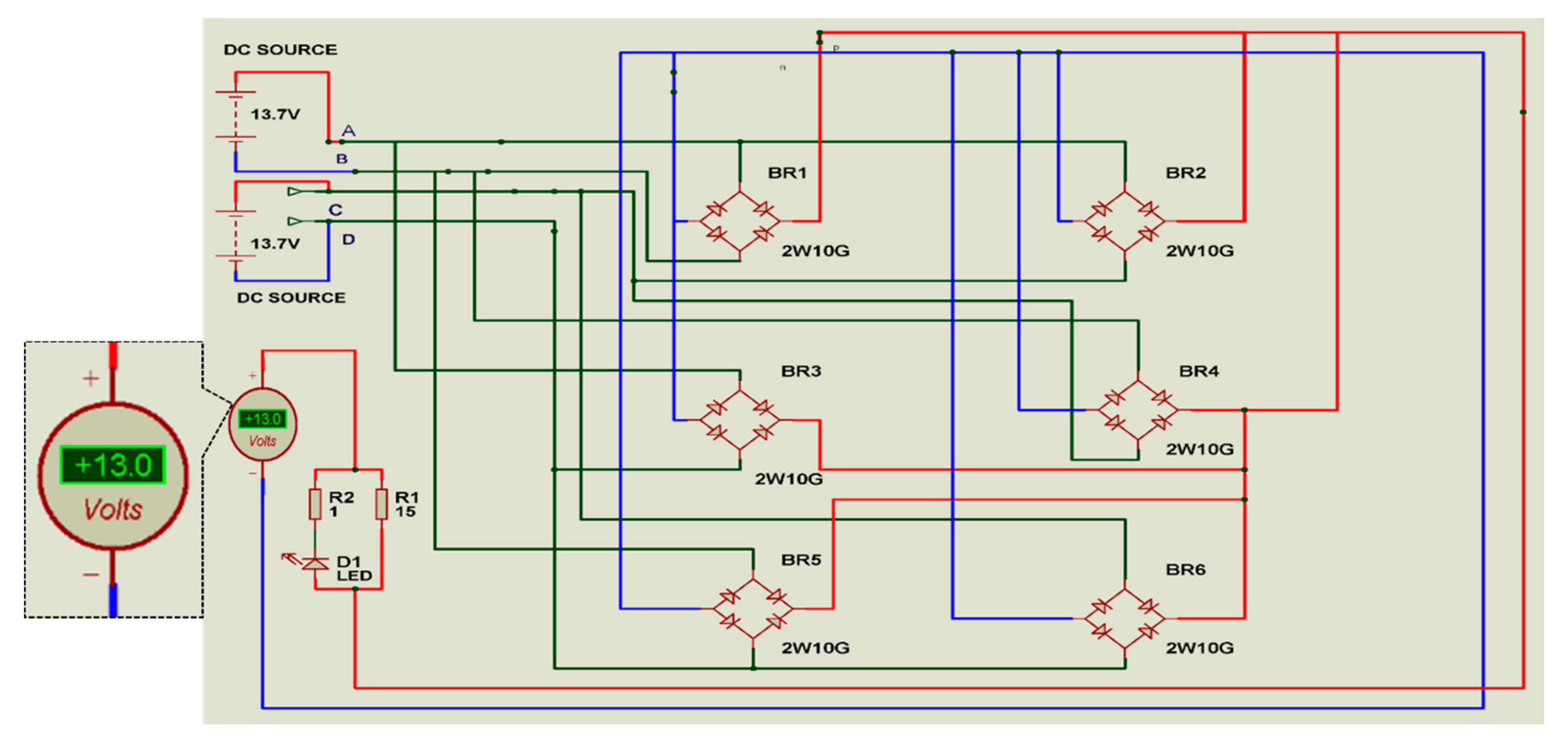
3.1. Onboard Charging Circuit Designed (Polarity Modulator Circuit)

The diode bridge rectifier works like a one-way valve, only letting the positive or negative charge through depending on how they are wired [42]. The two-input terminal of the diode bridge rectifiers is connected to the contact pins; the electric flow happens when these pins touch the charging platform, which is supplied by a DC power source consisting of negative and positive charging signals distributed on the platform plates.
The significant advantage of this design is the ability to resolve the misalignment caused by landing problems. This feature is critical in drone applications at reduced landing precision when depending on the landing and positioning support systems’ performance. The onboard electronic circuit design was configured to minimize the component weights and to decrease design complications and cost. The charging voltage for the UAV battery was regulated on the supply side to match the battery specification and save weight and size for the onboard charging circuit. Figure 3a shows the circuit in non-operational mode. Figure 3b shows the polarity circuit with four contact pins in operation and providing different charging signals. The (+) symbol represents the charging signal when the onboard pin touches a positive charge tile, but the (−) symbol represent the negative charging signal when the onboard pin touches the negative charge tile. In this case, all the bridge rectifiers are operational and modulating the polarities, as needed for the battery. As shown in the circuit diagram, the diodes circuits use a bold color. This diagram shows the power signal flows through the bridge rectifiers until it reaches the main terminals that feed the battery. Therefore, the inactive diodes are shown in a transparent color, which gives the notion of an off activity. Figure 3c shows two contact pins that are active and in contact to the charging pad tiles, thus providing two different charging polarities to the circuit design, while the other pins are considered out of range or not connected to any of those copper tiles; five bridge rectifiers are active and modulating the signal as needed for the battery. Figure 3d shows three active contact pins while the others are out of range, and, as previously seen, the charging circuit modulates the signal while improving its modulation. As discussed in the section above, the 16 copper plates can be represented mathematically with standard logical truth tables with 24 different cases. However, the logical truth table cannot express real case scenarios with the UAV landing for charging at different angles and orientations. Therefore, a simulation of randomly landing in 16 cases is illustrated in Table 1, which shows the probabilities of charging as: “+,” which represents a positive signal, “−,” which represents a negative signal, and “0,” which represents a case when the pin either falls out of range when the UAV lands or falls between the isolation gaps between the copper plates, which is indicated as “null”.

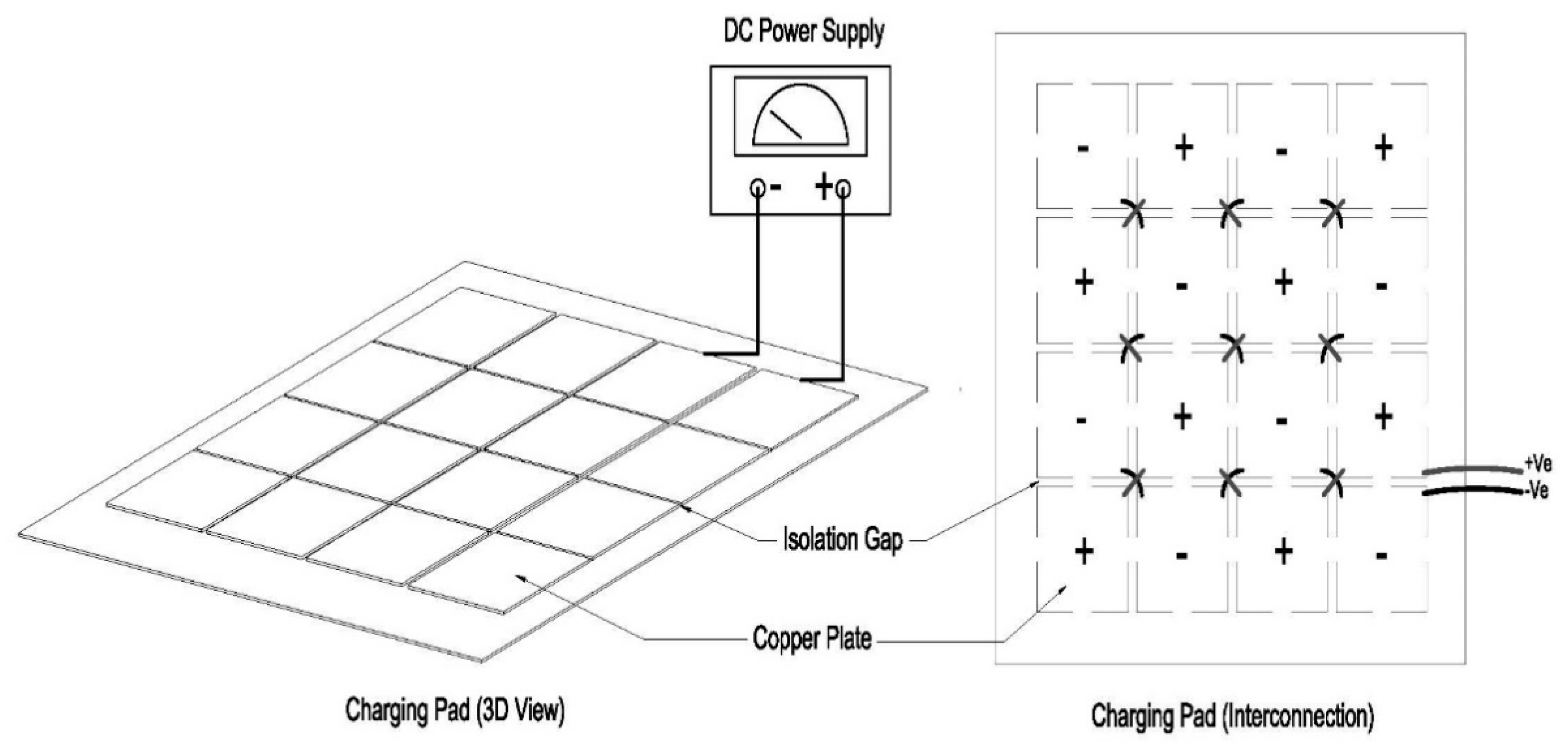
3.2. Landing Platform Design

A proposed design diagram of the system is illustrated in Figure 4. The recharge station and UAV landing pad passively host the UAV. This passive approach to creating landing error tolerance was selected based on existing methods of position error correction due to its simplicity. The ground platform hosts the landing circuit, which is connected to an energy source. The proposed system uses a chessboard design for the platform. This method provides the connectivity of positive and negative polarities for the copper plate, which was selected to overcome the landing’s potential inaccuracy. Two copper plates are connected to the DC power source to provide power for the rest of the platform copper plates. To avoid short-circuiting, the isolation gap between the plates was made to be slightly further away than that of the drone pins’ contact area.
The proposed charging system uses a designed ground platform that aids the charging process by the following procedure below:
  • The positive–negative consecutive square copper plates are sized in such a way that their side lengths are smaller than the shortest distance between every two legs of the drone.
  • The ground station’s dimensions were estimated from a repeatability test of the landing process in the same location to find the maximum area of landing error [43], which was found to be 70 × 70 cm.
  • The space between each consecutive square piece in the chess platform was made to be slightly larger than the drone terminal’s spring pin contact.

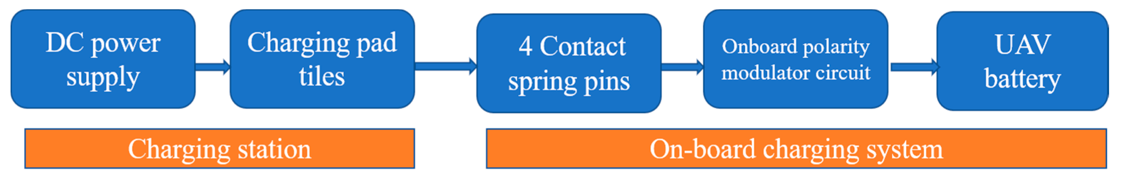
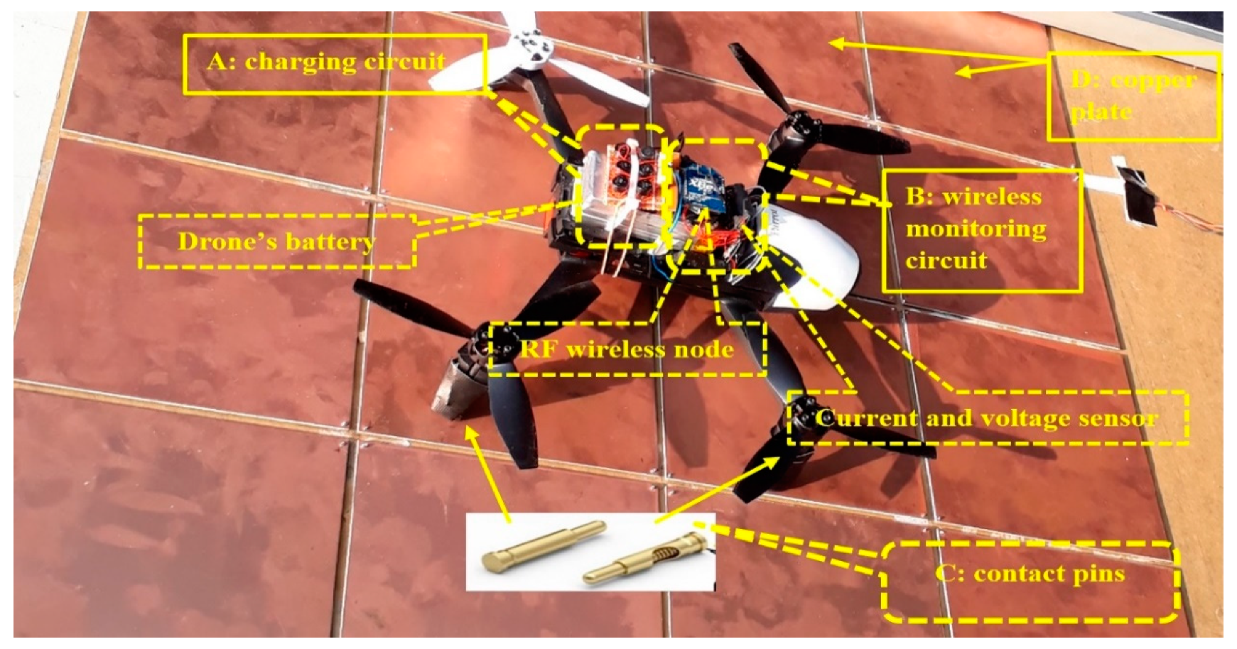
4. Charging System Integration

Spring pins were installed at each end of the UAV skids that were then wired to the modulator circuit. The six-bridge rectifier diodes of the onboard modulator circuit board was configured such that all positive diode terminals were connected to form the main positive terminal. This system provides the positive charge signal for the battery and the same for the diodes’ negative terminals. However, two other input terminals were attached and configured to cover any possibility with the drone’s pins. The integration of the overall proposed system is depicted in Figure 5. This structural design of the diode bridge works to provide the drone battery with a single-pole supply irrespective of the drone y-axis. The charging process can be started with minimum two pins attached to the plates. The maximum is when all four pins are attached to the charging platform, and each pin may have a different polarity to the others depending on the plates’ charging polarity touch. Concerning the forward drop voltage of the diodes, the UAV battery terminals’ power is balanced to the voltage of its full load.

5. Results

5.1. Charging Circuit Simulation Results

The results for the simulation regarding the charging circuit design can be seen in Figure 6. The six bridge rectifiers act simultaneously with the input signal to interpret polarity modulation from the pins to the battery. As shown in the figures mentioned above, the charging signal inputs are represented by black-colored wiring; however, the output of the modulated charge signal is demonstrated in red and blue colors for the positive and negative charging signals, respectively. Finally, the plate needs at least one positive contact and one negative pin contact for charging to commence. Furthermore, the simulation results indicated that all possibilities of UAV landing could give 13.0 V to the battery, which matched the battery charging demand.

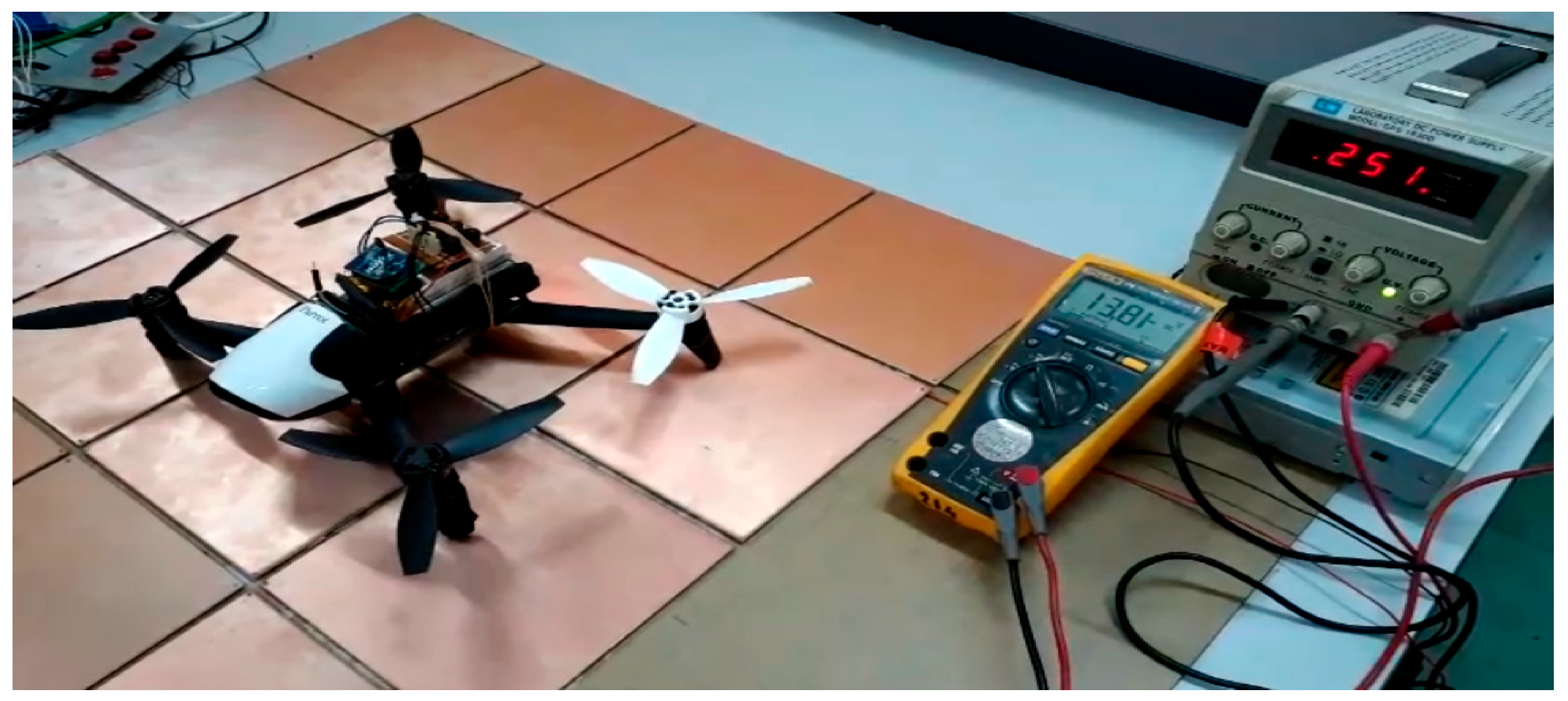
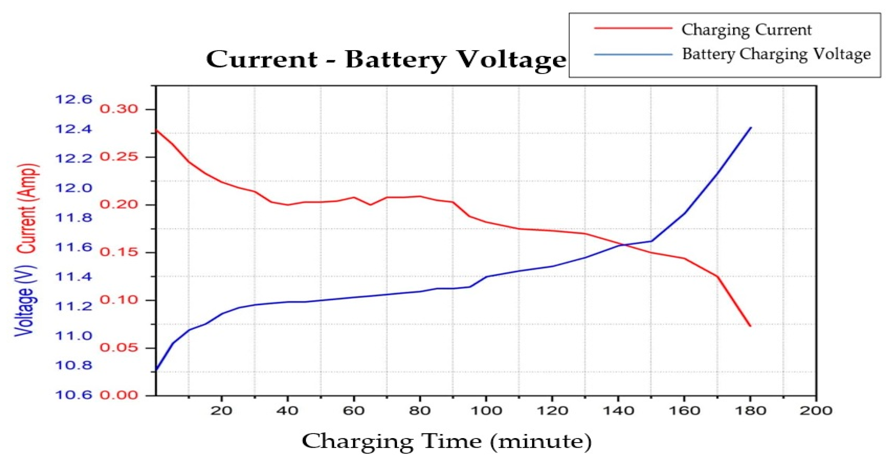
5.2. Charging Performance

A DC power supply was used to simulate the standard commercial power supply. The configurations for the supply power were set based on the charger manufacturer’s specifications.
The drone battery is a rechargeable, 2700 mAh, high-density, lithium-ion polymer. Briefly, the range of charger output current was limited to (1.2 A). The charging current was set to 0.27 A, and charging voltage was set to 13 V. However, the battery capacity for input power was set to 12.4 V. Tests were conducted to assess the direct contact method’s reliability for charging the onboard drone battery. The outcome of these attempts confirmed the presented method, as the current was found to flow from the power supply to the battery through the chessboard and the onboard contacts once the drone touched the charging platform. Figure 7 shows that the initial charge started at 0.279 A and gradually reduced over time due to Ohm’s law. Furthermore, the battery voltage started at the point of the minimum battery cut-off threshold, which was the point that the battery was considered fully discharged. The standard in the experimented battery was 10.4 V, and it rose over time to an open circuit voltage of 12.4 V, which was the maximum potential difference when there was no current that could flow through the battery cells.
The charging process depends on the battery’s state of charge, the type of power source, and the weather conditions. Upon automatic drone landing, the onboard battery can reach full charge in approximately 180 min.
For an analysis of the direct contact and the efficiency of the polarity modulator circuit, the supply voltage was adjusted to 13.7 V and the onboard circuit output voltage (which is the final input voltage for the battery) was adjusted to fit with the 13 V while considering the value of R Load for the copper plate and the polarity modulator circuit, which was 50 Ω. The following calculation is for the difference between the I in (input current supply) and the I out (output current) of the circuit:
I out =   V out R Load
where I out = 0.26 A. therefore, moving forward with the calculation of efficiency, the charging circuit with a starting input current ( I in ) of 0.279 A was calculated to be 88.42%. The efficiency of the charging system was calculated using the ratio of the power out from the circuit to the power generated by the DC power supply as follows:
η = V out   ×   I out V in × I in   %
where ƞ is the charging efficiency in percent, V out   is the output voltage (circuit), I out is the output current (circuit), V in is the input voltage supply, and I in is the input current supply.
Table 2 shows that the proposed method’s efficiency was estimated to reach 88.42% at the start of charging, as illustrated in Figure 6, by using the power efficiency equation shown above. Compared to related work that has mostly used wireless charging methods, this method was found to have a superior charging performance.
It was clear that the maximum efficiency was attained when the onboard battery reached its approximate full charge value; this explained the potential losses of the direct contact recharging process. The losses can be classified as follows:
  • Contact losses due to the quality of the spring contact pins, copper plates, and wires. Their quality can be improved through the use of better materials such as carbon brushes and through the enlargement of the wires’ cross-section area.
  • Voltage regulation losses, which can be reduced by selecting suitable solar panel specifications and applying the voltage matching concept [46,47].
  • Measurement losses, which can be improved with high-efficiency sensors such as Hall-effect current and voltage sensors.

5.3. Landing Probability Simulation Result

Tests were conducted to evaluate the relationship between the size of the copper plates and the distance between the contact pins on the UAV skids. A simulation model for landing operation was established with the Java programming language. In this simulation model, the parameters of the distance between contact pins, the size of the landing pad that hosts the copper plates, and the spaces in between the plates were considered to be fixed. Furthermore, the size and number of plates were kept adjustable to find the optimal charging operation set up. The landing process application was simulated 200 times, and each time, the landing and charging effectiveness was recorded in percent. However, the program recorded the position and the contact pin when it touched the copper plates, or it recorded “0”, which meant “no signal or null” if the pins were out of the plates’ range. To learn more about the choice of the sizing of the charging plates, we simulated five different sizes of 10 × 10 cm, 12 × 12 cm, 14 × 14 cm, 16 × 16 cm, and 18 × 18 cm. Table 3 illustrates the size choice, number of plates, and percentage of charging possibilities. By changing the number of randomly simulated landing repeatability tests, we were able to find the charging probability percentage (the percentage of successful charging cases or the achievements of landing that lead to confirmed charging cases for the UAV quadcopter) and the appropriate distance between contact pins on the UAV skids, which were ultimately fixed to a (X) configuration of 25.4 cm in width and 18.6 cm in length.

6. Conclusions

For this study, a charging platform with a chess-pad configuration was applied to a landing UAV. All onboard components were exceptionally light and compact. By its design, the proposed of a small diode bridge configuration with only six pieces and four spring contact pins was installed in a UAV to directly touch its landing station. Using direct link configuration, it showed 86% efficiency of the battery recharging system compared to wireless charging methods. A simulation for the dimensions of the platform regarding the design of the plates could be configured to the required shape and size of any UAV. The onboard part of the charging system and the configuration of the six diode bridge rectifiers enabled the battery to charge even if just two contact pins successfully touched the platform.
Future work should be done to address the following problems. The landing pad design configuration could mitigate moisture issues to resistively sense changes in load between adjacent plates. Additionally, the current flow could be restricted in the ground platform to help avoid short circuiting, and a heating component could be included after precipitation to evaporate moisture. It is also conceivable for indoor and outdoor ground stations to use independent power sources. The development of this platform offers a practical and scalable UAV charging system.

Author Contributions

Conception and design of study, M.R.A.-O., W.Z.W.H., M.A.M. and N.A.; Analysis and/or interpretation of data, M.R.A.-O., W.Z.W.H.; Drafting the manuscript and revising the manuscript critically for important intellectual content, M.R.A.-O. and W.Z.W.H.; Approval of the version of the manuscript to be published, M.R.A.-O., W.Z.W.H., M.A.M. and N.A. All authors have read and agreed to the published version of the manuscript.

Funding

This research received no external funding.

Acknowledgments

The authors would like to thank the University Putra Malaysia and Ministry of Education for supporting and funding this study under Putra Grant scheme of Universiti Putra Malaysia and Ministry of Higher Education Malaysia with the grant number is GP-IPB/2020/967801.

Conflicts of Interest

The authors declare no conflict of interest.

References

  1. Mahony, R.; Kumar, V. Aerial Robotics and the Quadrotor. IEEE Robot. Autom. Mag. 2012, 19, 19. [Google Scholar] [CrossRef]
  2. Saarinen, J.; Suomela, J.; Halme, A.; Pavlícek, J. Multientity Rescue System. IFAC Proc. Vol. 2004, 37, 35–40. [Google Scholar] [CrossRef]
  3. Sarunic, P.; Evans, R. Hierarchical model predictive control of UAVs performing multitarget-multisensor tracking. IEEE Trans. Aerosp. Electron. Syst. 2014, 50, 2253–2268. [Google Scholar] [CrossRef]
  4. Lee, B.; Kwon, S.; Park, P.; Kim, K. Active power management system for an unmanned aerial vehicle powered by solar cells, a fuel cell, and batteries. IEEE Trans. Aerosp. Electron. Syst. 2014, 50, 3167–3177. [Google Scholar] [CrossRef]
  5. dji. Available online: https://www.dji.com/ronin-s?site=brandsite&from=homepage (accessed on 30 July 2018).
  6. Lee, D.; Zhou, J.; Lin, W.T. Autonomous battery swapping system for quadcopter. In Proceedings of the 2015 International Conference on Unmanned Aircraft Systems (ICUAS), Denver, CO, USA, 9–12 June 2015; pp. 118–124. [Google Scholar] [CrossRef]
  7. Swieringa, K.A.; Hanson, C.B.; Richardson, J.R.; White, J.D.; Hasan, Z.; Qian, E.; Girard, A. Autonomous battery swapping system for small-scale helicopters. In Proceedings of the 2010 IEEE International Conference on Robotics and Automation, Anchorage, Alaska, 4–8 May 2010; pp. 3335–3340. [Google Scholar]
  8. Suzuki, K.A.; Kemper Filho, P.; Morrison, J.R. Automatic battery replacement system for UAVs: Analysis and design. J. Intell. Robot. Syst. Theory Appl. 2012, 65, 563–586. [Google Scholar] [CrossRef]
  9. Kemper, F.P.; Suzuki, K.A.O.; Morrison, J.R. UAV Consumable Replenishment: Design Concepts for Automated Service Stations. J. Intell. Robot. Syst. 2010, 61, 369–397. [Google Scholar] [CrossRef]
  10. Nugent, T.J.; Kare, J.T. Laser power for UAVs. Laser Motiv. White Paper-Power Beaming UAVs NWEN 2010, 1–9. [Google Scholar]
  11. Ouyang, J.; Che, Y.; Xu, J.; Wu, K. Throughput Maximization for Laser-Powered UAV Wireless Communication Systems. In Proceedings of the 2018 IEEE International Conference on Communications Workshops (ICC Workshops), Kansas City, MO, USA, 20–24 May 2018; pp. 1–6. [Google Scholar]
  12. Laser Beaming Recharges UAV in Flight. 2018. Available online: https://www.popularmechanics.com/flight/drones/a7966/how-it-works-laser-beaming-recharges-uav-in-flight-11091133/ (accessed on 28 July 2012).
  13. Brown, W.C. Experiments Involving a Microwave Beam to Power and Position a Helicopter. IEEE Trans. Aerosp. Electron. Syst. 1969, 5, 692–702. [Google Scholar] [CrossRef]
  14. Nugent, J.T.J.; Kare, J.T. Laser power beaming for defense and security applications. In Proceedings of the SPIE 8045, Unmanned Systems Technology XIII, 804514, Orlando, FL, USA, 23 May 2011. [Google Scholar] [CrossRef]
  15. Ireland, M.L.; Anderson, D. Optimisation of Trajectories for Wireless Power Transmission to a Quadrotor Aerial Robot. J. Intell. Robot. Syst. 2018, 95, 567–584. [Google Scholar] [CrossRef] [Green Version]
  16. Kurs, A.; Karalis, A.; Moffatt, R.; Joannopoulos, J.D.; Fisher, P.; Soljačić, M. Wireless Power Transfer via Strongly Coupled Magnetic Reconances. Science 2007, 317, 83–86. [Google Scholar] [CrossRef] [Green Version]
  17. Karalis, A.; Joannopoulos, J.D.; Soljacicb, M. Efficient wireless non-radiative mid-range energy transfer. Ann. Phys. 2008, 323, 34–48. [Google Scholar] [CrossRef] [Green Version]
  18. Fu, M.; Zhang, T.; Ma, C.; Zhu, X. Efficiency and Optimal Loads Analysis for Multiple-Receiver Wireless Power Transfer Systems. IEEE Trans. Microw. Theory Tech. 2015, 63, 801–812. [Google Scholar] [CrossRef]
  19. Zhang, W.; Mi, C.C. Compensation Topologies of High-Power Wireless Power Transfer Systems. IEEE Trans. Veh. Technol. 2016, 65, 4768–4778. [Google Scholar] [CrossRef]
  20. Bi, Z.; Kan, T.; Mi, C.C.; Zhang, Y.; Zhao, Z.; Keoleian, G.A. A review of wireless power transfer for electric vehicles: Prospects to enhance sustainable mobility. Appl. Energy 2016, 179, 413–425. [Google Scholar] [CrossRef] [Green Version]
  21. Henze, C.P.; Nicholls, K.E. Method and apparatus for charging a plurality of electric vehicles. U.S. Patent No. 5,803,215, 8 September 1998. [Google Scholar]
  22. Song, C.; Kim, H.; Kim, Y.; Kim, D.; Jeong, S.; Cho, Y.; Lee, S.; Ahn, S.; Kim, J. EMI Reduction Methods in Wireless Power Transfer System for Drone Electrical Charger Using Tightly Coupled Three-Phase Resonant Magnetic Field. IEEE Trans. Ind. Electron. 2018, 65, 6839–6849. [Google Scholar] [CrossRef]
  23. Joseph, B.A.; Graves, J.L.; Olson, T.B. System and method for managing electromagnetic interference for electronic devices. U.S. Patent No. 10,459,874, 29 October 2019. [Google Scholar]
  24. Covic, G.A.; Boys, J.T. Inductive Power Transfer. Proc. IEEE 2013, 101, 1276–1289. [Google Scholar] [CrossRef]
  25. Shinohara, N. Power without wires. IEEE Microw. Mag. 2011, 12, S64–S73. [Google Scholar] [CrossRef]
  26. Campi, T.; Cruciani, S.; Feliziani, M. Wireless Power Transfer Technology Applied to an Autonomous Electric UAV with a Small Secondary Coil. Energies 2018, 11, 352. [Google Scholar] [CrossRef] [Green Version]
  27. Campi, T.; Cruciani, S.; Maradei, F.; Feliziani, M. Near-Field Reduction in a Wireless Power Transfer System Using LCC Compensation. IEEE Trans. Electromagn. Compat. 2017, 59, 686–694. [Google Scholar] [CrossRef]
  28. Campi, T.; Cruciani, S.; De Santis, V.; Feliziani, M. EMF Safety and Thermal Aspects in a Pacemaker Equipped With a Wireless Power Transfer System Working at Low Frequency. IEEE Trans. Microw. Theory Tech. 2016, 64, 1–8. [Google Scholar] [CrossRef]
  29. Jawad, A.M.; Nordin, R.; Gharghan, S.K.; Jawad, H.M.; Ismail, M. Opportunities and Challenges for Near-Field Wireless Power Transfer: A Review. Energies 2017, 10, 1022. [Google Scholar] [CrossRef]
  30. Nair, V.V.; Choi, J.R. An Efficiency Enhancement Technique for a Wireless Power Transmission System Based on a Multiple Coil Switching Technique. Energies 2016, 9, 156. [Google Scholar] [CrossRef] [Green Version]
  31. Feliziani, M.; Campi, T.; Cruciani, S.; Maradei, F.; Grasselli, U.; Macellari, M.; Schirone, L.; Robust, M.F. LCC compensation in wireless power transfer with variable coupling factor due to coil misalignment. In Proceedings of the 2015 IEEE 15th International Conference on Environment and Electrical Engineering (EEEIC), Rome, Italy, 10–13 June 2015; pp. 1181–1186. [Google Scholar]
  32. Campi, T.; Dionisi, F.; Cruciani, S.; De Santis, V.; Feliziani, M.; Maradei, F. Magnetic field levels in drones equipped with Wireless Power Transfer technology. In Proceedings of the 2016 Asia-Pacific International Symposium on Electromagnetic Compatibility (APEMC), Shenzhen, China, 18–21 May 2016; Volume 1, pp. 544–547. [Google Scholar] [CrossRef]
  33. Choi, C.H.; Jang, H.J.; Lim, S.G.; Lim, H.C.; Cho, S.H.; Gaponov, I. Automatic wireless drone charging station creating essential environment for continuous drone operation. In Proceedings of the 2016 International Conference on Control, Automation and Information Sciences (ICCAIS), Ansan, Korea, 27–29 October 2016; pp. 132–136. [Google Scholar] [CrossRef]
  34. Bin Junaid, A.; Lee, Y.; Kim, Y. Design and implementation of autonomous wireless charging station for rotary-wing UAVs. Aerosp. Sci. Technol. 2016, 54, 253–266. [Google Scholar] [CrossRef]
  35. Bin Junaid, A.; Konoiko, A.; Zweiri, Y.; Sahinkaya, M.N.; Seneviratne, L.D. Autonomous Wireless Self-Charging for Multi-Rotor Unmanned Aerial Vehicles. Energies 2017, 10, 803. [Google Scholar] [CrossRef]
  36. Almassri, A.M.M.; Hasan, W.Z.W.; Ahmad, S.A.; Ishak, A.J. A sensitivity study of piezoresistive pressure sensor for robotic hand. In RSM 2013 IEEE Regional Symposium on Micro and Nanoelectronics; Institute of Electrical and Electronics Engineers (IEEE): New York, NY, USA, 2013; pp. 394–397. [Google Scholar]
  37. Schmidt, H. Method and apparatus for charging and/or charge exchange between a plurality of series connected energy storage devices. U.S. Patent 5,767,660, 16 June 1998. [Google Scholar]
  38. Magaña, E.J.C.; Esteban-Campillo, D.; Jiménez, D.S.; Maza, I.; Caballero, F. Device and method for use with unmanned aerial vehicles. U.S. Patent No. 9,481,458, 1 November 2016. [Google Scholar]
  39. Sidek, M.; Hasan, W.; Kadir, M.; Shafie, S.; Radzi, M.; Ahmad, S.; Marhaban, M. GPS based portable dual-axis solar tracking system using astronomical equation. In 2014 IEEE International Conference on Power and Energy (PECon); Institute of Electrical and Electronics Engineers (IEEE): New York, NY, USA, 2014; pp. 245–249. [Google Scholar]
  40. Leonard, J.; Savvaris, A.; Tsourdos, A. Energy Management in Swarm of Unmanned Aerial Vehicles. J. Intell. Robot. Syst. 2014, 74, 233–250. [Google Scholar] [CrossRef]
  41. Cisek, K.; Zolich, A.; Klausen, K.; Johansen, T.A. Ultra-wide band Real time Location Systems: Practical implementation and UAV performance evaluation. In Proceedings of the 2017 Workshop on Research, Education and Development of Unmanned Aerial Systems (RED-UAS), Linköping, Sweden, 3–5 October 2017; pp. 204–209. [Google Scholar] [CrossRef] [Green Version]
  42. Shafie, S.; Kawahito, S.; Halin, I.A.; Hasan, W.Z.W. Non-Linearity in Wide Dynamic Range CMOS Image Sensors Utilizing a Partial Charge Transfer Technique. Sensors 2009, 9, 9452–9467. [Google Scholar] [CrossRef]
  43. Al-Obaidi, M.; Mustafa, M.A.; Hasan, W.Z.W.; Azis, N.; Sabry, A.H.; Ang, S.; Hamid, Z.H.A. Efficient Charging Pad for Unmanned Aerial Vehicle Based on Direct Contact. In Proceedings of the 2018 IEEE 5th International Conference on Smart Instrumentation, Measurement and Application (ICSIMA), Songkla, Thailand, 28–30 November 2018; pp. 1–5. [Google Scholar] [CrossRef]
  44. Jonah, O.; Georgakopoulos, S.V. Wireless Power Transfer in Concrete via Strongly Coupled Magnetic Resonance. IEEE Trans. Antennas Propag. 2012, 61, 1378–1384. [Google Scholar] [CrossRef]
  45. Jung, S.; Lee, T.; Mina, T.; Ariyur, K.B. Inductive or Magnetic Recharging for Small UAVs. SAE Tec. Paper Ser. 2012. [Google Scholar] [CrossRef]
  46. Sabry, A.H.; Hasan, W.Z.W.; Kadir, M.A.; Radzi, M.A.M.; Shafie, S. DC-based smart PV-powered home energy management system based on voltage matching and RF module. PLoS ONE 2017, 12, e0185012. [Google Scholar] [CrossRef] [Green Version]
  47. Sabry, A.H.; Hasan, W.Z.W.; Zainal, M.; Amran, M.; Shafie, S. Alternative Solar-Battery Charge Controller to Improve System Efficiency. Appl. Mech. Mater. 2015, 785, 156–161. [Google Scholar] [CrossRef]
Figure 1. Main system components of the presented charging platform. UAV: unmanned aerial vehicle.
Applsci 10 08365 g001
Figure 2. Lab test for the configuration of the chess pad charging platform.
Applsci 10 08365 g002
Figure 3. The proposed on-board circuit with a contacted sample of the circuit with all connections which diode bridge rectifiers (BR1, BR2, BR3, BR4, BR5, BR6) connected to four contact pin (A, B, C, D) and have four example of operation cases represented in (a), two positive and two negatives in (b), one positive, one negative, and two disconnected in (c), one positive, two negatives, and one disconnected in (d).
Applsci 10 08365 g003
Figure 4. Proposed charging system platform.
Applsci 10 08365 g004
Figure 5. Experimental setup of the onboard system.
Applsci 10 08365 g005
Figure 6. Simulation results regarding four contact pins: 2 positives (A, C) and two negatives (B, D).
Applsci 10 08365 g006
Figure 7. The current supply and battery voltage during charging.
Applsci 10 08365 g007
Table 1. The cases of charging conditions, where the four contact points and the two signals (positive and negative) are embedded in the truth table to review charging condition probabilities.
Drone IDPin APin BPin CPin DCharging Status
0++Charging
1Not Charging
2+Charging
3+Charging
40+Charging
5++Charging
6++Charging
7++++Not Charging
8++Charging
9++Charging
10++Charging
11++0Charging
12+Charging
130++Charging
14++Charging
15++Charging
Table 2. Comparison table for charging efficiency.
Charging Efficiency, ƞ (%)MethodReference
88.42Contact ChargingThis Work
40–50Wireless Power Transfer[44]
52Wireless Power Transfer[17]
76Wireless Power Transfer[26]
65Wireless Power Transfer[33]
>50Wireless Power Transfer[34]
75Wireless Power Transfer[35]
13.33Inductive Charging[45]
Table 3. Charging probability with different plate sizes.
Details of DesignNumber of PlatesCharging Probability Percentage (%)
10 × 10 cm3657
12 × 12 cm2555
14 × 14 cm1669
16 × 16 cm1676
18 × 18 cm971
Publisher’s Note: MDPI stays neutral with regard to jurisdictional claims in published maps and institutional affiliations.

