Dynamic Analysis of Planetary Gear with Root Crack in Sun Gear Based on Improved Time-Varying Mesh Stiffness


Abstract
:Featured Application
Abstract
1. Introduction
2. Stiffness Calculation
2.1. Mesh Stiffness Calculation of Healthy Gears
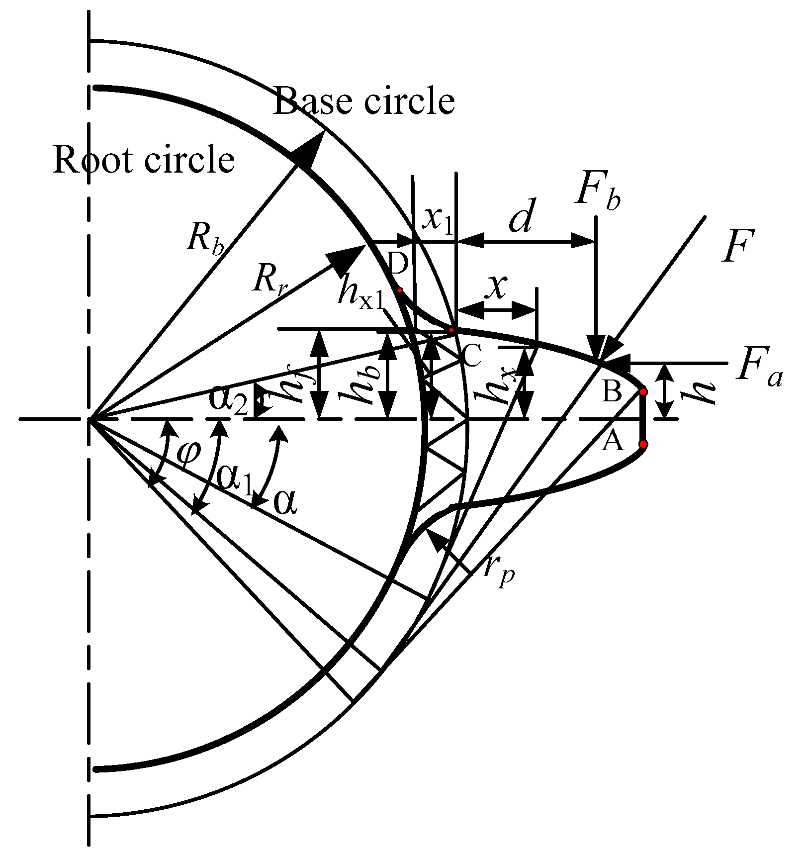
2.1.1. The Diameter of the Root Circle Is Smaller than the Base Circle
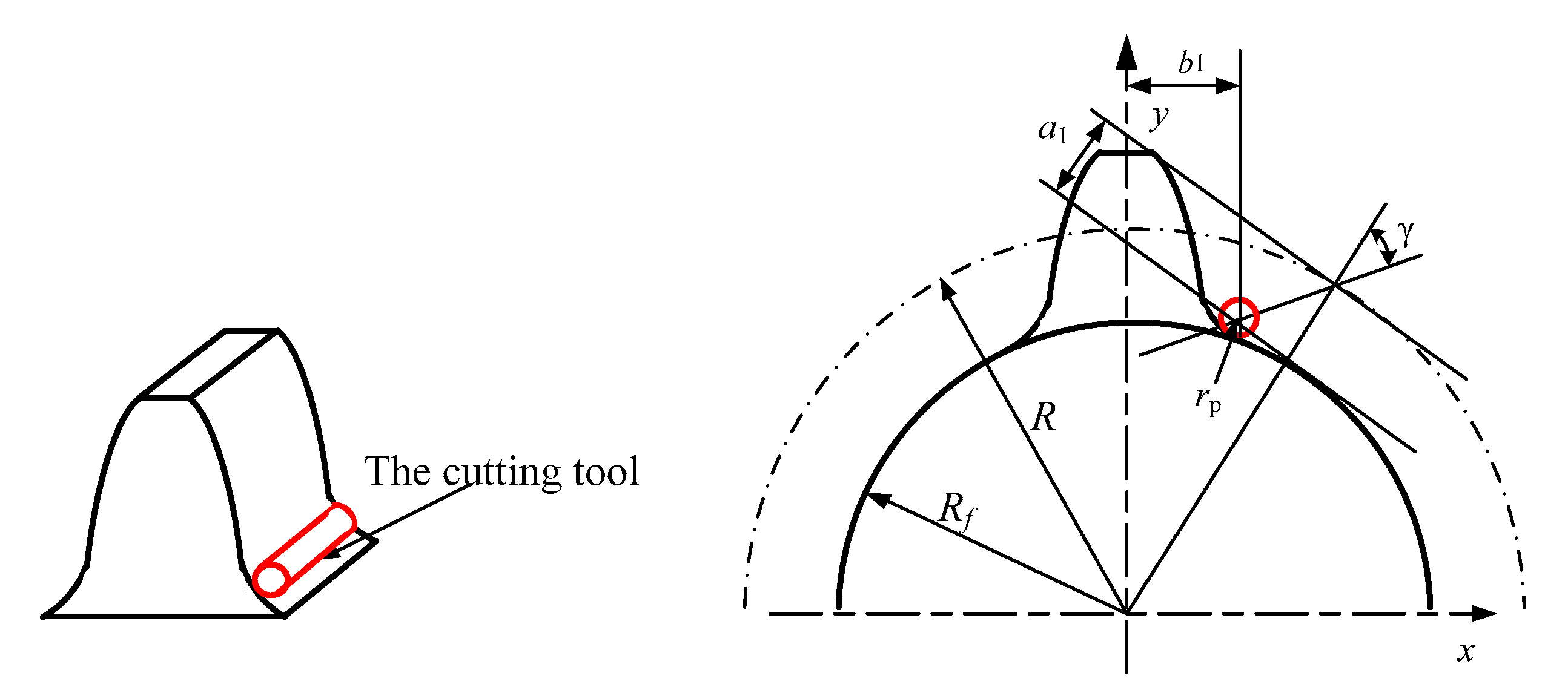
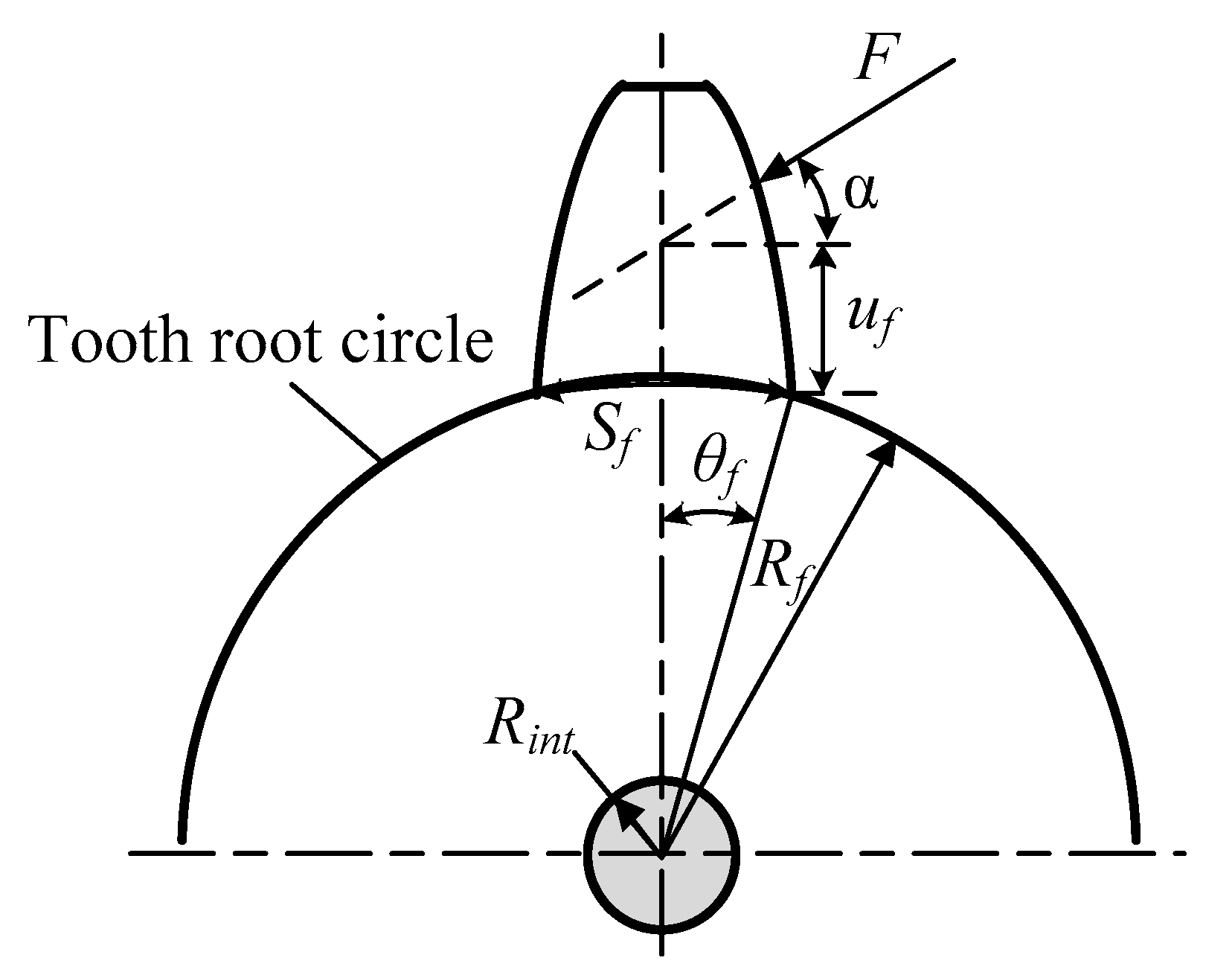
2.1.2. The Diameter of the Root Circle Is Larger than the Base Circle
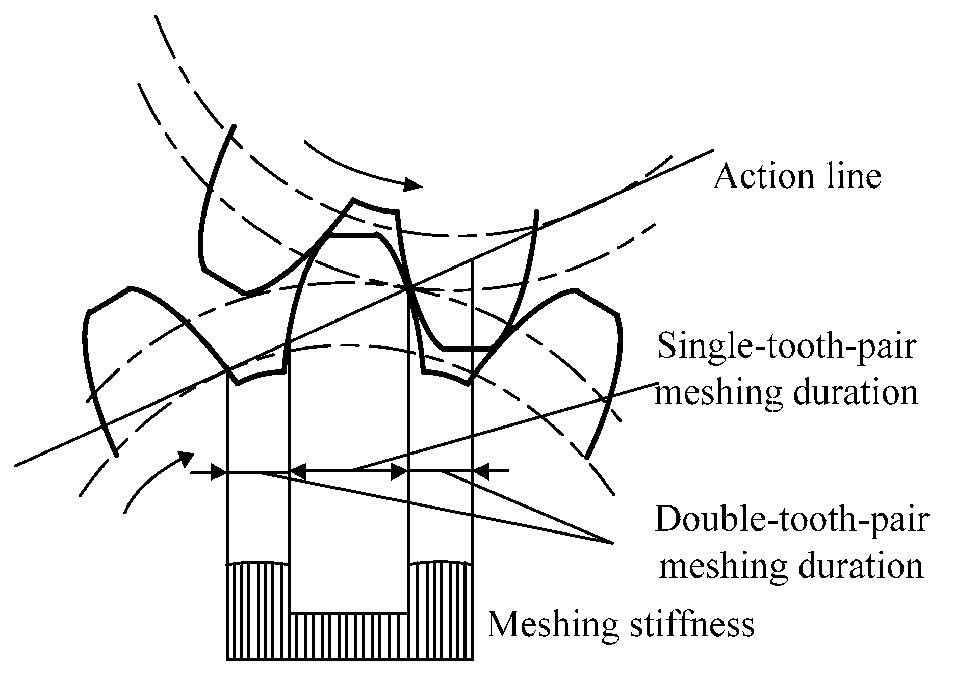
2.1.3. Calculation of Comprehensive Mesh Stiffness
2.2. Mesh Stiffness Calculation of Crack Gear
2.2.1. The Diameter of the Root Circle Is Smaller than the Base Circle
2.2.2. The Diameter of the Root Circle Is Larger than That of the Base Circle
3. Dynamic Equation Modeling of the Planetary Gear Train
4. Simulation and Experimental Analysis
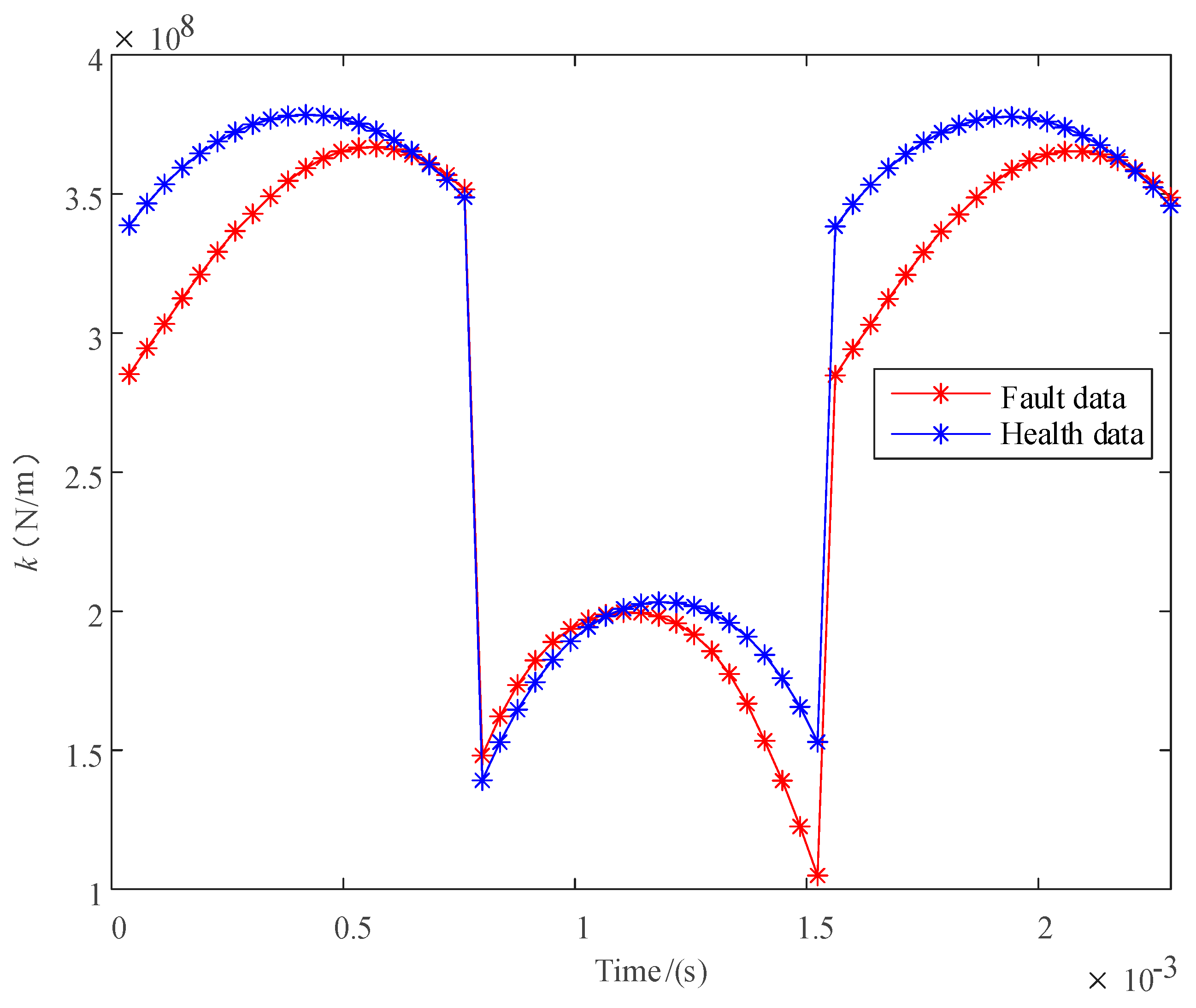
4.1. Mesh Stiffness Analysis
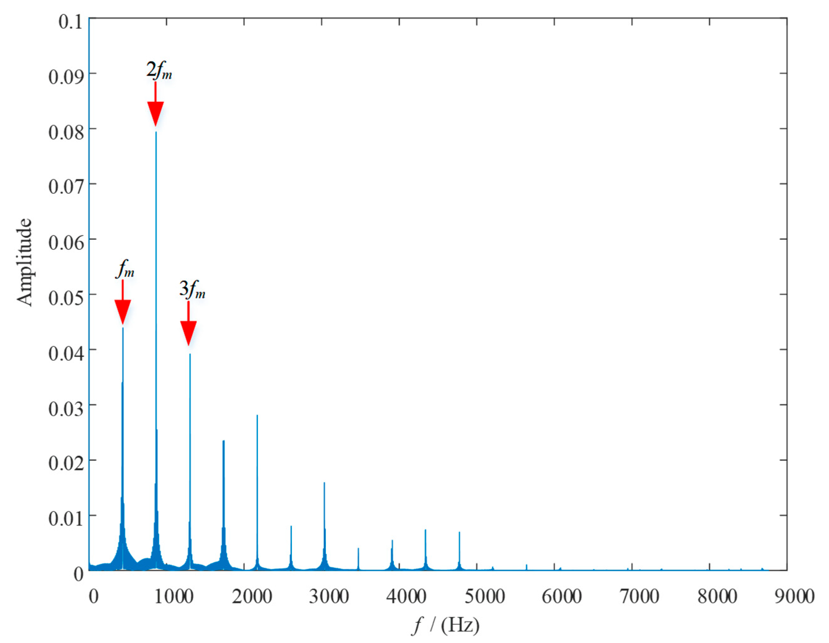
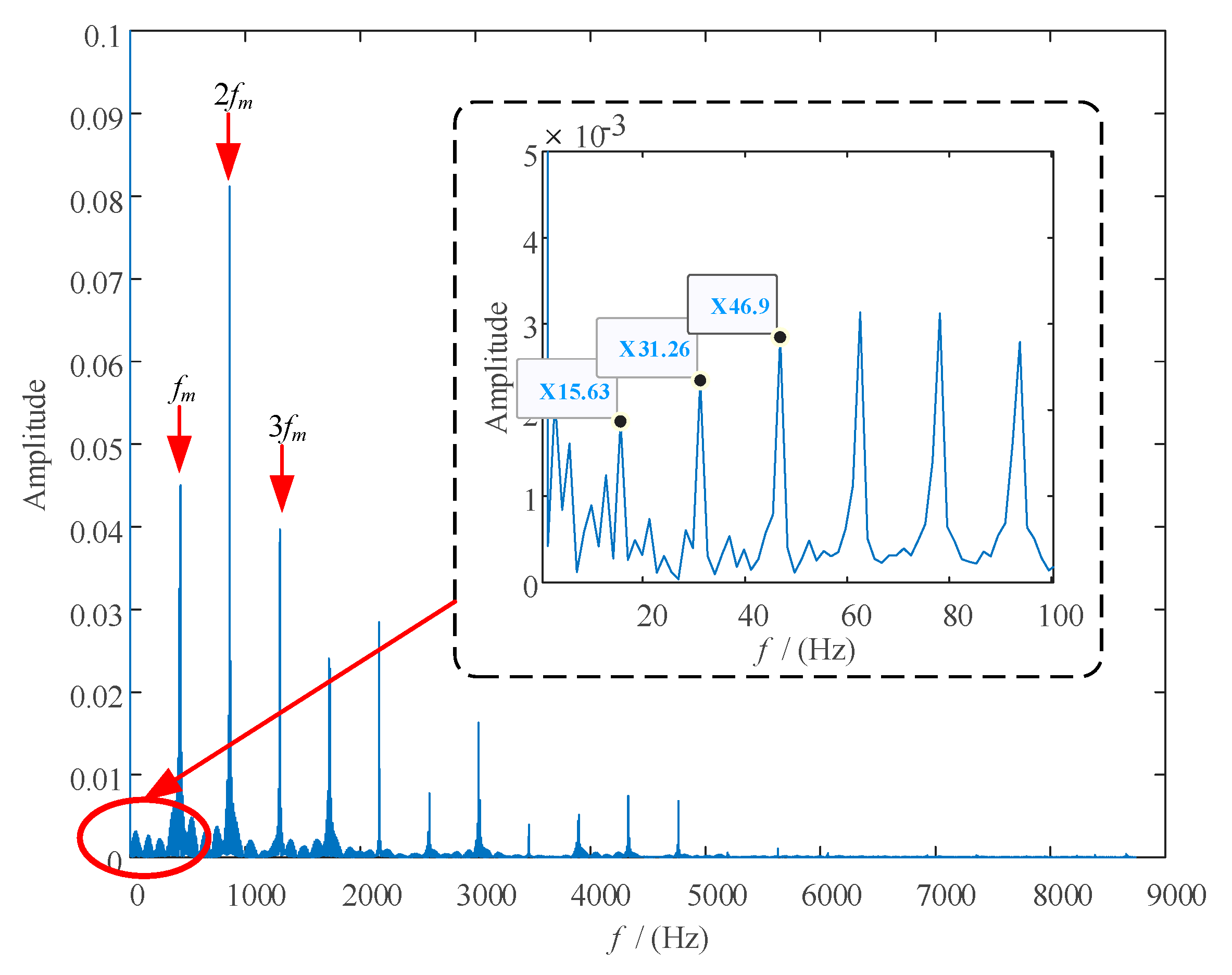
4.2. Simulation Analysis
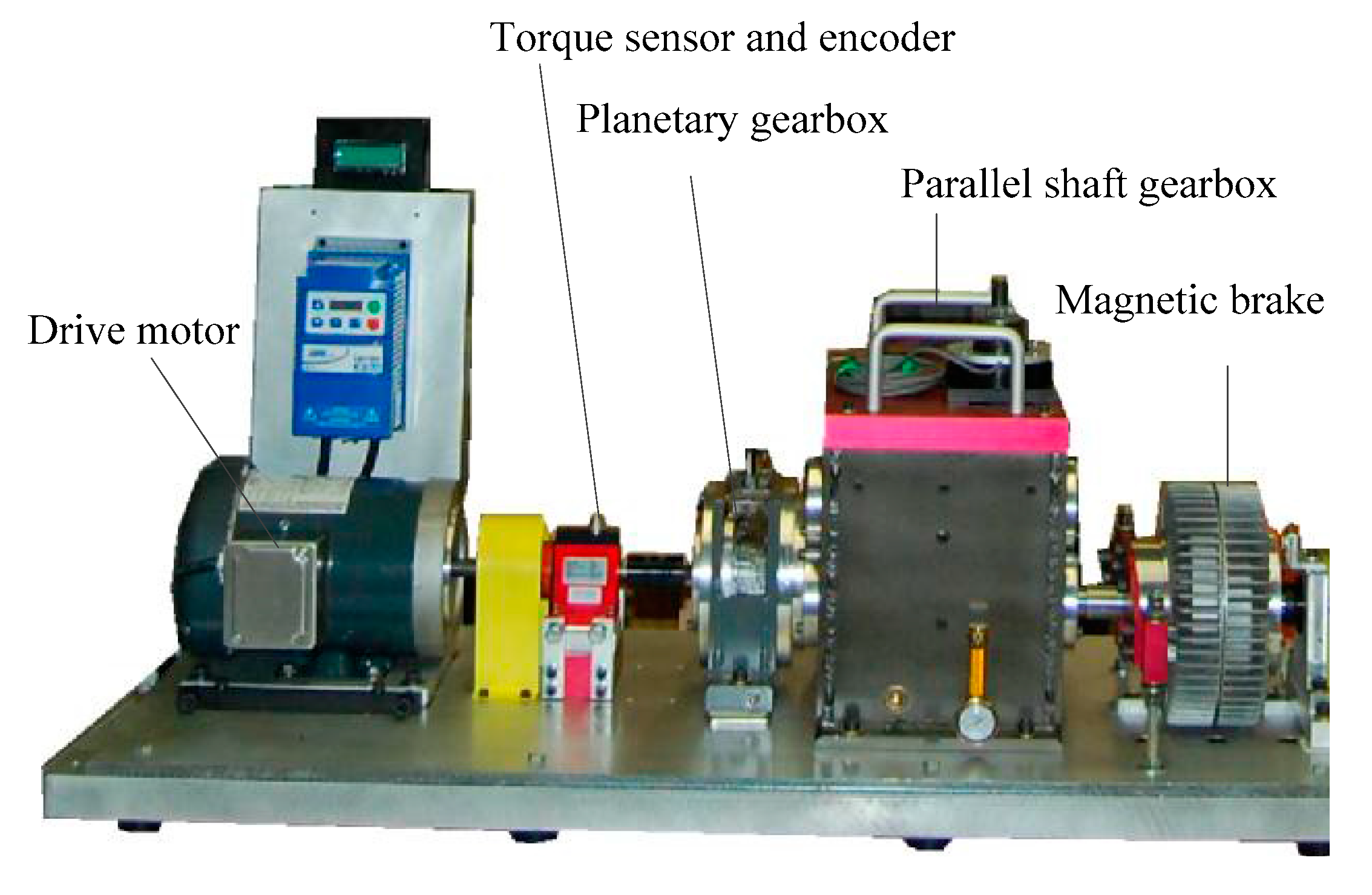
4.3. Experimental Analysis
5. Discussion
Author Contributions
Funding
Conflicts of Interest
References
- Weber, C.; Banaschek, K. The Deformation of Loaded Gears and the Effect on Their Load Carrying Capacity; Part I: Elastic Deformation of the Teeth and the Adjoining Parts of the Body of the Wheel; Report No. 3, (N.Report No. 102); British Department of Scientific and Industrial Research, Sponsored Research (Germany): London, UK, 1949. [Google Scholar]
- Cornell, R.W. Compliance and stress sensitivity of spur gear teeth. J. Mech. Transm. Autom. 1981, 103, 447–459. [Google Scholar] [CrossRef] [Green Version]
- Yang, D.C.H.; Lin, J.Y. Hertzian damping, tooth friction and bending elasticity in gear impact dynamics. J. Mech. Transm. Autom. 1987, 109, 189–196. [Google Scholar] [CrossRef]
- Tian, X.H. Dynamic Simulation for System Response of Gearbox Including Localized Gear Faults. Master’s Thesis, University of Alberta, Edmonton, AB, Canada, 2004. [Google Scholar]
- Zhou, X.; Shao, Y.; Lei, Y.; Zuo, M. Time-varying meshing stiffness calculation and vibration analysis for a 16 DOF dynamic model with linear crack growth in a pinion. J. Vib. Acoust. 2012, 134, 011011. [Google Scholar] [CrossRef]
- Liang, X.; Zuo, M.J.; Patel, T.H. Evaluating the time-varying mesh stiffness of a planetary gear set using the potential energy method. Proc. Inst. Mech. Eng. Part C J. Mech. Eng. Sci. 2013, 228, 535–547. [Google Scholar] [CrossRef]
- Liang, X.; Zuo, M.J.; Pandey, M. Analytically evaluating the influence of crack on the mesh stiffness of a planetary gear set. Mech. Mach. Theory 2014, 76, 20–38. [Google Scholar] [CrossRef]
- Wan, Z.; Chen, X.-F.; Zi, Y.; He, W.; He, Z. An improved time-varying mesh stiffness algorithm and dynamic modeling of gear-rotor system with tooth root crack. Eng. Fail. Anal. 2014, 42, 157–177. [Google Scholar] [CrossRef]
- Ma, H.; Pang, X.; Feng, R.; Wen, B. Evaluation of optimum profile modification curves of profile shifted spur gears based on vibration responses. Mech. Syst. Signal Process. 2016, 70, 1131–1149. [Google Scholar] [CrossRef]
- Chen, Z.; Wang, K.; Zhai, W.; Shao, Y. Mesh stiffness evaluation of an internal spur gear pair with tooth profile shift. Sci. China Ser. E Technol. Sci. 2016, 59, 1328–1339. [Google Scholar] [CrossRef]
- Chaari, F.; Fakhfakh, T.; Haddar, M. Analytical modelling of spur gear tooth crack and influence on gear mesh stiffness. Eur. J. Mech. A Solids 2009, 28, 461–468. [Google Scholar] [CrossRef]
- Ma, H.; Song, R.; Pang, X.; Wen, B. Fault feature analysis of a cracked gear coupled rotor system. Math. Probl. Eng. 2014, 2014, 832192. [Google Scholar] [CrossRef] [Green Version]
- Ma, H.; Song, R.; Pang, X.; Wen, B. Time-varying mesh stiffness calculation of cracked spur gears. Eng. Fail. Anal. 2014, 44, 179–194. [Google Scholar] [CrossRef]
- Chen, Z.; Shao, Y. Mesh stiffness calculation of a spur gear pair with tooth profile modification and tooth root crack. Mech. Mach. Theory 2013, 62, 63–74. [Google Scholar] [CrossRef]
- Ma, H.; Pang, X.; Feng, R.; Zeng, J.; Wen, B. Improved time-varying mesh stiffness model of cracked spur gears. Eng. Fail. Anal. 2015, 55, 271–287. [Google Scholar] [CrossRef]
- Chen, Z.; Zhai, W.; Shao, Y.; Wang, K.; Sun, G. Analytical model for mesh stiffness calculation of spur gear pair with non-uniformly distributed tooth root crack. Eng. Fail. Anal. 2016, 66, 502–514. [Google Scholar] [CrossRef]
- Chen, Z.; Zhang, J.; Zhai, W.; Wang, Y.; Liu, J. Improved analytical methods for calculation of gear tooth fillet-foundation stiffness with tooth root crack. Eng. Fail. Anal. 2017, 82, 72–81. [Google Scholar] [CrossRef]
- Chen, Z.; Zhu, Z.; Shao, Y. Fault feature analysis of planetary gear system with tooth root crack and flexible ring gear rim. Eng. Fail. Anal. 2015, 49, 92–103. [Google Scholar] [CrossRef]
- Liang, X.; Zuo, M.J.; Hoseini, M.R. Vibration signal modeling of a planetary gear set for tooth crack detection. Eng. Fail. Anal. 2015, 48, 185–200. [Google Scholar] [CrossRef]
- Liu, L.; Liang, X.; Zuo, M.J. Vibration signal modeling of a planetary gear set with transmission path effect analysis. Measurement 2016, 85, 20–31. [Google Scholar] [CrossRef]
- Li, G.; Li, F.-Y.; Liu, H.; Dong, D. Fault features analysis of a compound planetary gear set with damaged planet gears. Proc. Inst. Mech. Eng. Part C J. Mech. Eng. Sci. 2017, 232, 1586–1604. [Google Scholar] [CrossRef]
- Li, G.; Li, F.; Wang, Y.; Dong, D. Fault Diagnosis for a Multistage Planetary Gear Set Using Model-Based Simulation and Experimental Investigation. Shock. Vib. 2015, 2016, 9263298. [Google Scholar] [CrossRef] [Green Version]
- Meng, Z. Vibration response and fault characteristics analysis of gear based on time-varying mesh stiffness. Mech. Mach. Theory 2020, 148, 103786. [Google Scholar] [CrossRef]
- Ma, H.; Pang, X.; Feng, R.; Song, R.; Wen, B. Fault features analysis of cracked gear considering the effects of the extended tooth contact. Eng. Fail. Anal. 2015, 48, 105–120. [Google Scholar] [CrossRef]
- Yang, Y.; Xia, W.; Han, J.; Song, Y.; Wang, J.; Dai, Y. Vibration analysis for tooth crack detection in a spur gear system with clearance nonlinearity. Int. J. Mech. Sci. 2019, 157, 648–661. [Google Scholar] [CrossRef]
- Yuksel, C.; Kahraman, A. Dynamic tooth loads of planetary gear sets having tooth profile wear. Mech. Mach. Theory 2004, 39, 695–715. [Google Scholar] [CrossRef]


| Parameters | Sun Gear | Planet Gear | Ring Gear | Planet Carrier |
|---|---|---|---|---|
| Number of teeth | 28 | 36 | 100 | - |
| Modulus (mm) | 1 | 1 | 1 | - |
| Young’s modulus (Pa) | 2.068 × 10¹¹ | 2.068 × 10¹¹ | 2.068 × 10¹¹ | - |
| Poisson’s ratio | 0.3 | 0.3 | 0.3 | - |
| Tooth width (mm) | 10 | 10 | 10 | - |
| Mass (kg) | 0.7 | 1.822 | 2.58 | 10 |
| Pressure angle | 20° | 20° | 20° | - |
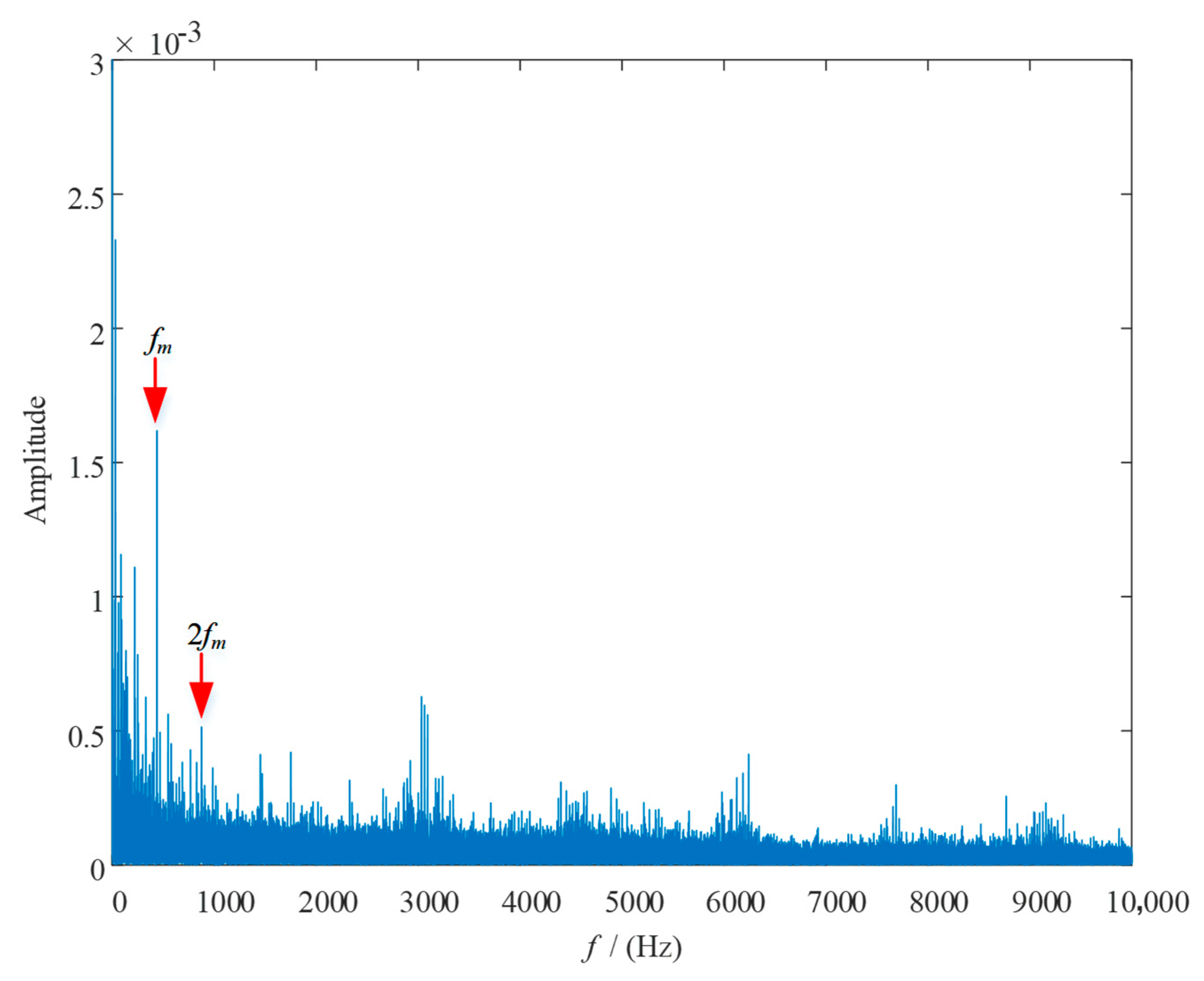
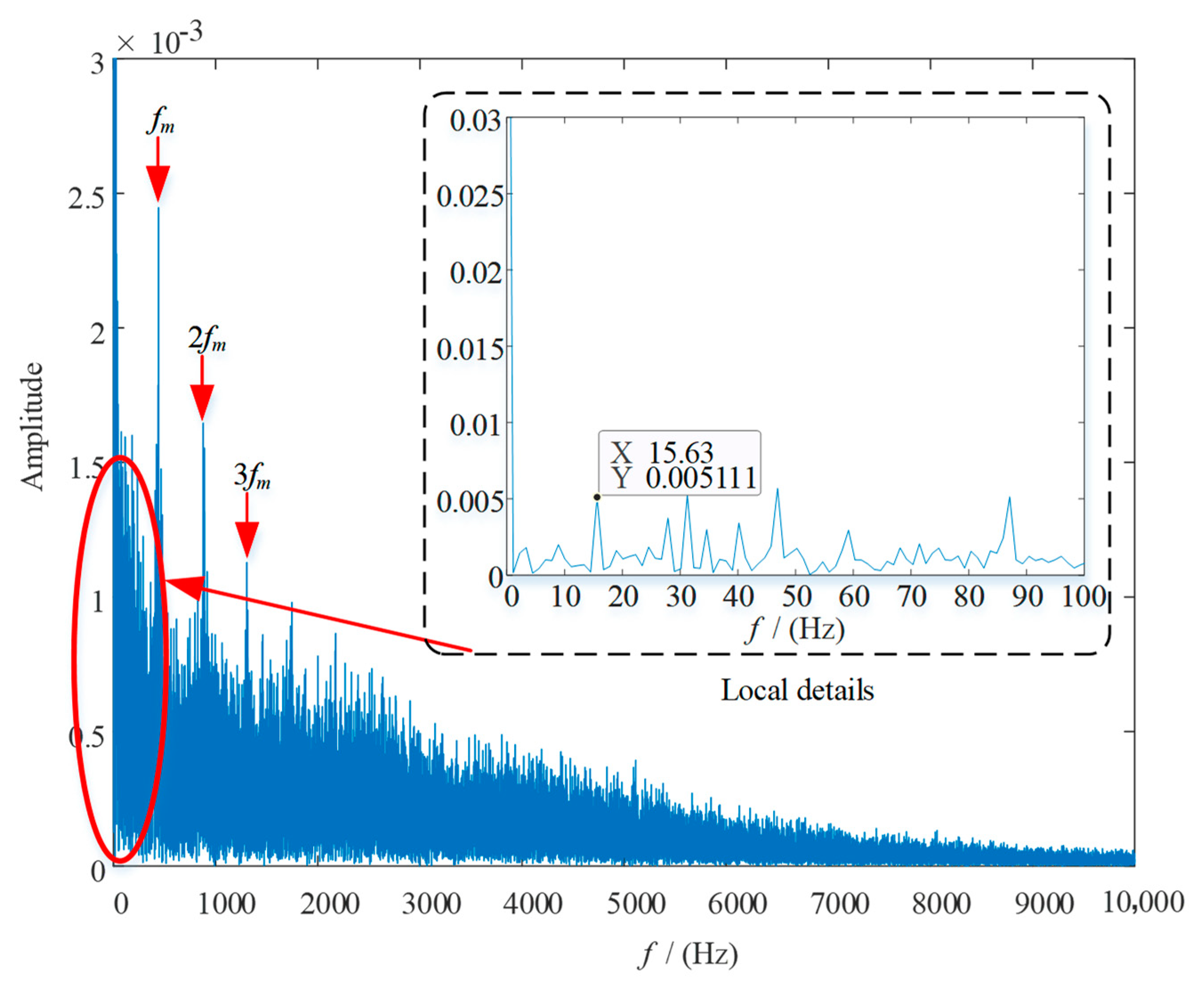
| Rotation frequency (Hz) | fs = 20 | fp = 7.78 | - | fH = 4.38 |
| Fault characteristic frequency (Hz) | N(fs − fH)=15.63 × N | N(fp + fH) = 12.16 × N | - | - |
Publisher’s Note: MDPI stays neutral with regard to jurisdictional claims in published maps and institutional affiliations. |
© 2020 by the authors. Licensee MDPI, Basel, Switzerland. This article is an open access article distributed under the terms and conditions of the Creative Commons Attribution (CC BY) license (http://creativecommons.org/licenses/by/4.0/).
Share and Cite
Shen, J.; Hu, N.; Zhang, L.; Luo, P. Dynamic Analysis of Planetary Gear with Root Crack in Sun Gear Based on Improved Time-Varying Mesh Stiffness. Appl. Sci. 2020, 10, 8379. https://doi.org/10.3390/app10238379
Shen J, Hu N, Zhang L, Luo P. Dynamic Analysis of Planetary Gear with Root Crack in Sun Gear Based on Improved Time-Varying Mesh Stiffness. Applied Sciences. 2020; 10(23):8379. https://doi.org/10.3390/app10238379
Chicago/Turabian StyleShen, Jian, Niaoqing Hu, Lun Zhang, and Peng Luo. 2020. "Dynamic Analysis of Planetary Gear with Root Crack in Sun Gear Based on Improved Time-Varying Mesh Stiffness" Applied Sciences 10, no. 23: 8379. https://doi.org/10.3390/app10238379