Article

Study on Mechanical Properties of the Basalt Fiber-Rubber Granular Concrete under Triaxial Stress Condition and Its Application

1
State Key Laboratory of Geomechanics and Geotechnical Engineering, Institute of Rock and Soil Mechanics, Chinese Academy of Sciences, Wuhan 430071, Hubei, China
2
Geotechnical Engineering, University of Chinese Academy of Sciences, Beijing 100049, China
3
Department of Traffic Engineering, Shandong Transport Vocational College, Taian 271000, Shandong, China
*
Author to whom correspondence should be addressed.
Appl. Sci. 2020, 10(23), 8540; https://doi.org/10.3390/app10238540
Submission received: 12 November 2020 / Revised: 25 November 2020 / Accepted: 27 November 2020 / Published: 29 November 2020

Abstract

:
To reduce the failure probability of rigid supporting structures caused by large deformation of deeply buried high-stress soft rock roadways, the mechanical properties and failure features of basalt fiber-rubber granular concrete (BFRGC) are investigated based on triaxial compression tests. The post-peak strain softening equations of BFRGC, based on the Mohr–Coulomb yield criterion, are deduced and then compiled in the finite-difference software (FLAC3D) to simulate the post-peak strain-softening process of BFRGC. Combined with practical engineering, the supporting effects of BFRGC with different proportions are evaluated by FLAC3D. The results of compression tests show that the yield strength of the BFRGC increases significantly when the mass percentage of basalt fiber is 0.4%. Moreover, mixing basalt fibers into both the plain concrete and rubber concrete can effectively restrain the development of the fractures under three-dimensional stress. The numerical results show that when the mass fractions of basalt fibers and rubber particles are 0.4% and 5–10%, respectively, both the plastic zone in the surrounding rocks and the deformation of the rigid supporting structures decrease obviously. It is indicated that the optimal ratio of BFRGC can effectively reduce the stress concentration around the roadway and improve the overall bearing capacity of the supporting structures.

1. Introduction

With the increase of excavation depths in the coal mine, the mining environment gradually deteriorated, which has brought significant challenges to the stability of surrounding rocks [1,2]. According to the previous studies [3,4], the coal resources with buried depth over 1000 m account for 53% of the total coal resources in China; the excavation length of roadways in the coal mine per year is about 6000 km, and one-tenth of these roadways are high-stress soft rock roadways. In addition, about seventy percent of roadways in deep coal mines had to be repaired and maintained each year [5]. The coal mining depths in Germany, Russia, Japan, and Belgium also generally exceed 1000 m [6,7]. With the constant maturities of support theory, the support materials and measures in roadways have undergone significant changes. The concepts of active and passive support have been widely used in the support system in a coal mine, but nowadays, passive support has become an auxiliary supporting way [8,9,10]. Although great progress has been made in support, efficient support measures are still the weak link in the coal mine.
Rubber granular concrete is a new type of elastic concrete, superior to plain concrete in many aspects [11,12,13]. When rubber granules are mixed into concrete, they can greatly improve the impact resistance and ductility of concrete [14,15]. At present, a great number of researchers have focused on the mechanical properties of rubber concrete. Grinys et al. [16] carried out an experimental study and found that with lower amounts and coarser particle size of crumb rubber, the bending strength decreases, although smaller amounts of crumb rubber demonstrated the best improvement of fracture energy. Gupta et al. [17] reported that the flexural strength of rubber ash concrete decreases with the increase of rubber ash, while the flexural strength of modified concrete is increased with the increase of rubber content. Sukontasukkul et al. [18] studied the properties of concrete pedestrian block mixed with crumb rubber and concluded that rubber particle content has an apparent effect on the concrete performances, and both compressive and flexural strength decreases when the rubber content increase. Li et al. [19] indicated that the failure of rubber powder concrete is ductile compared with plain concrete, and rubber powder concrete pressure-resisting strength decreases with the increase of the rubber powder content. Xu et al. [20] studied fracture behaviors of rubber concrete under cyclic loading and concluded that when rubber content increases, the strength and elastic modulus of rubber concrete decreases, while the fracture energy increases gradually. Other scholars have also studied the mechanical properties and failure mechanisms of rubber concrete [21,22,23,24]. Numerous scholars added some materials into concrete for improving the performance of concrete. Ramírez et al. [25] took mineral wool waste from construction and demolition waste as reinforcement of cement matrices. Wu et al. [26] evaluated the dynamic mechanical properties of fiber-reinforced concrete under different strain rates and concluded that fiber-reinforced concrete with a 0.2% volume content shows much superiority compared to two other kinds of fiber concrete in improving concrete’s mechanical properties. Qin et al. [27] added basalt fibers into rubber concrete and studied the mechanical property of basalt fiber crumb rubber mortars (BF-CRM) based on uniaxial compression tests, and concluded that the uniaxial compressive strength of BF-CRM could be effectively improved by adding basalt fibers.
Since the underground rock masses are in three-dimensional stress in the natural state, it is crucial to conduct triaxial compression tests of basalt fiber crumb rubber mortars for further study. Moreover, the good post-peak performance of basalt fiber crumb rubber mortars in the current numerical research has not been shown. Based on Qin et al.’s research [27], the mechanical properties and failure characteristics of basalt fiber-rubber granular concrete (BFRGC) are studied by triaxial compression tests in the paper. The post-peak strain softening equations of BFRGC with different ratios, based on the Mohr–Coulomb yield criterion, are deduced. Combined with practical engineering, the strain-softening equations are applied to the finite difference method (FLAC3D) to realize the post-peak strain softening process of the supporting materials. The optimal proportions of BFRGC are finally determined by analyzing the results of compression tests and numerical simulation. The triaxial compression tests and numerical simulation further verify the feasibility of BFRGC in supporting deeply buried high-stress soft rock roadways.

2. Compression Tests

2.1. Test Device and Main Materials

The TAW-2000 electrohydraulic servo rock triaxial test machine made by Changchun Chaoyang Test Instrument Factory, Changchun, Jilin province, China, as shown in Figure 1, was adopted to conduct the compression tests.
Rubber particles with a particle size of 6–8 mm and an apparent density of 1200 g·cm3 were used in tests, and their tensile strengths ≥15 MPa. According to previous research [28], when the length of basalt fiber in concrete is about 20 mm, the strength of concrete can be improved significantly. Therefore, the diameter and length of the used basalt fibers in this study were 15 μm and 20 mm, respectively, and the tensile strength and the elastic modulus were 4100–4840 MPa and 90–110 GPa, respectively. The river sands with the maximum particles of 5 mm were chosen in the test, and its fineness modulus was 2.4. The 42.5 ordinary Portland cement was chosen for the experiment, and its physical and mechanical properties were listed in Table 1. The specimens were placed in the incubator where the temperature was about 20 ± 2 °C, and the relative humidity was not less than 95%. The curing durations were 28 days.

2.2. Ratio Design

The mix proportions of BFRGC were designed based on Qin et al. [27] and the “Steel Fiber Concrete Standard Specification” (JGT472-2015) [29]. The results are listed in Table 2. The mass percentage of rubber particles in groups A, B, C, D, and E were about 0%, 5%, 10%, 20%, and 40%, respectively, e.g., group C indicated the mass of rubber particles account for 10% of the total mass of mixtures (cement, river sand, water, water reducer, and binder). The mass fraction of basalt fiber in each group above was divided into 0, 0.4%, 0.8%, and 1.2%, e.g., the C2, indicated the mass of basalt fibers accounted for 0.4% of the total mass of mixtures (rubber granular, cement, river sand, water, water reducer, and binder). The diameter and height of cylinder samples employed in the compression tests were 50 mm and 100 mm, respectively.
According to Table 2, the specimens can be generally divided into four categories: plain concrete (A1), rubber granular concrete (e.g., B1, C1, D1, E1), basalt fiber concrete (e.g., A2, A3, A4), and BFRGC (e.g., B2–B4, C2–C4, D2–D4, E2–E4).

2.3. Triaxial Test Results

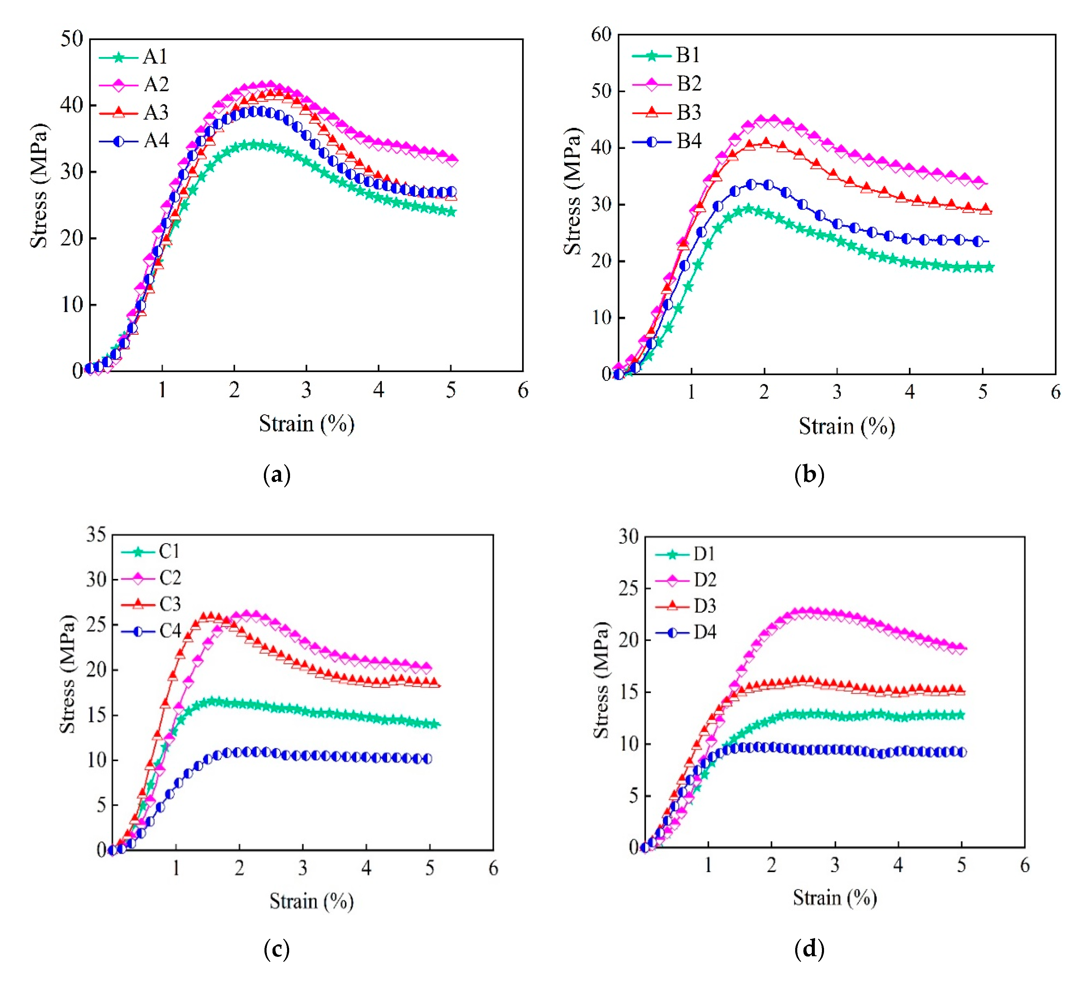
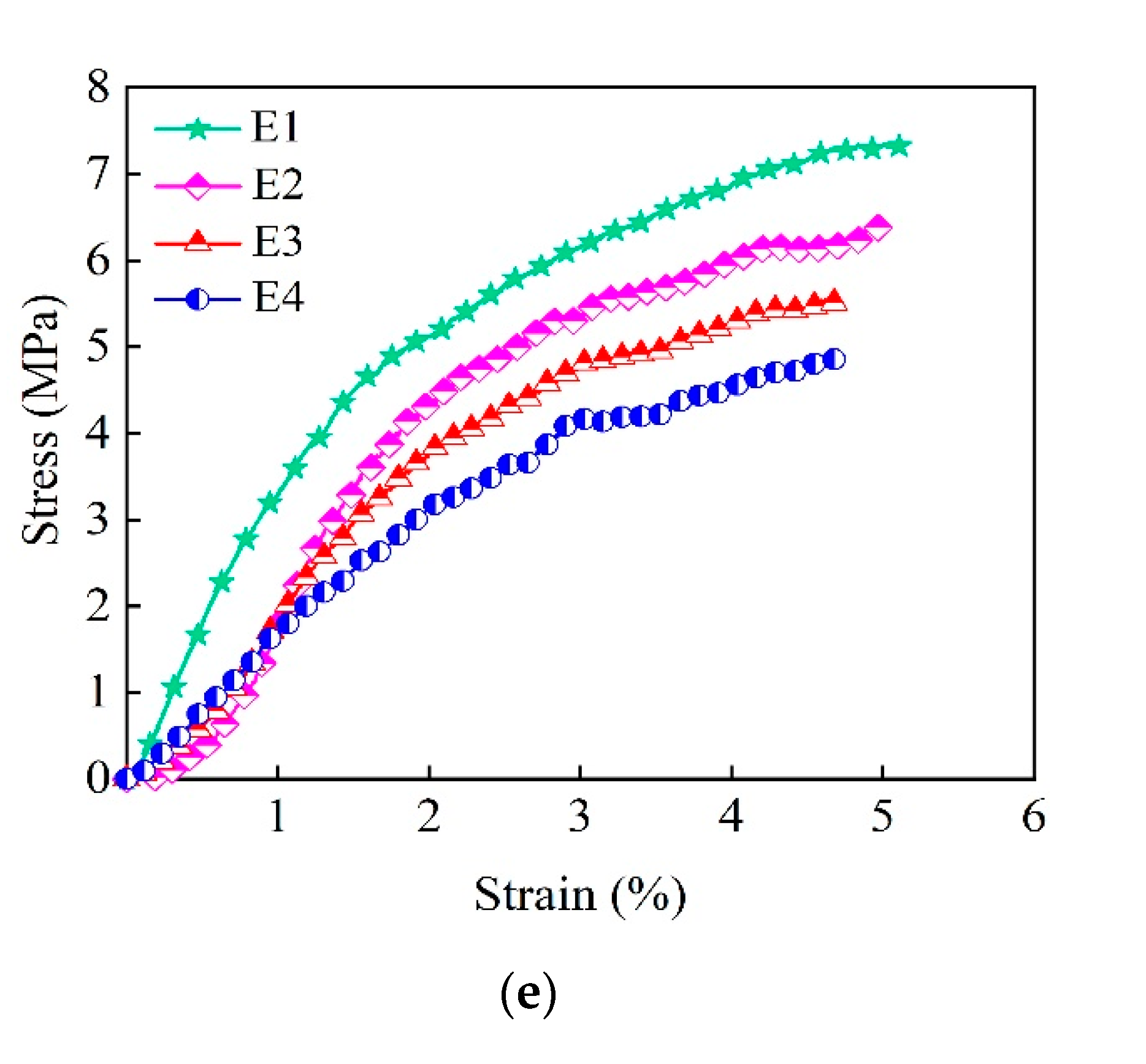
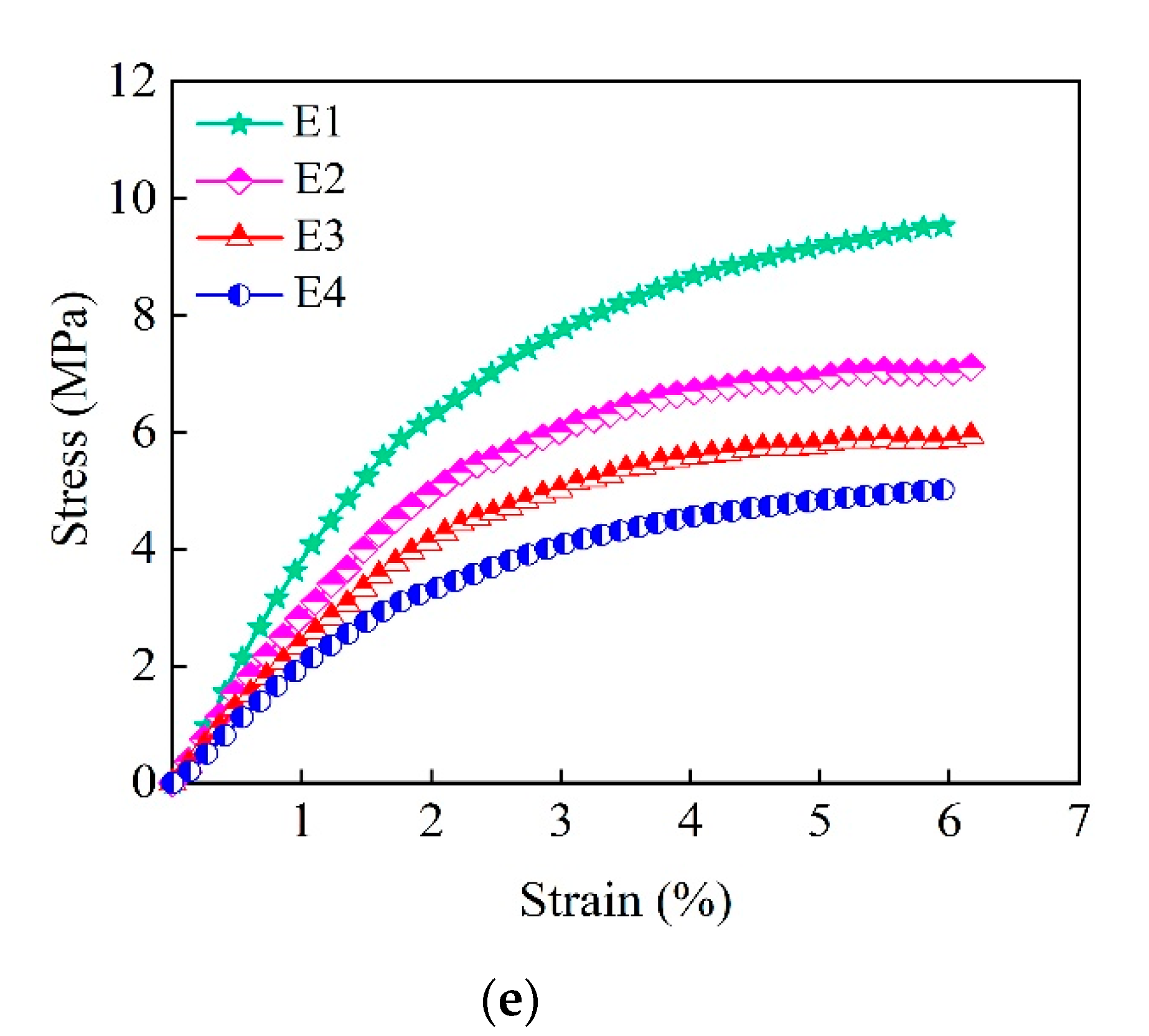
The paper further studied the mechanical properties and failure characteristics of BFRGC under triaxial compression tests with the confining pressures chosen as 5 MPa and 8 MPa. The stress–strain curves under two confining pressures are shown in Figure 2 and Figure 3, respectively.
As shown in Figure 2 and Figure 3, the yield strength increased gradually with increasing confining pressure, as would be expected. For A2, B2, C2, and D2, the yield states appeared when the strains were about 2–2.5%, while there were no peak strengths in group E. A comparison of the stress–strain curves in four groups A, B, C, and D indicated that as rubber particle content increased (from group A to group D), the peak strengths exhibited a noticeable decrease, and the downtrend of stresses after the peak strength became increasingly gentle. In addition, the maximum yield strengths were reached when the mass fraction of basalt fiber was 0.4%, which was consistent with the results of the uniaxial compression test obtained by Qin et al. [27].
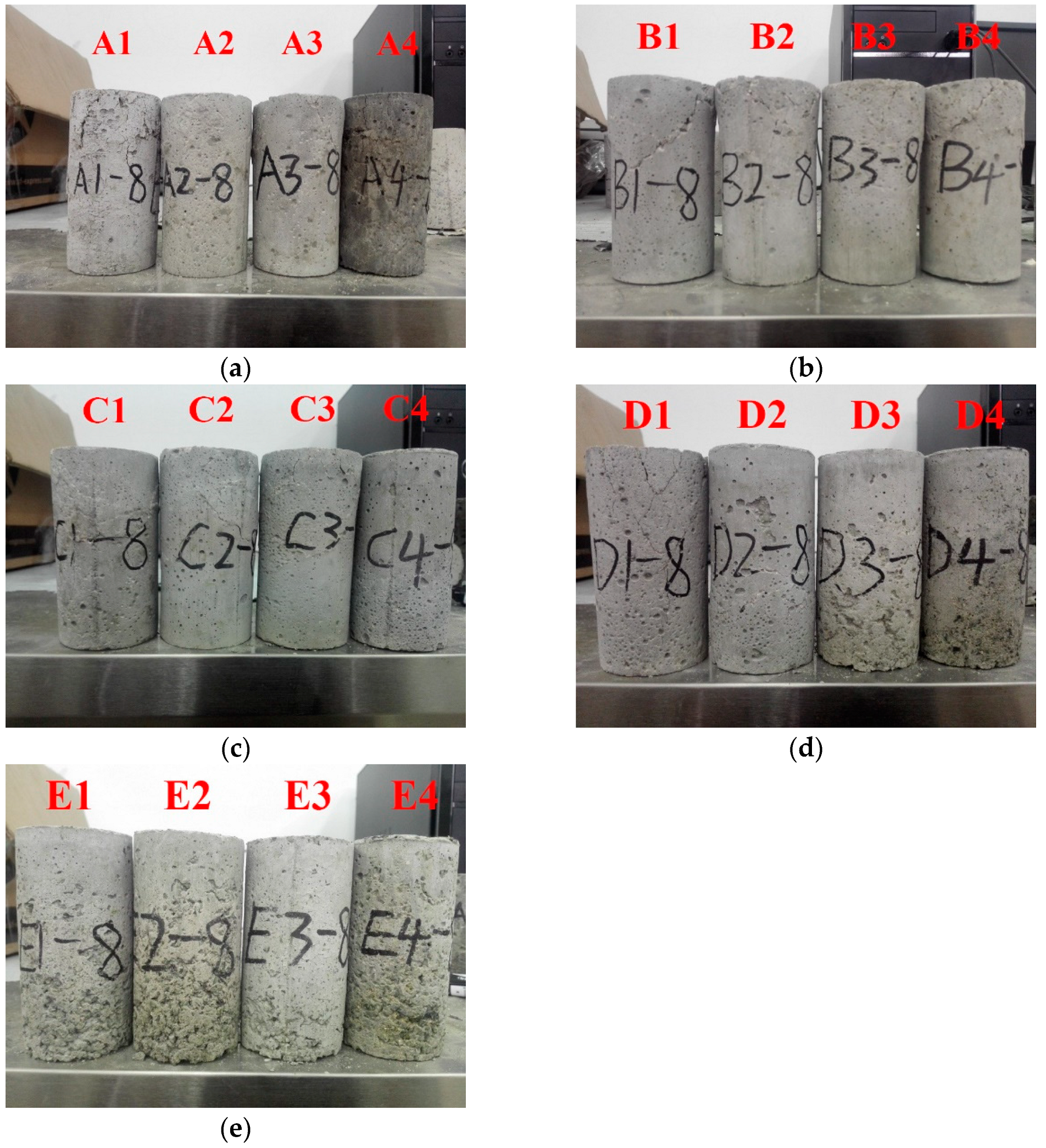
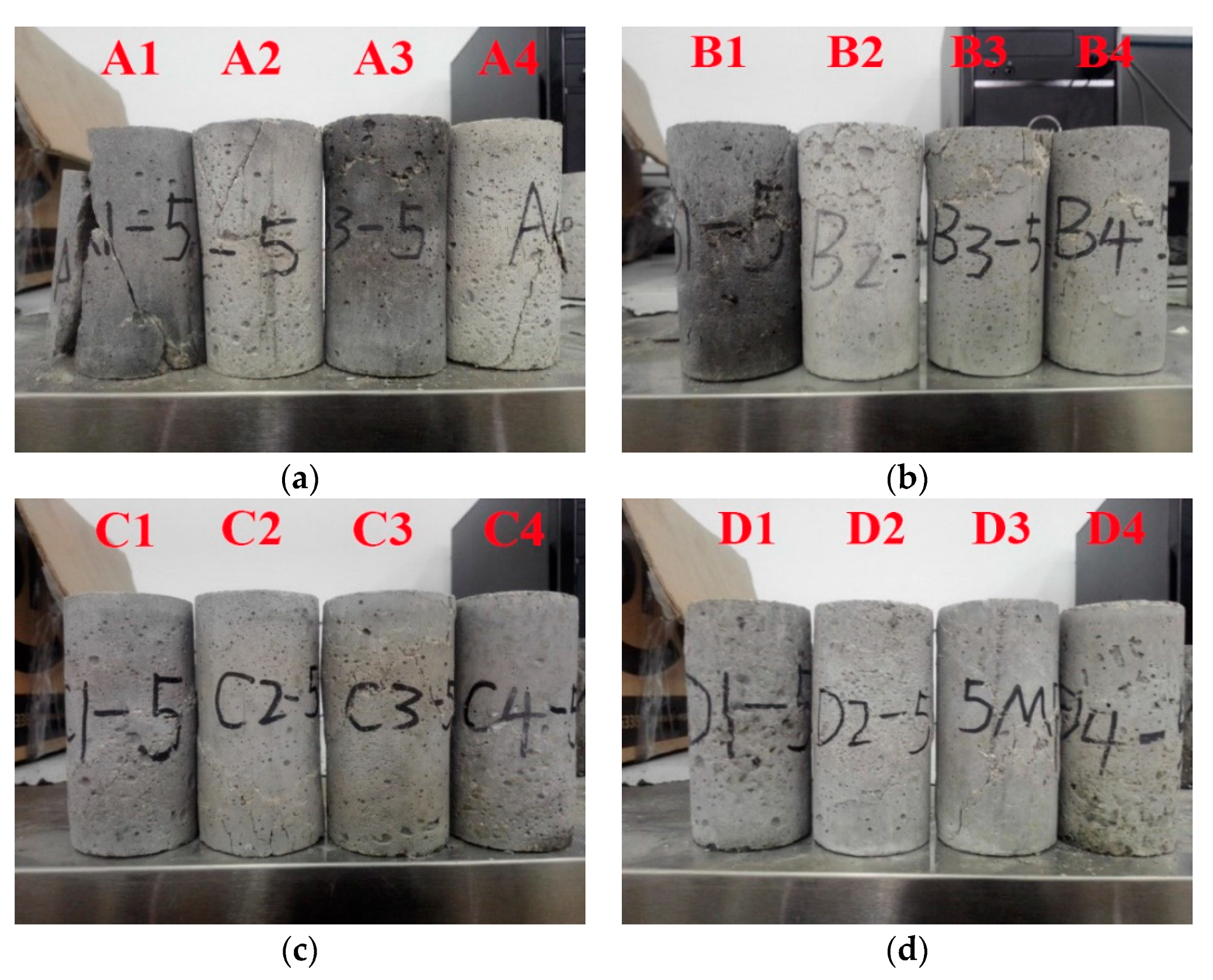
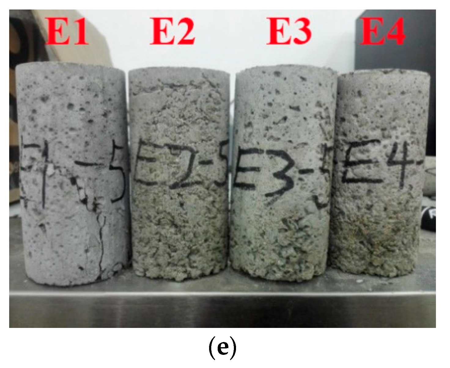
The failure feature of the specimens under 5 MPa and 8 MPa showed some similarities. Only the failure characteristics of the samples under the confining pressure of 5 MPa were analyzed in this paper, as shown in Figure 4. The failures of the specimen under 8 MPa are given in Figure A1.
It can be seen in Figure 4a that the plain concrete (A1) exhibited more serious damage than the basalt fiber concrete (A2, A3, and A4) under the same loading conditions, and its failure mode was the typical split failure, similar to those under uniaxial loading condition. In Figure 4b, the rubber granular concrete B1 was seriously damaged compared to BFRGCs (B2, B3, and B4). Therefore, the addition of basalt fibers could inhibit the development of fractures in both plain concrete and rubber granular concrete, which was consistent with the results under uniaxial compression tests [27]. Moreover, the samples of B2–B4, C2–C4, D2–D4, and E2–E4 had no obvious failure. Thus, the addition of rubber particles and basalt fibers could improve the resistance against the failure of concrete. In general, mixing basalt fibers and rubber granules into concrete could improve concrete performances under three-dimensional stress.

3. Numerical Simulation Results

The finite difference method (FLAC3D) was adopted to evaluate the supporting effect of BFRGC in deep high-stress rock roadways. The following assumptions were made before the numerical simulation:
1.
All the rock materials were assumed to be homogeneous and isotropic;
2.
The mean buried depth for the deeply buried roadways was generally over 800 m; thus, the self-weight of rocks was considered as the vertical stress on the model, and the lateral pressure coefficient was used to simulate the horizontal tectonic force;
3.
The influence of groundwater was not considered.

3.1. The Engineering Overview

The roadway of the central substation of Cixi No.1, Hebei province, China, is a typical deep high-stress soft rock roadway with a buried depth of 850 m. The surrounding rocks are relatively broken, and the deformation of the roadway floor is severe, with a maximum deformation of 500 mm. The rigid supporting structures are frequently destroyed because of the above reasons. The surrounding rocks of the roadway are mainly siltstone, sandy mudstone, and mudstone. The mechanical parameters of the rocks are listed in Table 3. The roadway is excavated in the strata of mudstone, and the cross-section of the roadway is a semicircular arch, with the width and height of 3.8 m and 3.5 m, respectively. The primary supporting materials and parameters are as follows:
1.
High-strength prestressed bolted: diameter and length were 22 mm and 2400 mm, respectively; anchorage length ≥1000 mm; anchorage force ≥150 kN; initial anchorage force ≥50 kN; row spacing and column spacing were 800 mm and 500 mm, respectively.
2.
Plain concrete: the strength and average thickness of concrete were C40 and 400 mm, respectively.

3.2. Numerical Model Setup

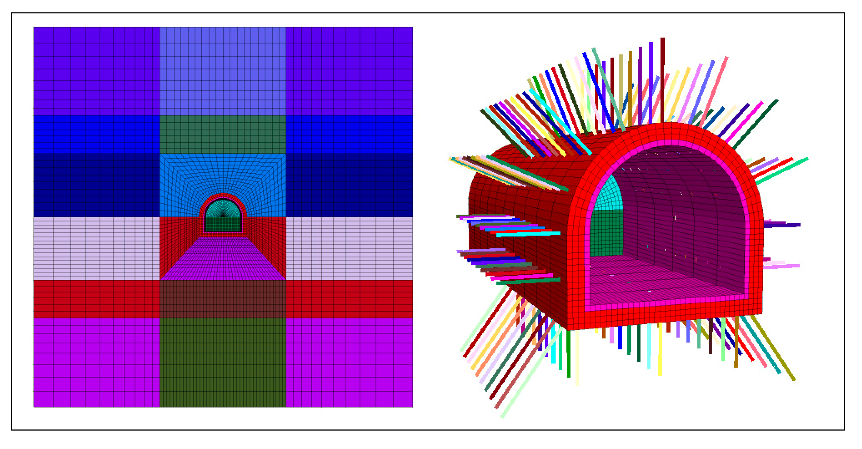
The size of the model had a notable influence on numerical modeling. According to the previous studies [30], the model size of FLAC3D should be at least three times larger than that of the field project, and the relative error of the calculated results was about 5%; while the model size was five times larger than that of the prototype, and the relative error was about 1%. The adopted model size was five times larger than the prototype size in this study. The length, width, and height of the model were 30 m × 20 m × 30 m, respectively. The vertical stress of 23.8 MPa was applied to the upper boundary to simulate the overburden rocks. The lateral pressure coefficient was adopted as 1.3 to simulate the horizontal tectonic stress. The model was run to equilibrium to generate the initial stress before the roadway was excavated.
In the numerical simulation, the built-in cable unit was adopted to simulate the bolt materials, and the zone unit was adopted to simulate the concrete. The rock materials were assumed to be an elastoplastic model, which obeys the Mohr–Coulomb yield criterion. The model and the supporting structures are shown in Figure 5.

3.3. Realization of Strain-Softening

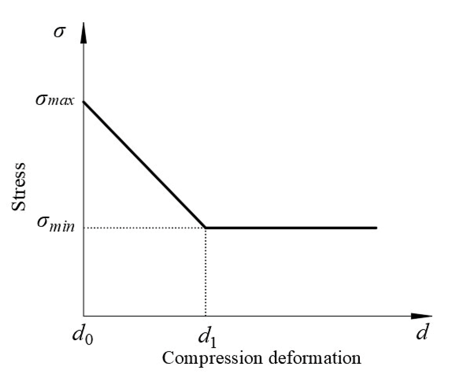
In the current numerical simulation studies, the post-peak strain softening process of supporting materials, based on the Mohr–Coulomb yield criterion, was rarely considered. Therefore, some discrepancies may exist between numerical modeling and field monitoring. The linear strain-softening equation of the supporting materials was herein deduced based on previous studies [31,32,33]. The following assumption was made before the equation was derived: the supporting materials were in unidirectional stress during the supporting process. The linear strain-softening equation was constructed in the form of Figure 6.
A general equation can be developed from Figure 6 and shown as follows in Equation (1).
σ = { σ min σ max d 1 d 0 d + σ max σ min σ max d 1 d 0 d 0 ,   d 0 d < d 1 σ min ,   d d 1
where σmax and σmin are the yield stress and the residual stress, respectively; d0 and d1 are displacements corresponding to the yield stress and the residual stress, respectively, and d is the compressive displacement.
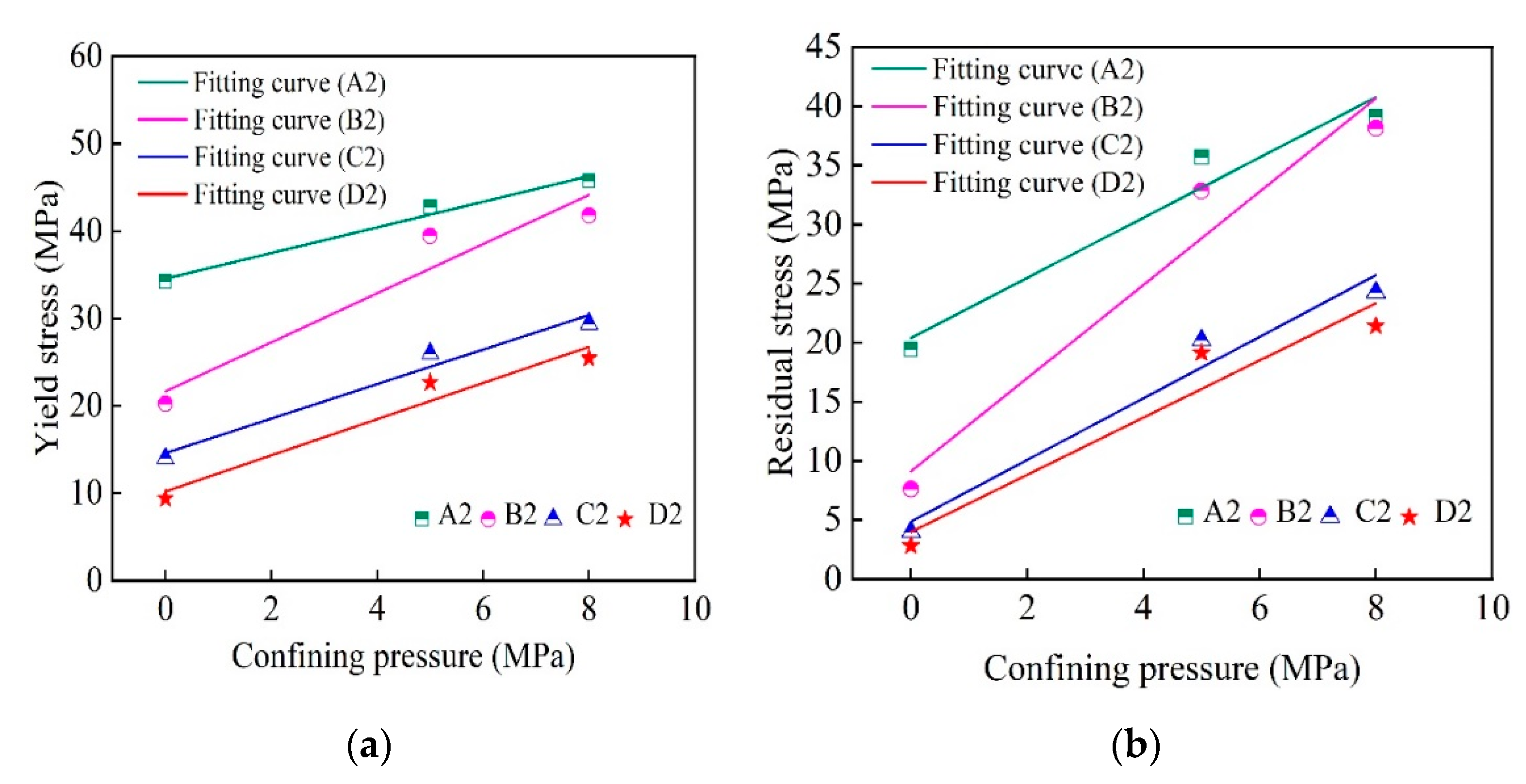
Based on the results of the above compression test, the optimum content of basalt fibers in BFRGC was 0.4%; therefore, A2, B2, C2, and D2 were selected to further study the optimal mixing amounts of rubber particles. The σmax and σmin in Equation (1) are determined by fitting the results of the above triaxial test and the uniaxial test obtained by Qin et al. [27]. The relationships between confining pressure and yield stress and residual stress are shown in Figure 7, and the corresponding fitting equations are listed in Equation (2).
{ σ y _ A 2 = 34.55 + 1.47 σ 3 , σ r _ A 2 = 20.40 + 2.54 σ 3 σ y _ B 2 = 21.64 + 2.81 σ 3 , σ r _ B 2 = 9.11 + 3.94 σ 3 σ y _ C 2 = 14.58 + 1.98 σ 3 , σ r _ C 2 = 4.86 + 2.61 σ 3 σ y _ D 2 = 10.19 + 2.07 σ 3 , σ r _ D 2 = 3.98 + 2.42 σ 3
where σy is the yield stress, MPa; σ3 is the confining pressure, MPa; σr is the residual stress, MPa.
It could be determined from Equation (2) that the yield stresses of A2, B2, C2, and D2 under the uniaxial stress were about 34.55 MPa, 21.64 MPa, 14.58 MPa, and 10.19 MPa, and the residual strengths were about 20.40 MPa, 9.11 MPa, 4.86 MPa, and 3.98 MPa, respectively. Additionally, based on the uniaxial test results [27], the d0 of A2, B2, C2, and D2 under the uniaxial stress was about 0.23 mm, 0.53 mm, 0.64 mm, and 0.82 mm, and the d1 was about 0.46 mm, 1.05 mm, 1.27 mm, and 1.63 mm. The derived equations of A2, B2, C2, and D2 are thus given in Equations (3)–(6), respectively.
σ A 2 = { 48.70 61.52 d ,   0.23 d < 0.46 20.40 ,   d 0.46
σ B 2 = { 34.41 24.10 d ,   0.53 d < 1.05 9.11 ,   d 1.05
σ C 2 = { 24.45 15.43 d ,   0.64 d < 1.27 4.86 ,   d 1.27
σ D 2 = { 16.48 7.67 d ,   0.82 d < 1.63 3.98 ,   d 1.63
The Fish function in FLAC3D was carried out to realize the post-peak strain-softening process of the supporting materials. The cohesion c and internal friction angle φ were refreshed within a certain time-step according to the current relative displacement in the supporting structures. The cohesion ci and internal friction angle φi can be computed from Equation (7) when the relative displacement is d.
{ c i = σ σ max × c 0 φ i = arctan ( σ σ max × tan φ 0 )
where σ is the stress obtained from Equations (3)–(6) when the relative displacement in supporting structures is d; σmax is the yield stress; c0 is the initial cohesion, and φ0 is the initial internal friction angle.

3.4. Analysis of Numerical Results

A2, B2, C2, D2, and plain concrete (PC) were chosen as the supporting materials of the roadway, and their physical and mechanical parameters are listed in Table 4. The distribution characteristics of the plastic zone in the surrounding rocks and the deformations in the rigid support structures were evaluated under different supporting materials. Five cases with different supporting materials were considered, and the specific supporting ways were as follows: after the 5 m excavation, at the vicinity of the rock wall, the supporting material of 300 mm thickness was first, poured and served as the internal supporting structure, and then followed by the PC of 100 mm thickness as the outer rigid supporting structure. The supporting schemes are listed in Table 5. The stress–displacement curve of the PC under the uniaxial test is shown in Figure 8, and the strain-softening equation of PC is given in Equation (8). It is worth noting that, due to the need to consider the strain-softening process of supporting materials, the PC adopted in the numerical simulation was A1, instead of C40 concrete. Moreover, in this study, because the proportion of PC was not optimal, the uniaxial compressive strength of PC was only 15.43 MPa, and the elasticity modulus of the PC given in Table 4 was low compared to that of the normal weight concrete. However, the outer rigid supporting materials in all cases were the same PC, so the lower elasticity modulus of the PC almost did not affect the comparison among different cases.
σ p = { 20.98 12.33 d ,   0.45 d < 0.85 8.65 ,   d 0.85

3.4.1. Plastic Zone Analysis

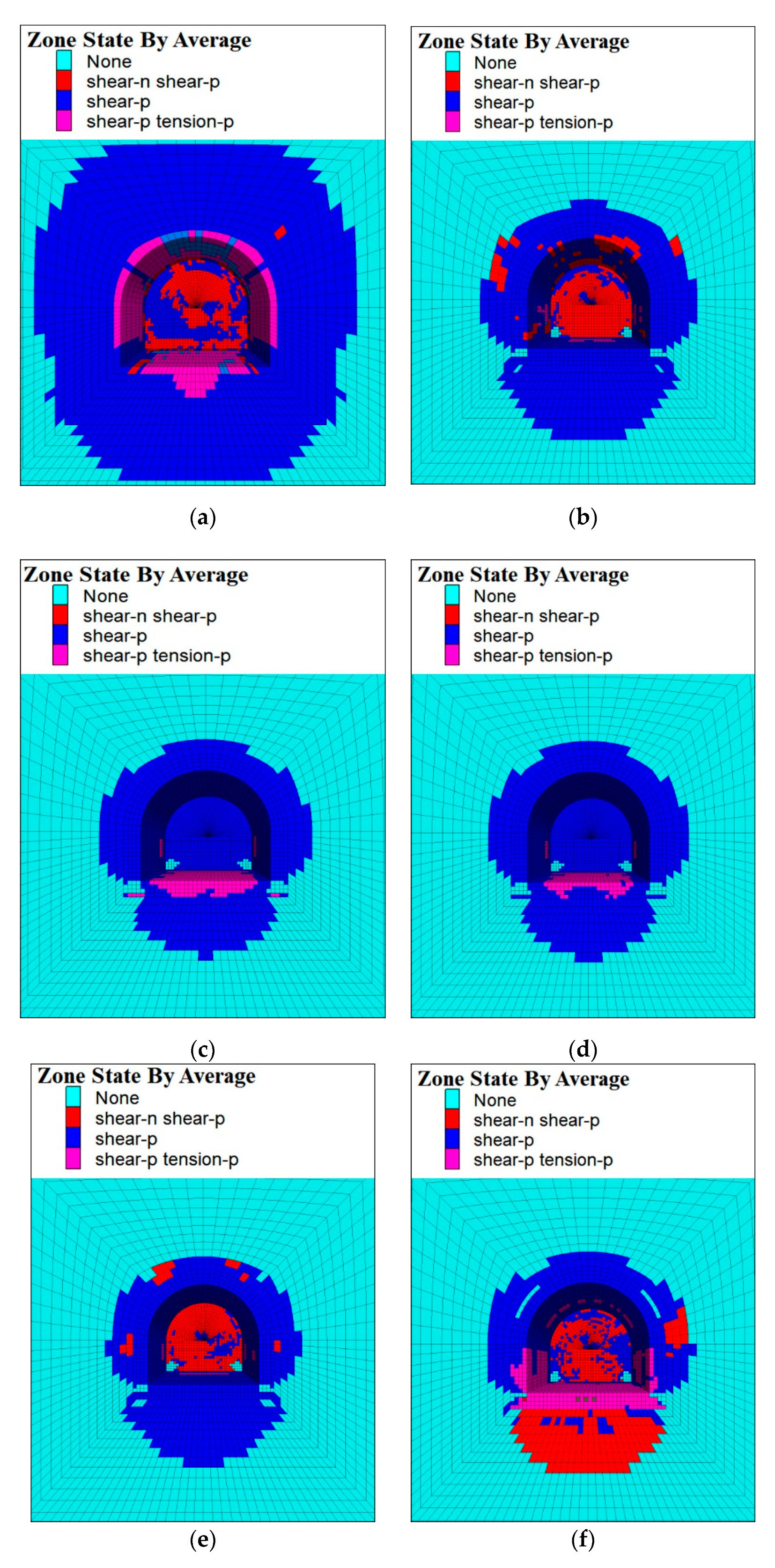
It is worth noting that the bolts were herein adopted together with the concrete for supporting the roadway. The plastic region in the surrounding rocks had evident discrepancies under different supporting schemes. The distribution of the plastic zone is shown in Figure 9.
As shown in Figure 9, the plastic zone in the surrounding rocks under unsupported conditions (Case 1) was more extensive compared to other cases with support, and its range may approximately extend to 3 m, and the roof and floor of the roadway had exhibited some damaged area. It was found from Case 2 to Case 6 that the maximum extension of the plastic zone in Case 2, Case 3, Case 4, Case 5, and Case 6 was about 1.82 m, 1.42 m, 1.41 m, 1.73 m, and 1.96 m, respectively. The plastic zones of Case 3 and Case 4 were smaller compared with those of other cases; therefore, when the mass fractions of basalt fibers and rubber particles in BFRGC were 0.4% and 5–10%, respectively, the BFRGC could effectively reduce the plastic zone of surrounding rock of deep high-stress soft rock roadways, achieving the optimal performance.

3.4.2. Displacement Analysis

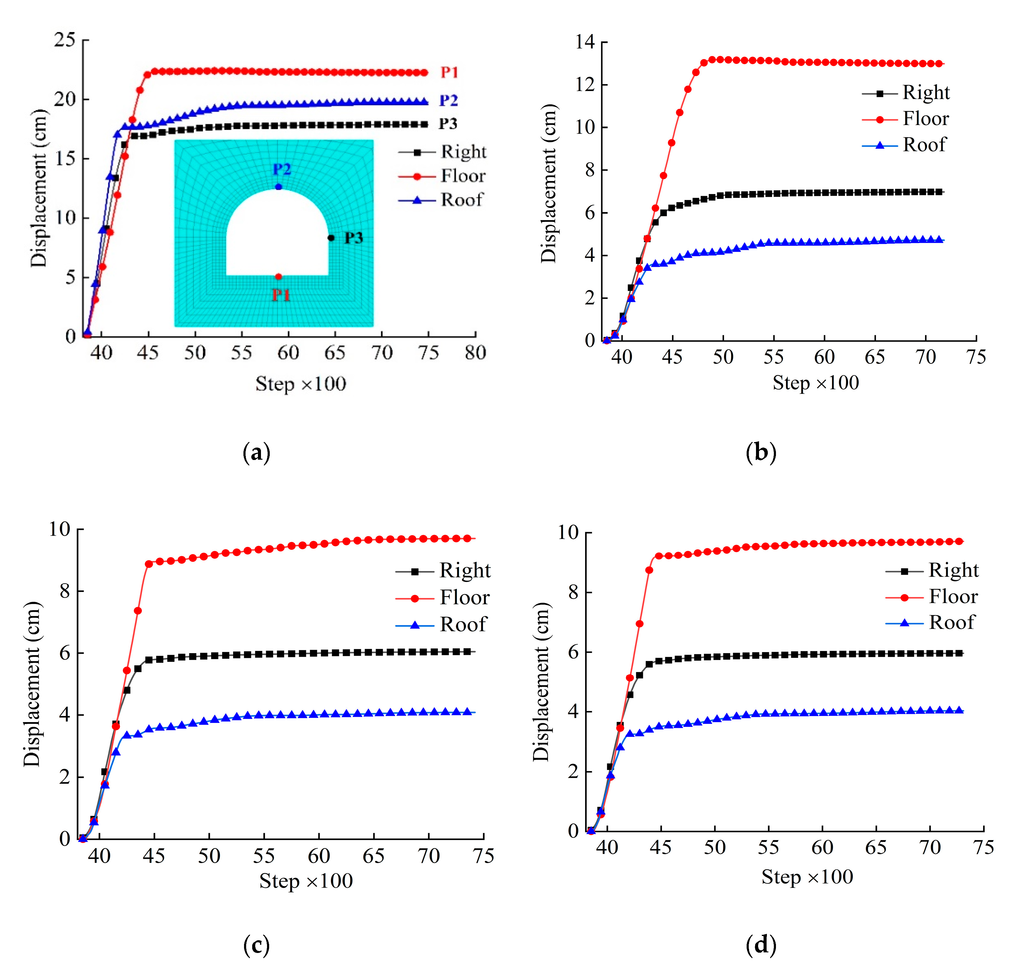
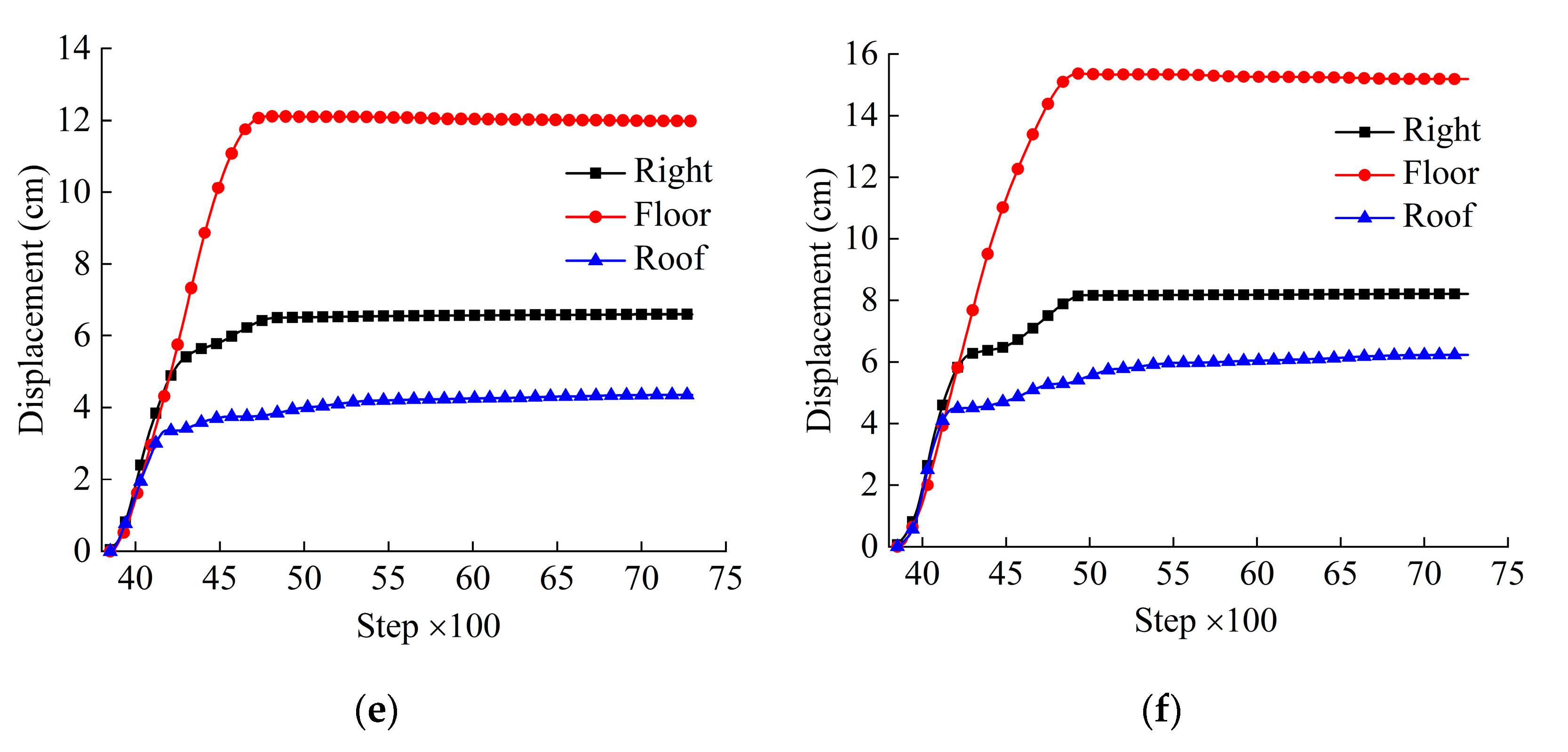
Displacements in the outer rigid supporting structures were recorded in the numerical calculation to study whether BFRGC could reduce the deformation of the outer rigid supporting structures. As shown in Figure 10a, the monitored points were located on the right side, the floor, and the roof of the roadway. It is noteworthy that the monitored displacements in Case 1 were the deformation of the surrounding rocks of the roadway rather than that of the supporting structures. The displacement history curves monitored under the various supporting schemes are shown in Figure 10.
It can be observed from Figure 10 that under the supporting conditions, the displacement of the monitoring points for five cases had consistent features in some aspects, e.g., the deformation of the roadway floor was the largest, followed by the right side of the roadway, and then the roadway roof, which explains the reason why the deformation of the roadway floor in Cixi No.1 was so severe. When the numerical calculation reaches the equilibrium state, the major deformation of the roadway was located at the floor, and the maximum deformation was up to 22.40 cm under unsupported condition. The maximum displacements at the floor were about 13.17 cm, 9.70 cm, 9.69 cm, 12.11 cm, and 15.36 cm, respectively, under the supporting ways of Case 2, Case 3, Case 4, Case 5, and Case 6. The deformations of the roadway in Case 3 and Case 4 were obviously smaller compared with other cases. Therefore, it could be concluded that when the mass fraction of basalt fibers and rubber particles in BFRGC was 0.4% and 5–10%, respectively, the BFRGC could effectively control the deformation in the rigid supporting structures. Additionally, the slight difference of the deformations at the floor among different cases was partially due to the small support thickness of concrete.
By extracting the displacement from four monitoring lines arranged at the roof, floor, and sides, respectively, the displacement curves of the roadway at different depths with different support schemes are shown in Figure 11. It can be seen that under the support of the BFRGC with the optimum ratios, the maximum deformations at four monitoring lines were limited at approximately 10 cm, and the floor heave was controlled effectively.

4. Conclusions

There is no doubt that the mechanical properties of the supporting materials play a critical role in supporting deep high-stress soft rock roadways. The mechanical properties and failure characteristics of basalt fiber-rubber granular concrete (BFRGC) are studied based on the triaxial compression tests. The supporting effects of the BFRGC with different ratios in the field application are further investigated using the finite difference method. The optimum content of basalt fibers and rubber particles in BFRGC is determined based on the results of triaxial compression tests and numerical simulation. The linear strain-softening equations of the BFRGC are deduced and then compiled in the finite-difference software to effectively simulate its post-peak strain-softening process. Therefore, the computed results are more reasonable compared with that without considering the strain-softening of supporting materials. Some main conclusions were reached and are listed below:
1.
The maximal yield strength of the BFRGC under triaxial compression tests is obtained when the mass fraction of basalt fiber in BFRGC is 0.4%. Additionally, basalt fiber can inhibit the development of fractures in plain concrete and rubber concrete, and mixing rubber particles into plain concrete can also inhibit the development of fractures of concrete.
2.
Compared with the stress–strain curves of plain concrete under triaxial compression tests, the decreasing trend of BFRGC after the peak strength is increasing gentle, it is illustrated that the BFRGC has a good post-peak performance.
3.
The optimum contents of basalt fibers and rubber particles in BFRGC are 0.4% and 5–10%, respectively, and the BFRGC with optimum ratios can effectively reduce the plastic region in surrounding rock of roadways and deformation of the rigid supporting structures. It may provide technical guidance for the support of deeply buried high-stress soft rock roadways.
4.
The slight difference of the deformations among different supporting ways obtained by the finite difference method is partially due to the small support thickness of concrete. It is expected that the difference will be greater and that the advantage of the BFRGC with optimum proportions will become more obvious if the support thickness is increased.

Author Contributions

Conceptualization, D.W. and Z.L.; methodology, D.W.; software, D.W., J.L. and H.S.; validation, D.W., B.P. and Z.L.; formal analysis, D.W. and Z.L.; investigation, D.W. and J.L.; data curation, D.W. and H.S.; writing—original draft preparation, D.W.; writing—review and editing, D.W. All authors have read and agreed to the published version of the manuscript.

Funding

This research received no external funding.

Conflicts of Interest

The authors declare no conflict of interest.

Appendix A

Figure A1. Failure modes of the specimens under 8 Mpa. (a) Group A; (b) group B; (c) group C; (d) group D; (e) group E.
Applsci 10 08540 g0a1

References

  1. Jiang, Y.D.; Pan, Y.S.; Jiang, F.X.; Don, L.M. State of the art review on mechanism and prevention of coal bumps in China. J. China Coal Soc. 2014, 39, 205–213. [Google Scholar] [CrossRef]
  2. He, M.C.; Xie, H.P.; Peng, S.P. Study on rock mechanics in deep mining engineering. Chin. J. Rock Mech. Eng. 2005, 24, 2803–2813. [Google Scholar] [CrossRef]
  3. Xie, H.P.; Gao, F.; Ju, Y. Research and development of rock mechanics in deep ground engineering. Chin. J. Rock Mech. Eng. 2015, 34, 2161–2178. [Google Scholar] [CrossRef]
  4. Hu, Z.Q.; Xiao, W.; Wang, P.J.; Zhao, Y.L. Concurrent mining and reclamation for underground coal mining. J. China Coal Soc. 2013, 38, 301–307. [Google Scholar] [CrossRef]
  5. Zhou, Y. Research on Hongmiao mine united timbering of soft rock coal roadway under high stress. Master’s Thesis, Liaoning Technical University, Fuxin, Liaoning, China, 2005. [Google Scholar]
  6. Hu, S.R.; Peng, J.C.; Huang, C.; Can, P.; Li, M. An overview of current status and progress in coal mining of the deep over a kilometer. J. China Coal Soc. 2011, 20, 105–110. [Google Scholar] [CrossRef]
  7. Vogel, M.; Rast, H.P. AlpTransit-safety in construction as a challenge: Health and safety aspects in very deep tunnel construction. Tunn. Undergr. Space Technol. 2000, 15, 481–484. [Google Scholar] [CrossRef]
  8. Gao, M.S.; He, Y.L.; Lu, C.P. Coordination mechanism of internal strong active support, soft structure pressure relief and anti-punching of roadway. J. China Coal Soc. 2020, 45, 2749–2759. [Google Scholar] [CrossRef]
  9. Yu, F.H.; Zhao, T.B.; Tan, Y.L.; Guo, W. Study on quantitative calculation method of mining roadway supporting intensity under depressurized mining. J. Min. Saf. Eng. 2016, 33, 460–466. [Google Scholar] [CrossRef]
  10. He, M.C.; Li, C.; Gong, W.L.; Jiang, C. Support principles of NPR bolts /cables and control techniques of large deformation. Chin. J. Rock Mech. Eng. 2016, 35, 1513–1529. [Google Scholar] [CrossRef]
  11. Kaewunruen, S.; Li, D.; Chen, Y.; Xiang, Z. Enhancement of dynamic damping in eco -friendly railway concrete sleepers using waste-tyre crumb rubber. Materials 2018, 11, 1169. [Google Scholar] [CrossRef] [Green Version]
  12. Cao, G.R.; Wang, J.; Qing, L.B.; Yang, Z. Experimental study on the fracture characteristics of crumb rubber concrete. J. Civ. Archit. Environ. Eng. 2018, 40, 91–97. [Google Scholar] [CrossRef]
  13. Al-Tayeb, M.M.; Abu Bakar, B.H.; Ismail, H.; Md Akil, H. Effect of partial replacement of sand by recycled fine crumb rubber on the performance of hybrid rubberized-normal concrete under impact load: Experiment and simulation. J. Clean. Prod. 2013, 59, 284–289. [Google Scholar] [CrossRef]
  14. Atahan, A.O.; Yücel, A.Ö. Crumb rubber in concrete: Static and dynamic evaluation. Constr. Build. Mater. 2012, 36, 617–622. [Google Scholar] [CrossRef]
  15. Ganesan, N.; Bharati Raj, J.; Shashikala, A.P. Flexural fatigue behavior of self-compacting rubberized concrete. Constr. Build. Mater. 2013, 44, 7–14. [Google Scholar] [CrossRef]
  16. Grinys, A.; Sivilevičius, H.; Pupeikis, D.; Ivanauskas, E. Fracture of concrete containing crumb rubber. J. Civ. Eng. Manag. 2013, 19, 447–455. [Google Scholar] [CrossRef] [Green Version]
  17. Gupta, T.; Chaudhary, S.; Sharma, R.K. Assessment of mechanical and durability properties of concrete containing waste rubber tire as fine aggregate. Constr. Build. Mater. 2014, 73, 562–574. [Google Scholar] [CrossRef]
  18. Sukontasukkul, P.; Chaikaew, C. Properties of concrete pedestrian block mixed with crumb rubber. Constr. Build. Mater. 2006, 20, 450–457. [Google Scholar] [CrossRef]
  19. Li, Z.C.; Xu, J.Y.; Luo, X.; Fan, J.S.; Miao, H.D. Experimental study on the basic mechanical properties of rubber powder concrete. Bull. Chin. Ceram. Soc. 2013, 32, 2589–2594. [Google Scholar] [CrossRef]
  20. Xu, Y.; Bu, J.W.; Liu, Y.X.; Xu, Y.C. Fracture behaviors of rubber concrete under cyclic loading. J. Civ. Environ. Eng. 2020. [Google Scholar] [CrossRef]
  21. Mohammed, B.S.; Adamu, M.; Shafiq, N. A Review on the Effect of Crumb Rubber on the Properties of Rubbercrete. Int. J. Civ. Eng. Technol. 2017, 8, 599–615. Available online: http://www.iaeme.com/IJCIET/issues.asp?JType=IJCIET&VType=8&IType=9 (accessed on 15 September 2020).
  22. Thomas, B.S.; Gupta, R.C.; Panicker, V.J. Recycling of waste tire rubber as aggregate in concrete: Durability-related performance. J. Clean. Prod. 2016, 112, 504–513. [Google Scholar] [CrossRef]
  23. Richardson, A.; Coventry, K.; Edmondson, V.; Dias, E. Crumb rubber used in concrete to provide freeze-thaw protection (optimal particle size). J. Clean. Prod. 2016, 112, 599–606. [Google Scholar] [CrossRef]
  24. Ataei, H. Experimental study of rubber tire aggregates effect on compressive and dynamic load-bearing properties of cylindrical concrete specimens. J. Mater. Cycles Waste Manag. 2016, 18, 665–676. [Google Scholar] [CrossRef]
  25. Ramírez, C.P.; Merino, M.D.R.; Arrebola, C.V.; Barriguete, A.V.; Kosior-Kazberuk, M. Analysis of the mechanical behaviour of the cement mortars with additives of mineral wool fibres from recycling of CDW. Constr. Build. Mater. 2019, 210, 56–62. [Google Scholar] [CrossRef]
  26. Wu, Y.; Song, W.; Zhao, W.; Tan, X. An experimental study on dynamic mechanical properties of Fiber-Reinforced concrete under different strain rates. Appl. Sci. 2018, 8, 1904. [Google Scholar] [CrossRef] [Green Version]
  27. Qin, J.-L.; Qiao, W.-G.; Lin, D.-G.; Zhang, S.; Wang, J.-Y. Mechanical Properties and Numerical Analyses of Basalt Fiber Crumb Rubber Mortars in Soft Rock Roadways. Adv. Civ. Eng. 2019, 2019, 1–13. [Google Scholar] [CrossRef] [Green Version]
  28. Gao, Y. Study on basic mechanical properties of basalt fiber recycled concrete. Master’s Thesis, Anhui University of Science and Technology, Huainan, Anhui, China, 2018. [Google Scholar]
  29. Lin, X.S.; Yang, G.L. Steel Fiber High-Strength and Ultra-High-Strength Concrete; Science Press: Beijing, China, 2002; pp. 27–35. [Google Scholar]
  30. Xu, G.C.; Bai, H.C.; Zheng, Y.R.; Liu, C. Supporting Structure of Underground Engineering; China Water Resource Hydropower Press: Beijing, China, 2002. [Google Scholar]
  31. Voisin, C.; Ionescu, I.; Campillo, M. Crack growth resistance and dynamic rupture arrest under slip-dependent friction. Phys. Earth Planet. Inter. 2002, 131, 279–294. [Google Scholar] [CrossRef]
  32. Ampuero, J.-P.; Vilotte, J.-P.; Sa´nchez-Sesma, F.J. Nucleation of rupture under slip dependent friction law: Simple models of fault zone. J. Geophys. Res. 2002, 107. [Google Scholar] [CrossRef] [Green Version]
  33. Li, W.T.; Li, S.C.; Feng, X.D.; Li, S.C.; Yuan, C. Study of post-peak strain softening mechanical properties of rock based on Mohr-Coulomb criterion. Chin. J. Rock Mech. Eng. 2011, 30, 1460–1466. [Google Scholar]
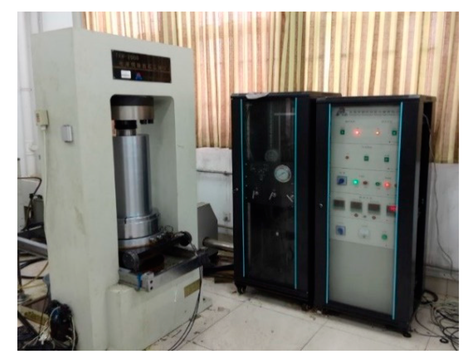
Figure 1. TAW-2000 triaxial test machine.
Applsci 10 08540 g001
Figure 2. Test results under confining pressure of 5 Mpa. (a) Group A; (b) group B; (c) group C; (d) group D; (e) group E.
Applsci 10 08540 g002aApplsci 10 08540 g002b
Figure 3. Test results under confining pressure of 8 Mpa. (a) Group A; (b) group B; (c) group C; (d) group D; (e) group E.
Applsci 10 08540 g003aApplsci 10 08540 g003b
Figure 4. Failure modes of the specimens under 5 Mpa. (a) Group A; (b) group B; (c) group C; (d) group D; (e) group E.
Applsci 10 08540 g004aApplsci 10 08540 g004b
Figure 5. Model setup and supporting structures of the roadway.
Applsci 10 08540 g005
Figure 6. The linear strain-softening equation.
Applsci 10 08540 g006
Figure 7. The fitting results. (a) The relationships between confining pressure and yield stress; (b) the relationships between confining pressure and residual stress.
Applsci 10 08540 g007
Figure 8. The stress–displacement curve of PC under uniaxial tests.
Applsci 10 08540 g008
Figure 9. Plastic zone distribution of six cases. (a) case 1; (b) case 2; (c) case 3; (d) case 4; (e) case 5; (f) case 6.
Applsci 10 08540 g009
Figure 10. Recorded displacements for different cases. (a) Case 1; (b) case 2; (c) case 3; (d) case 4; (e) case 5; (f) case 6.
Applsci 10 08540 g010aApplsci 10 08540 g010b
Figure 11. Controlling the effect of the basalt fiber-rubber granular concrete (BFRGC) with the optimum ratios in the surrounding rocks along the roadway.
Applsci 10 08540 g011
Table 1. Physical and mechanical properties of the cement.
Specific Surface Area (cm2·g−1)Density (g·cm3)Compressive Strength (MPa)Bending Strength (MPa)
3 Days28 Days3 Days28 Days
34503.0022.048.56.09.2
Table 2. The mix proportions of the concrete.
GroupRubber Particles (%)Basalt Fibers (%)Basalt Fiber (kg·m3)Rubber Granular (kg·m3)Cement (kg·m3)River Sand (kg·m3)Water (kg·m3)Water Reducer (kg·m3)Binder (kg·m3)
AA10%000380701335.70
A20.4%2.350380701335.70
A30.8%4.700380701335.70
A41.2%7.060380701335.70
BB15%0057.763805701335.78.66
B20.4%4.6457.763805701335.78.66
B30.8%9.3257.763805701335.78.66
B41.2%14.0357.763805701335.78.66
CC110%00123.023805701335.718.45
C20.4%4.94123.023805701335.718.45
C30.8%9.92123.023805701335.718.45
C41.2%14.94123.023805701335.718.45
DD120%00282.783805701335.742.42
D20.4%5.68282.783805701335.742.42
D30.8%11.40282.783805701335.742.42
D41.2%17.17282.783805701335.742.42
EE140%00498.643805701335.774.80
E20.4%6.68498.643805701335.774.80
E30.8%13.40498.643805701335.774.80
E41.2%20.19498.643805701335.774.80
Table 3. Mechanical parameters of the surrounding rocks.
LithologyElastic Modulus (GPa)Poisson RatioUnit Weight (kN·m3)Cohesion (MPa)Friction Angle (°)Tension (MPa)
Siltstone13.00.2526.99.8376.4
Sandy mudstone4.500.3026.11.9302.45
Mudstone1.120.2222.90.58321.2
Table 4. Mechanical parameters of various supporting materials.
MaterialElastic Modulus (GPa)Poisson RatioCohesion (MPa)Friction Angle (°)
A23.50.2214.2515
B22.20.286.4528
C21.50.315.1820
D21.00.353.5420
PC4.30.203.0245
Table 5. Different supporting schemes.
No.Outer Rigid Supporting MaterialsInternal Supporting Materials
Case 1//
Case 2PCA2
Case 3PCB2
Case 4PCC2
Case 5PCD2
Case 6PCPC
Publisher’s Note: MDPI stays neutral with regard to jurisdictional claims in published maps and institutional affiliations.