Article

Analysis of the Influence of Surface Roughness on Measurement of Ultrasonic Nonlinearity Parameter Using Contact-Type Transducer

1
Korea Atomic Energy Research Institute, Daejeon 34057, Korea
2
Korea Aerospace Industries, Ltd., Sacheon-si 52529, Korea
3
School of Mechanical Engineering, Hanyang University, Seoul 04763, Korea
*
Author to whom correspondence should be addressed.
Appl. Sci. 2020, 10(23), 8661; https://doi.org/10.3390/app10238661
Submission received: 30 October 2020 / Revised: 30 November 2020 / Accepted: 30 November 2020 / Published: 3 December 2020

Abstract

:
The ultrasonic nonlinearity parameter is used to evaluate the nonlinear elasticity of a material, which is determined from the displacement amplitude of the fundamental and second-order frequencies components in an ultrasonic wave propagating through a material. However, the displacement amplitude of the second-order harmonic component generated during propagation through a material is very weak because it is easily affected by measurement conditions such as surface roughness. In this study, we analyzed the influence of surface roughness on the measurement of the ultrasonic nonlinearity parameter. For this purpose, Al6061-T6 and SUS304 specimens were prepared with different surface roughness ranging from 0.5 to 2.9 μm. Then, the absolute and relative ultrasonic nonlinearity parameter measurements were conducted using a through-transmission technique involving two cases: both surfaces being rough, and one being a rough surface and the other being a smooth surface. The experimental results showed that the surface roughness had a lesser influence on the absolute measurement than on the relative measurement and that the transmission surface was less affected by the reception surface. These results were similar regardless of the types of specimens. Therefore, to perform accurate measurements, it is desirable to measure the nonlinearity parameter after polishing the material surface.

1. Introduction

The ultrasonic nonlinear technique is considered a promising nondestructive evaluation method to evaluate material degradation [1]. The nonlinear interaction between a material and a propagating ultrasonic wave distorts the waveform of the incident ultrasonic wave owing to the nonlinear elasticity of the material, and the second-order harmonic frequency component is generated. This nonlinear elasticity can be quantified by measuring the ultrasonic nonlinearity parameter, β , determined from the ratio of the second-order harmonic displacement amplitude to the square of the fundamental frequency displacement amplitude [1,2]. The ultrasonic nonlinearity parameter is closely related to the microstructural changes in a material, such as precipitates [3] and dislocations [4]. Thus, it can be used to evaluate the microstructural deformations caused by fatigue damage [5,6,7], creep [8], and thermal aging [9,10,11]. This parameter can be of the absolute or relative type. The absolute nonlinearity parameter is defined using the displacement amplitude, whereas the relative nonlinearity parameter is defined using the received signal amplitude, regardless of whether there is a displacement [12].
Some techniques are available to measure the ultrasonic nonlinearity parameter, such as the piezoelectric [13], capacitive [14], and laser interferometer methods [15]. Among these methods, the piezoelectric method using a contact-type transducer is more widely used than other nonlinear measurement techniques because this method can reduce the influence of the surface roughness by applying a couplant between the material and transducer. However, if the surface is rough, the air gaps between the material and transducer are not completely eliminated even if a couplant is applied. Thus, the normal incident ultrasonic wave is reflected and scattered by the air gaps, leading to the attenuation and resonance frequency shift of the received ultrasonic signal [16,17,18,19]. In other words, the receiving sensitivity at a certain interesting frequency determines that the ultrasonic nonlinearity parameter is changed. The amplitude of the second-order harmonic frequency component is very weak compared to that of the fundamental frequency component; thus, the surface condition of the material can considerably affect the measurement of the ultrasonic nonlinearity parameter. Therefore, the influence of surface roughness must be considered to accurately measure the ultrasonic nonlinearity parameter.
Accordingly, studies to analyze the influence of the surface roughness on ultrasonic measurements have been conducted. Wilhjelm et al. [17] analyzed the received electrical signal as a function of the roughness of the planar interfaces and confirmed that the amplitude of the received electrical signal decreases on rough surfaces. Nagy et al. [18] introduced an analytical model to evaluate the behavior of the reflected and transmitted waves generated on rough surfaces using a first-order phase perturbation technique, and the attenuation of the ultrasonic wave by the rough surface calculated using the proposed analysis model agrees well with the experimental results. Sukmana et al. [19] studied the relationship between the amplitude and the surface roughness using an air-coupled ultrasonic transducer. The results showed that the amplitude decreases markedly and that the frequency spectra change as the surface roughness increases. However, these studies analyzed only the linear ultrasonic characteristics. Only a few studies have analyzed the influence of surface roughness on the measurement of the ultrasonic nonlinearity parameter. Na et al. [20] investigated the influence of surface roughness on the ultrasonic nonlinearity parameter measurements for 410Cb stainless steel with rough surfaces on both sides of the specimens using the piezoelectric method. The experimental results showed that the ultrasonic nonlinearity parameter decreased as the surface roughness increased; however, they conducted measurements only 410Cb stainless steel with both surfaces were rough. Chakrapani et al. [21] experimentally studied the influence of surface roughness on ultrasonic nonlinearity parameter measurements for aluminum and steel specimens. However, to produce specimens with the rough surfaces, the surfaces of both the specimens were processed with the same sandpaper; thus, the nonlinearity parameter of steel was measured at a very low surface roughness range, which does not significantly affect the nonlinearity parameter measurements.
In this study, we investigated the influence of the surface roughness on the ultrasonic nonlinearity parameter measurements. For this purpose, Al6061-T6 and SUS304 specimens with different surface roughnesses of 0.5–2.9 μm on both sides were prepared. Then, Al6061-T6 specimens with one rough surface and one smooth surface were prepared to analyze the influence of surface roughness by varying the surface roughness of the surface where the ultrasound wave is transmitted. Then, the absolute and relative ultrasonic nonlinearity measurement experiments were conducted using the through-transmission technique, and the absolute nonlinearity parameter was measured using the piezoelectric method [13]. Then, the influence of the surface roughness on the ultrasonic nonlinearity parameter measurement for each case was analyzed.

2. Ultrasonic Nonlinearity Parameter

When a monochromatic ultrasonic wave is transmitted through a material, the transmitted ultrasonic signal is received after propagating through the material. The incident ultrasonic wave is distorted during propagation through the material owing to its nonlinear interaction with the material, leading to second-order harmonic generation in the initially monochromatic ultrasonic wave. Thus, the received ultrasonic signal contains not only the fundamental frequency component but also the second-order harmonic frequency component. The ultrasonic nonlinearity parameter, β , which physically denotes the efficiency of the second-order harmonic generation, is determined from the ratio of the second-order harmonic displacement amplitude to the square of the displacement amplitude of the fundamental frequency component as follows [1,2]:
β = 8 A 2 k 2 x A 1 2
where A 1 and A 2 are the displacements of the fundamental and second-order harmonic frequency components after they have propagated through the material, respectively; k is the wavenumber of the propagating ultrasonic wave, and x is the propagating distance of the ultrasonic wave. This parameter β is the absolute nonlinearity parameter. However, when k and x are constant in the entire nonlinearity parameter measurement process, β can be replaced with the relative ultrasonic nonlinearity parameter β , as shown in Equation (2).
β = A 2 A 1 2
where A 1 and A 2 are the received signal amplitudes of the fundamental and the second-order harmonic frequency components, respectively, regardless of whether there is a displacement [12]; thus, the relative nonlinearity parameter can be measured more easily than the absolute nonlinearity parameter, and it is useful for comparison before and after damage occurs in a material. Note that when we measure the relative nonlinearity parameter, the measurement conditions (e.g., equipment, frequency, types of specimens, and thicknesses of specimens) should be kept constant throughout the nonlinearity parameter measurement process for enabling relative comparisons.

3. Experiments

3.1. Specimen Preparation and Experimental Procedures

To analyze the influence of the surface roughness on the measurement of the ultrasonic nonlinearity parameter, Al 6061-T6 and SUS 304 specimens with dimensions of 100 × 40 × 200 were prepared. The reference specimen with a 0.5-μm surface roughness was prepared by a milling process, and both the surfaces of the Al 6061-T6 and SUS 304 specimens were polished using an orbital sander (Keyang, FS-3C, Seoul, Korea) to achieve different surface roughness of 0.5–2.9 μm. Then, the roughness, Ra, was measured using a surface roughness tester (Mitutoyo, SJ-210, Kanagawa, Japan). It was not easy to match the roughness of Al 6061-T6 and SUS 304 because these two materials have different hardness. Nevertheless, the specimens were polished to have similar roughness ranges. Then, Al 6061-T6 specimens with one rough surface and one smooth surface were prepared via a milling process.
After preparing the specimens, the nonlinear measurements were conducted. Figure 1a shows the case where the transmission and reception surfaces have the same roughness. Figure 1b shows the case where either the transmission or reception surface is rough (Ra = 0.5 μm); first, the transmitting transducer was placed on a rough surface and the receiving transducer was placed on a smooth surface to analyze the influence of the surface roughness on the transmission surface. Next, the positions of the transmitting and receiving transducers were interchanged to analyze the influence of the reception surface on the measurements. There is a difference between the amplitude of the ultrasonic wave incident on the material from the transmitting transducer and the amplitude of the ultrasonic wave incident on the receiving transducer from the material. This difference in amplitude is expected to cause a difference in the interaction with the rough surface, so the experiment was divided into two cases. The absolute and relative nonlinearity were measured thrice in both cases.

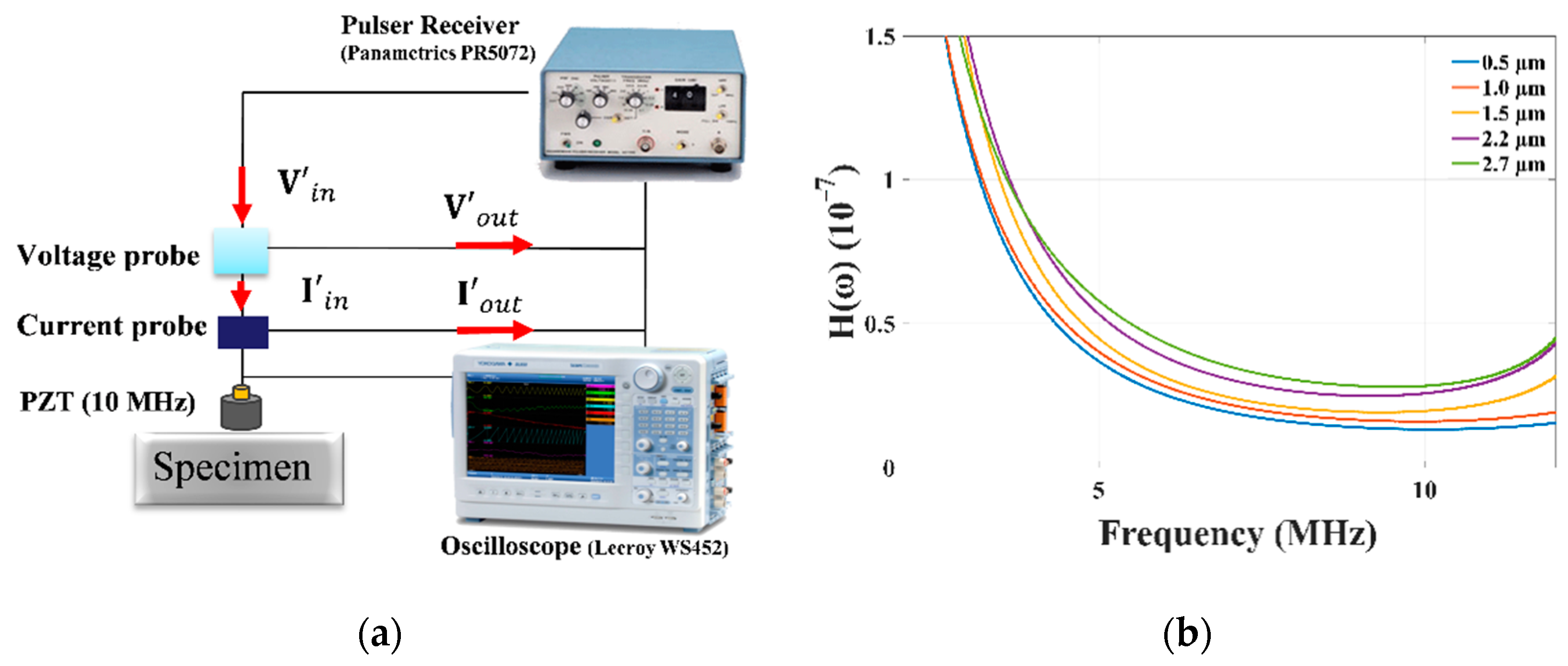
3.2. Absolute Nonlinearity Parameter Measurement

The piezoelectric method was carried out at room temperature to measure the absolute ultrasonic nonlinearity parameter [13], which involved two steps: calibration and nonlinear measurement. The calibration process converts a measured electrical current into acoustic displacement. Calibration was conducted using the pulse-echo method, as shown in Figure 2a, to obtain the calibration function that converts the electrical output signal of the receiving transducer into the displacement amplitude [12,13]. Calibration was carried out for the 0.25-in 10-MHz PZT transducer used as the receiver during the nonlinear measurements. A couplant was applied between the material and transducer. An ultrasonic pulser-receiver (Panamertrics, PR5072, New York, NY, USA) was used to transmit a broadband ultrasonic wave into the specimen. The incident ultrasonic wave propagated through the specimen. The propagating ultrasonic wave was reflected from the back wall and received by the 10-MHz PZT transducer. During calibration, the input current, I i n , and voltage, V i n , from the pulser to the transducer were detected, and the output current, I o u t , and voltage, V o u t , which were echo signals from the back wall, were measured using a current probe (Lecroy, CP030, Milpitas, NY, USA) and a voltage probe (Tektronix, P2220, Beaverton, OR, USA). The signal was acquired by an oscilloscope (Lecroy, Wavesurfer452, Chestnut Ridge, NY, USA). The acquired voltage and current signals were Fourier-transformed using fast Fourier transform (FFT) after applying a Hanning window. To compensate for the energy loss occurring because of windowing, the frequency spectrum is multiplied by a scaling factor [12,22]. From the final spectrum, we calculated the calibration function, H ( ω ) , as follows [13]:
H ( ω ) = | I i n ( ω ) ( V o u t ( ω ) I o u t ( ω ) ) + V i n ( ω ) | 2 ω 2 ρ υ a | I o u t ( ω ) | ,
where ω is the frequency of the propagating ultrasonic wave, ρ is the density of the material, υ is the longitudinal velocity of the propagating ultrasonic wave, and a is the area of the receiving transducer. Figure 2b shows the H ( ω ) values, which converts a measured electrical current into the acoustic displacement, obtained through calibration; H ( ω ) increases slightly as the surface roughness increases owing to scattering of the propagating ultrasonic wave. H ( ω ) values at interesting frequencies (5 and 10 MHz) are listed in Table 1.
After calibration, the nonlinear measurements were carried out using the through-transmission technique, as shown in Figure 3a. A 0.25-in 5-MHz PZT transducer was used as the transmitter and a 10-MHz PZT transducer was used as the receiver to sensitively receive the second-order harmonic frequency components. The nonlinear measurement process measures the second-order harmonic components in the electrical output signals after the ultrasonic wave passes through the material. A tone-burst signal with 20 cycles was generated using a high-power ultrasonic pulser (RITEC, RAM 5000, Warwick, RI, USA) to drive the transmitting transducer. This high-power signal passes through a 7-MHz low pass filter before driving the transmitting transducer to suppress the second-order frequency component generated within the pulser. During the nonlinear measurement, the contact pressure was maintained at 0.45 MPa using pneumatic equipment to maintain the contact condition of the receiving transducer with that existing during calibration [23]. The tone-burst current output, I o u t ( ω ) , was detected using the same current probe (Lecroy, CP030, NY, USA) that was used for calibration. The nonlinear measurements were repeated by increasing the input voltages. Figure 3b shows the tone-burst received current signals. The rectangular-marked tone-burst received current signal was processed via FFT excluding the transient and ringing parts to obtain I o u t ( ω ) . Figure 3c shows the FFT results of the received signals. As the roughness increased, the amplitude of the received signal in Figure 3b and the magnitude of the FFT result in Figure 3c decreased. Through calibration and nonlinear measurements, the displacement of the fundamental and second-order frequencies components after propagating through a material, A( ω ), was obtained using the calibration function, H ( ω ) , and current output spectrum, I o u t ( ω ) , as follows [13]:
A ( ω ) = | H ( ω ) | | I o u t ( ω ) |
The absolute nonlinearity parameter is generally measured using a contact transducer, namely a LiNbO3 or PZT transducer. The LiNbO3 transducer is a single-crystal material; thus, its nonlinearity is lower than that of the PZT transducer [24,25]. Therefore, the LiNbO3 transducer is widely used for measuring the absolute nonlinearity parameter to suppress the nonlinearity generated by the transducer [12]. However, the LiNbO3 transducer was not suitable for this experimental setup because it is fragile when used for measurements involving rough surfaces. Hence, we conducted experiments using the PZT transducer because the type of transducer does not affect the experiments performed to analyze the influence of the surface roughness on the parameter measurements.

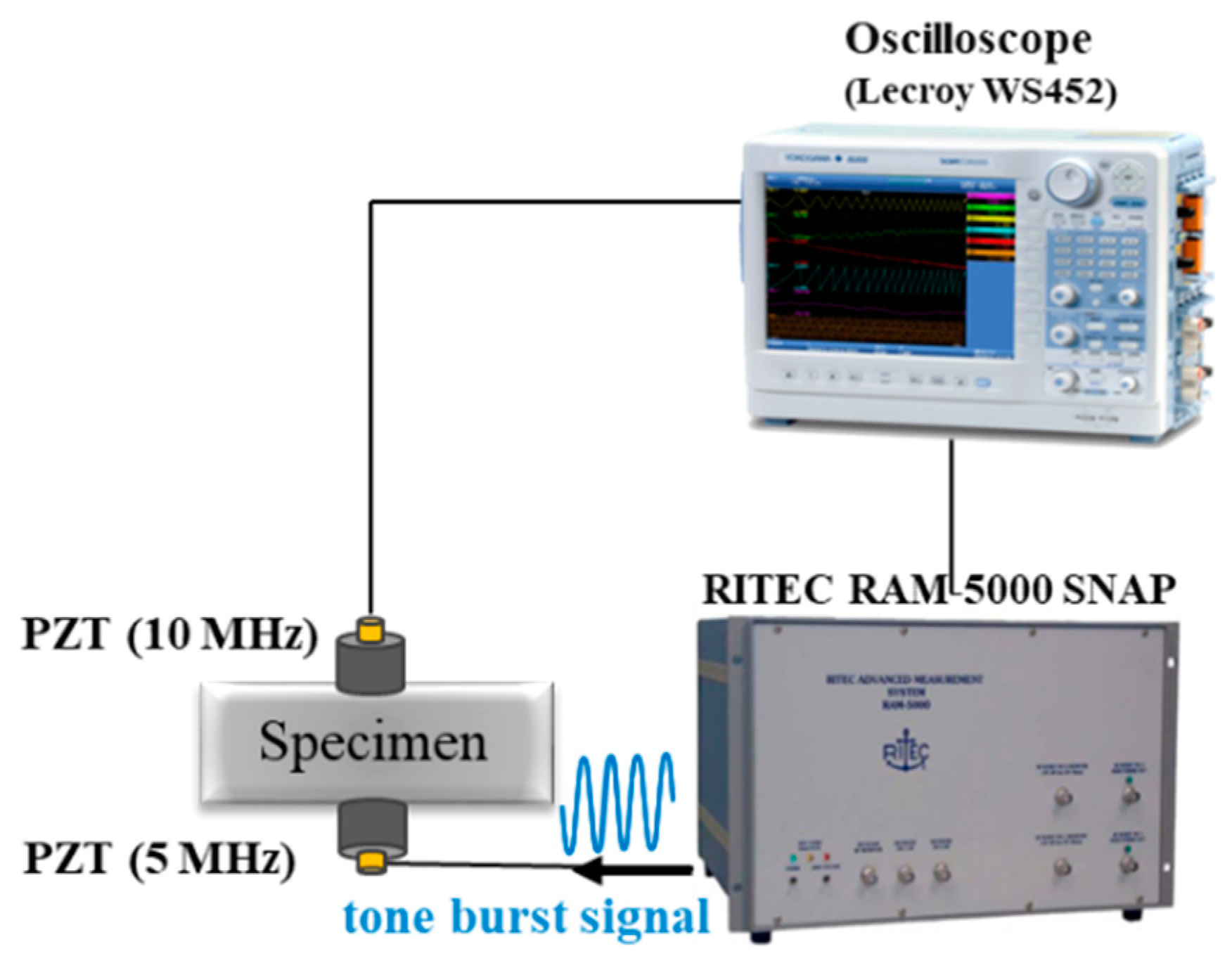
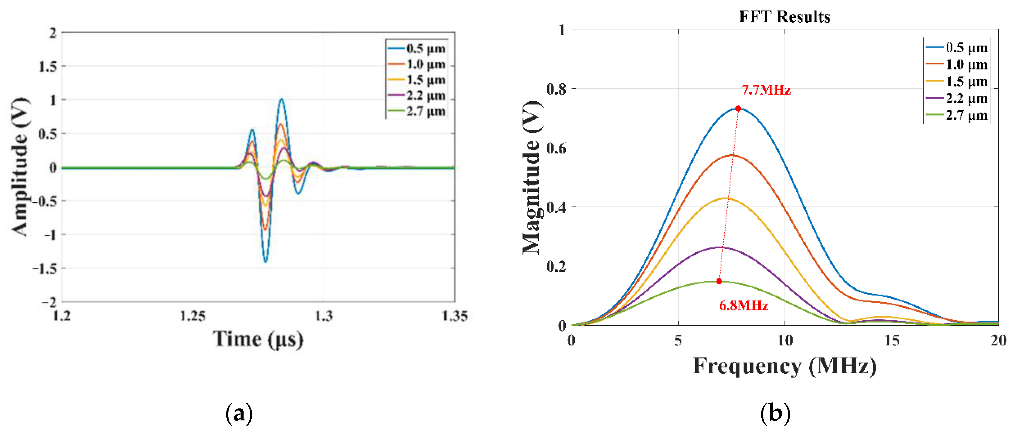
3.3. Relative Nonlinearity Parameter Measurement

After the absolute nonlinearity parameter measurement was completed, the relative nonlinearity parameter measurement was conducted, as shown in Figure 4. The experimental setup was the same as that used in the absolute nonlinear measurements. The only difference was that the relative nonlinear measurements detected the transducer output voltage signals directly. In the experiment, the electrical impedance was kept constant at 50 Ω [12], such that the measured tone-burst voltage signal was the same as the tone-burst current signal obtained in the absolute measurement but only in magnitude.

4. Experimental Results

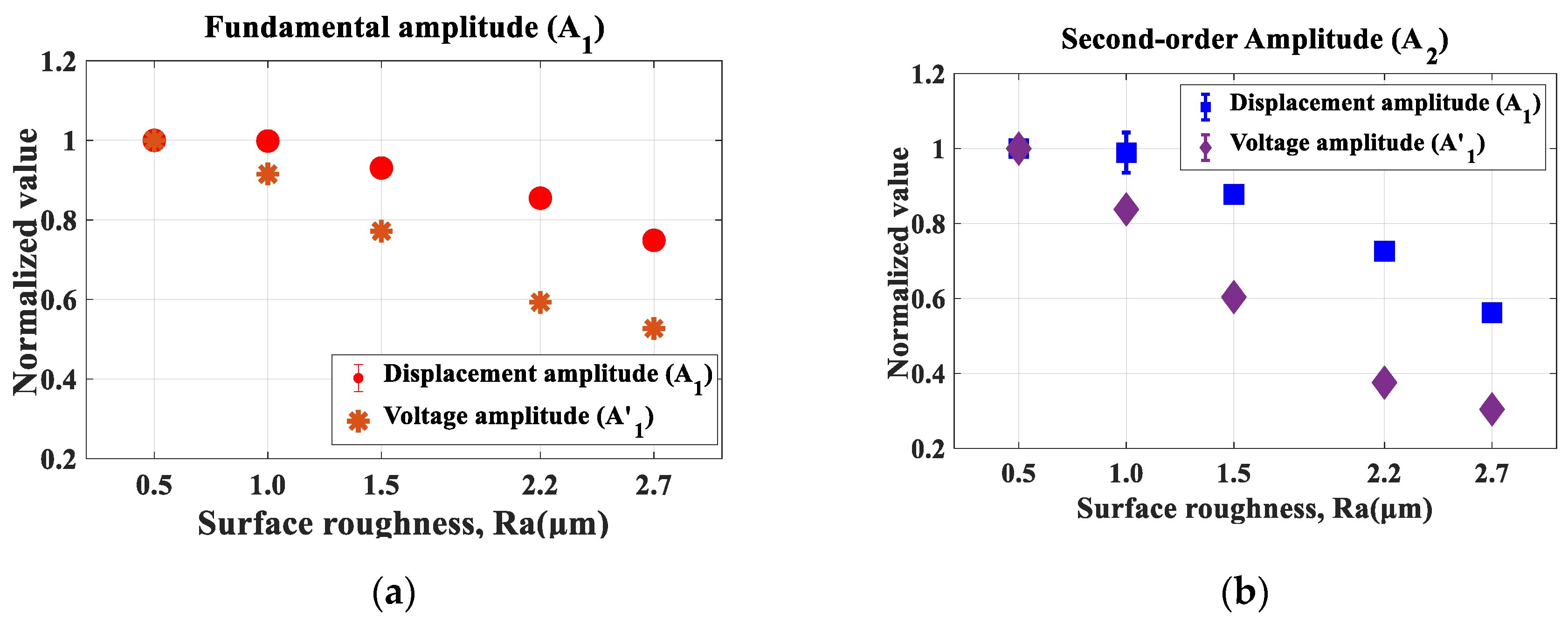
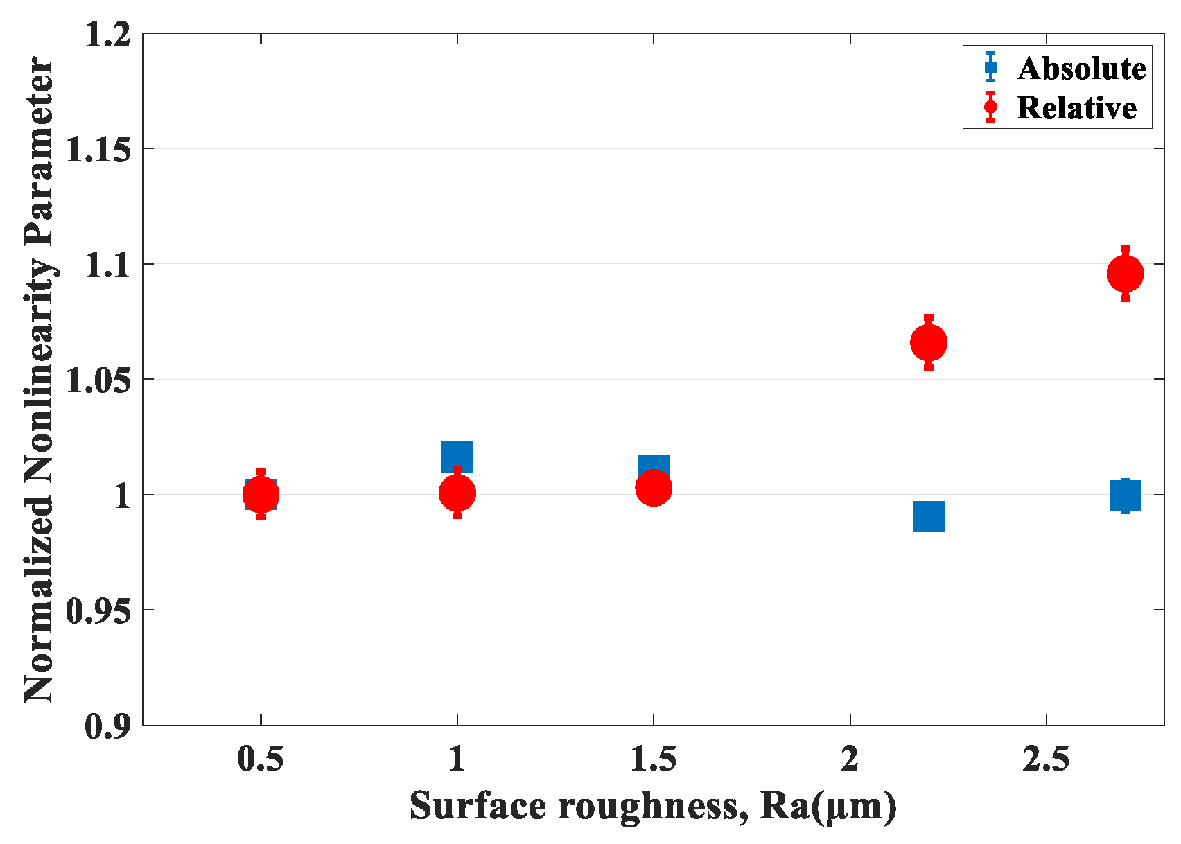
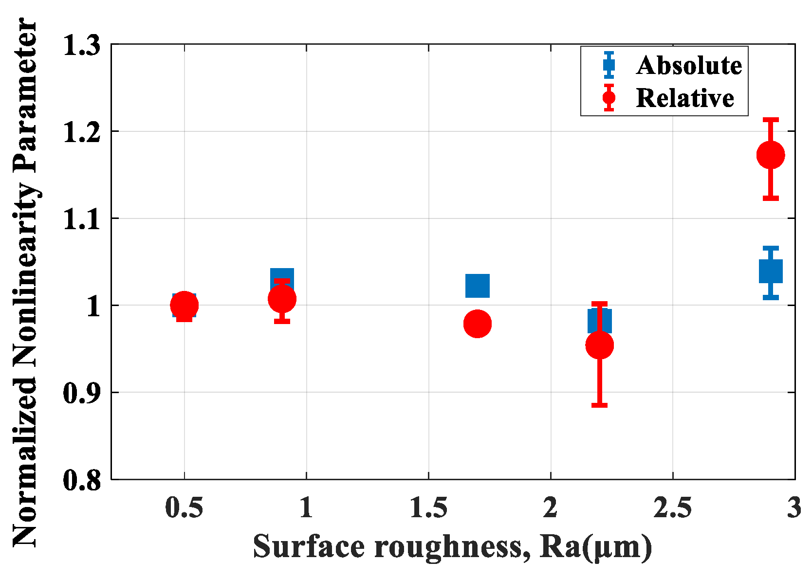
4.1. Rough Surfaces on both Sides

Figure 5 and Figure 6 show the absolute and relative nonlinear measurement results for Al 6061-T6 with rough transmission and reception surfaces (Ra = 0.5, 1.0, 1.5, 2.2, and 2.7 μm). The marked points represent the average of the measured data, and the error bar represents the range of the max and min values (repeatability error is small within 1%; thus, most error bars overlap with the marked points). Figure 5a shows the variation in the displacement amplitude, A 1 , obtained from the absolute measurements and the voltage amplitude, A 1 , obtained from the relative measurement of the fundamental frequency component with respect to the surface roughness by normalizing each initial value.
The voltage amplitude, A 1 , decreased sharply as the surface roughness increased; it decreased to 0.53 on the roughest surface (Ra = 2.7 μm). However, in the absolute measurements, the displacement amplitude, A 1 , remained unchanged up to Ra = 1.0 μm, and then decreased gradually as the surface roughness increased; it decreased to 0.75 on the roughest surface (Ra = 2.7 μm). Figure 5b shows the variation in A 2 and the voltage amplitude, A 2 , of the second-order harmonic component with respect to the surface roughness by normalizing each initial value. In the relative measurements, the voltage amplitude A 2 of the second-order harmonic component decreased sharply as the surface roughness increased; it decreased to 0.30 on the roughest surface (Ra = 2.7 μm). In contrast, in the absolute measurements, the displacement amplitude A 2 was constant up to Ra = 1.0 and then decreased gradually as the surface roughness increased; it decreased to 0.57 on the roughest surface (Ra = 2.7 μm). These experimental results show that voltage amplitudes A 1 and A 2 obtained from the relative measurements exhibit a steeper decrease than displacement amplitudes A 1 and A 2 obtained from the absolute measurements because the calibration function, H ( ω ) , obtained through calibration increases slightly as the surface roughness increases (Figure 2b). In other words, the variations in the sensitivity of the receiving transducer caused by the surface roughness are compensated by H ( ω ) .
Figure 6 shows the normalized absolute and relative nonlinearity parameters for Al 6061-T6 with respect to their surface roughness. The absolute nonlinearity parameter barely changes with the increasing surface roughness. In contrast, the relative nonlinearity parameter barely changes up to Ra = 1.5 μm, as observed for the absolute nonlinearity parameter, and then increased sharply as the surface roughness increased; it increased to 1.15 on the roughest surface (Ra = 2.7 μm). These results show that the absolute nonlinearity parameter changes by a smaller degree than the relative nonlinearity parameter according to variations in the surface roughness. The absolute nonlinearity parameter can compensate for the influence of the surface roughness using the calibration function obtained from the calibration process in the absolute measurements; thus, the influence of surface roughness is different from that observed for the relative nonlinearity parameter.
Figure 7 shows the normalized absolute and relative nonlinearity parameters for SUS 304 specimens with respect to the surface roughness (Ra = 0.5, 0.9, 1.7, 2.2, and 2.9 μm). The absolute nonlinearity parameter barely changes with the increasing surface roughness. The relative nonlinearity parameter barely changes up to Ra = 2.2 μm, as observed for the absolute nonlinearity parameter. It then increased sharply as the surface roughness increased; it increased to 1.17 on the roughest surface (Ra = 2.9 μm). Consequently, the absolute nonlinearity parameter changed by a smaller degree than the relative nonlinearity parameter according to the variations in the surface roughness. This result is similar to that obtained for Al 6161-T6 (Figure 6). Although there is a small difference in the Ra at which the relative nonlinearity parameter changes (Al 6061-T6: Ra > 1.5 μm; SUS 304: Ra > 2.2 μm), comparisons of the measurement results for Al 6161-T6 and SUS 304 specimens indicate that the results are similar overall. Therefore, we believe that the variation in the nonlinearity parameter with surface roughness is less related to the material properties.
These tendencies shown in Figure 5, Figure 6 and Figure 7 can be explained using Figure 8, which shows the pulse-echo measurement results for Al 6061-T6 with a 10-MHz transducer used as the receiving transducer. Figure 8a shows the received signal obtained using the pulse-echo method with respect to the surface roughness. The amplitude of the received signal decreases with variations in the surface roughness, indicating that the signal reception sensitivity decreases. Figure 8b shows the spectrum obtained from the FFT results of the received signal. The resonance frequency was 7.7 MHz for the reference specimen (Ra = 0.5 μm) and 6.8 MHz for a rough surface (Ra = 2.7 μm) because the attenuation and scattering of the received signal caused by the surface roughness are more severe at a higher frequency than at a lower frequency. As the resonant frequency of the receiving transducer decreased, the relative sensitivity of the transducer changed at 5 and 10 MHz, i.e., the frequencies of interest [19]. Additionally, the received voltage amplitudes, A 1 and A 2 , obtained from the relative nonlinear measurements decrease as shown in Figure 5, thus causing a change in the relative nonlinearity parameter as shown in Figure 6 and Figure 7. However, because the relative nonlinearity parameter is inversely proportional to the square of the voltage amplitude of the fundamental wave component ( A 1 2 ) and proportional to the voltage amplitude of the second-order harmonic component ( A 2 ), the shifting of the resonant frequency of the receiving transducer to a lower value does not indicate a decrease in the relative nonlinearity parameter.

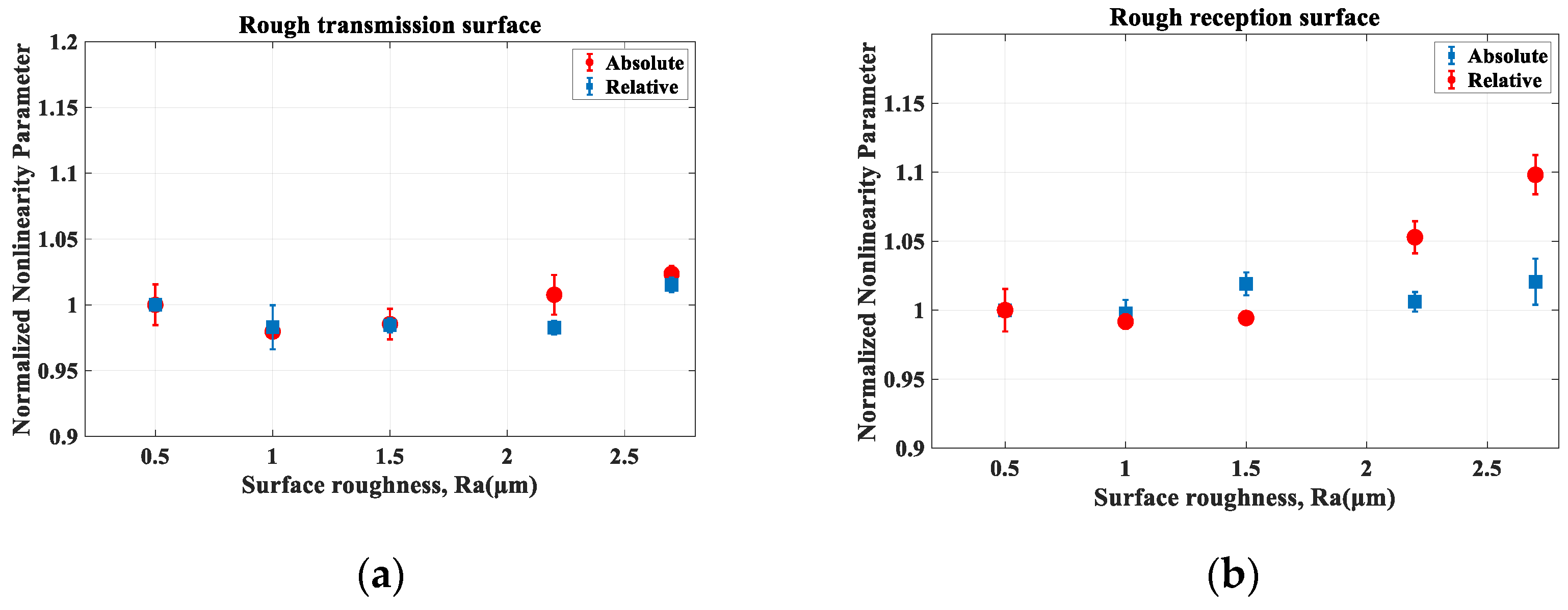
4.2. Al 6061-T6 with One Rough Surface and One Smooth Surface

Next, we examined the case where either the transmission or reception surface was rough for Al 6061-T6 specimens, as shown in Figure 1b. Figure 9a shows the absolute and relative nonlinearity parameters for a specimen with a rough transmission surface (Ra = 0.5, 1.0, 1.5, 2.2, and 2.7 μm) and smooth reception surface (Ra = 0.5 μm). The absolute and relative nonlinearity parameters exhibit no noticeable changes with the increase in the surface roughness. Figure 9b shows the absolute and relative nonlinearity parameter results for specimens with a rough reception surface (Ra = 0.5, 1.0, 1.5, 2.2, and 2.7 μm) and smooth transmission surface (Ra = 0.5 μm). In other words, the positions of the transmitting and receiving transducers are reversed. The absolute nonlinearity parameter does not change noticeably as the surface roughness increases, whereas the relative nonlinearity parameter increases as the surface roughness increases beyond a certain level (Ra > 1.5 μm). These variations in the nonlinearity parameter are because of the increased attenuation and scattering at higher frequencies and the difference in the receiving sensitivity caused by the frequency, as described above. These experimental results indicate that the roughness of the reception surface has more influence on the nonlinearity parameter measurements. We inferred that the amplitude of the ultrasonic wave, which is smaller in the receiving part than in the transmitting part, was significantly influenced by the surface roughness.

5. Conclusions

This study analyzed the influence of the surface roughness on ultrasonic nonlinearity parameter measurements. For this purpose, Al6061-T6 and SUS304 specimens with different surface roughness on both sides were prepared (ranging from 0.5 to 3 μm); additionally, Al6061-T6 specimens with one rough surface and one smooth surface were prepared. Then, the absolute and relative ultrasonic nonlinearity measurement experiments were conducted using the through-transmission technique.
When both surfaces of the specimen were rough, the absolute nonlinearity parameter showed no noticeable change as the surface roughness increased when compared to the relative nonlinearity parameter. This was because the influence of the surface roughness was compensated by the calibration function obtained from calibration during absolute nonlinear measurements. These results were similar for the Al6061-T6 and SUS304 specimens. Therefore, the variation in the nonlinearity parameter with roughness is less related to the material properties. Furthermore, a rough reception surface affected the relative nonlinearity parameter more than a rough transmission surface.
Therefore, it is desirable to measure the nonlinearity parameter after polishing the material surface to reduce the roughness to approximately Ra < 1.5 μm to ensure the reliability of the nonlinearity parameter measurements using a contact transducer. For rough surfaces, the absolute nonlinearity parameter measurement is more accurate than the relative nonlinearity parameter measurement. These results can be used to improve the reliability of ultrasonic nonlinearity parameter measurements on rough surfaces formed because of oxidation and corrosion.

Author Contributions

Conceptualization, J.K., H.-P.H., and K.-Y.J.; methodology, J.K., and H.-P.H.; software, J.K., and H.-P.H.; validation, J.K., H.-P.H., and K.-Y.J. formal analysis, J.K., and H.-P.H.; investigation, J.K., and H.-P.H.; resources, J.K., and H.-P.H.; data curation, J.K., and H.-P.H.; writing—original draft preparation, J.K.; writing—review and editing, J.K., K.-M.K., and K.-Y.J.; visualization, J.K., and H.-P.H.; supervision, K.-Y.J.; project administration, K.-M.K., and K.-Y.J.; funding acquisition, K.-M.K., and K.-Y.J. All authors have read and agreed to the published version of the manuscript.

Funding

This research was supported by the Nuclear Power Research and Development Program through the National Research Foundation of Korea (NRF) funded by the Ministry of Science, ICT & Future Planning (NRF-2013M2A2A9043241), and the Ministry of Education (NRF-2017R1D1A1B03027828).

Conflicts of Interest

The authors declare no conflict of interest.

References

  1. Jhang, K.-Y. Nonlinear ultrasonic techniques for nondestructive assessment of micro damage in material: A review. Int. J. Precis. Eng. Manuf. 2009, 10, 123–135. [Google Scholar] [CrossRef]
  2. Jhang, K.-Y. Application of nonlinear ultrasonics to the NDE of material degradation. IEEE Trans. Ultrason. Ferroelectr. Freq. Control 2000, 47, 540–548. [Google Scholar] [CrossRef]
  3. Cantrell, J.H.; Yost, W.T. Effect of precipitate coherency strains on acoustic harmonic generation. J. Appl. Phys. 1997, 81, 2957–2962. [Google Scholar] [CrossRef]
  4. Hikata, A.; Chick, B.B.; Elbaum, C. Dislocation contribution to the second harmonic generation of ultrasonic waves. J. Appl. Phys. 1965, 36, 229–236. [Google Scholar] [CrossRef]
  5. Kim, J.-Y.; Jacobs, L.J.; Qu, J.; Littles, J.W. Experimental characterization of fatigue damage in a nickel-base superalloy using nonlinear ultrasonic waves. J. Acoust. Soc. Am. 2006, 120, 1266–1273. [Google Scholar] [CrossRef]
  6. Cantrell, J.H. Quantitative assessment of fatigue damage accumulation in wavy slip metals from acoustic harmonic generation. Philos. Mag. 2006, 86, 1539–1554. [Google Scholar] [CrossRef] [Green Version]
  7. Hong, M.; Su, Z.; Wang, Q.; Cheng, L.; Qing, X. Modeling nonlinearities of ultrasonic waves for fatigue damage characterization: Theory, simulation, and experimental validation. Ultrasonics 2014, 54, 770–778. [Google Scholar] [CrossRef]
  8. Balasubramaniam, K.; Valluri, J.S.; Prakash, R.V. Creep damage characterization using a low amplitude nonlinear ultrasonic technique. Mater. Charact. 2011, 62, 275–286. [Google Scholar] [CrossRef]
  9. Kim, J.; Jhang, K.-Y. Evaluation of ultrasonic nonlinear characteristics in heat-treated aluminum alloy (Al-Mg-Si-Cu). Adv. Mater. Sci. Eng. 2013, 407846, 1–6. [Google Scholar] [CrossRef] [Green Version]
  10. Kim, J.; Jhang, K.-Y. Assessment of thermal degradation by cumulative variation of ultrasonic nonlinear parameter. Int. J. Precis. Eng. Manuf. 2017, 18, 23–29. [Google Scholar] [CrossRef]
  11. Xiang, Y.; Deng, M.; Xuan, F.-Z. Thermal degradation evaluation of HP40Nb alloy steel after long term service using a nonlinear ultrasonic technique. J. Nondestruct. Eval. 2014, 33, 279–287. [Google Scholar] [CrossRef]
  12. Kim, J.; Song, D.-G.; Jhang, K.-Y. Absolute measurement and relative measurement of ultrasonic nonlinear parameters. Res. Nondestruct. Eval. 2017, 28, 211–225. [Google Scholar] [CrossRef] [Green Version]
  13. Dace, G.E.; Thompson, R.B.; Buck, O. Measurement of the acoustic harmonic generation for materials characterization using contact transducers. Rev. Prog. Quant. Nondestruct. Eval. 1992, 11B, 2069–2076. [Google Scholar]
  14. Yost, W.T.; Cantrell, J.H. Absolute ultrasonic displacement amplitude measurements with a submersible electrostatic acoustic transducer. Rev. Sci. Instrum. 1992, 63, 4182–4188. [Google Scholar] [CrossRef]
  15. Hurley, D.C.; Fortunko, C.M. Determination of the nonlinear ultrasonic parameter using a Michelson interferometer. Meas. Sci. Technol. 1997, 8, 634–642. [Google Scholar] [CrossRef]
  16. Bilgen, M.; Rose, J.H. Rough-surface effects on incoherent scattering from random volumetric scatterers: Approximate analytic series solution. J. Acoust. Soc. Am. 1994, 96, 2856–2869. [Google Scholar] [CrossRef]
  17. Wilhjelm, J.E.; Pedersen, P.C.; Jacobsen, S.M. The influence of roughness, angle, range, and transducer type on the echo signal from planar interfaces. IEEE Trans. Ultrason. Ferroelectr. Freq. Control 2001, 48, 511–521. [Google Scholar] [CrossRef] [Green Version]
  18. Nagy, P.B.; Adler, L. Surface roughness induced attenuation of reflected and transmitted ultrasonic waves. J. Acoust. Soc. Am. 1987, 82, 193–197. [Google Scholar] [CrossRef]
  19. Sukmana, D.D.; Ihara, I. Application of air-coupled ultrasound to noncontact surface roughness evaluation. Jpn. J. Appl. Phys. 2005, 44, 4417–4420. [Google Scholar] [CrossRef]
  20. Na, J.K. Effects of surface roughness and nonparallelism on the measurement of the acoustic nonlinearity parameter in steam turbine blades. AIP Conf. Proceed. 2000, 509, 1417–1424. [Google Scholar]
  21. Chakrapani, S.K.; Howard, A.; Barnard, D. Influence of surface roughness on the measurement of acoustic nonlinearity parameter of solids using contact piezoelectric transducers. Ultrasonics 2018, 84, 112–118. [Google Scholar] [CrossRef]
  22. Lee, K.-J.; Kim, J.; Song, D.-G.; Jhang, K.-Y. Effect of window function for measurement of ultrasonic nonlinear parameter using fast fourier transform of tone-burst signal. J. Korean Soc. Nondestruct. Test. 2015, 35, 251–257. [Google Scholar] [CrossRef] [Green Version]
  23. Choi, I.-H.; Lee, J.-I.; Kwon, G.-D.; Jhang, K.-Y. Effect of system dependent harmonics in the measurement of ultrasonic nonlinear parameter by using contact transducers. J. Korean Soc. Nondestruct. Test. 2008, 28, 358–363. [Google Scholar]
  24. Zheng, Y.; Maev, R.G.; Solodov, I.Y. Review/Sythèse nonlinear acoustic applications for material characterization: A review. Can. J. Phys. 2000, 77, 927–967. [Google Scholar] [CrossRef]
  25. Kim, J.; Lee, K.-J.; Jhang, K.-Y. Comparison of ultrasonic nonlinear parameters measured by PZT and LiNbO3 transducers. In Proceedings of the 42nd Annual Review of Progress in Quantitative Nondestructive Evaluation, Minneapolis, MN, USA, 26–31 July 2016; Volume 1706, p. 060008. [Google Scholar]
Figure 1. Experimental procedures for (a) both rough surfaces; (b) one rough surface and one smooth surface.
Applsci 10 08661 g001
Figure 2. (a) Experimental setup and (b) calibration curve.
Applsci 10 08661 g002
Figure 3. (a) Experimental setup; (b) received tone-burst current signals; (c) spectrum of the received current signal for absolute nonlinear measurement.
Applsci 10 08661 g003
Figure 4. Experimental setup for absolute measurements.
Applsci 10 08661 g004
Figure 5. Variations in (a) fundamental frequency component ( A 1 and A 1 ); (b) second-order frequency component ( A 2 and A 2 ) in absolute and relative measurements for Al 6061-T6 with respect to the surface roughness.
Applsci 10 08661 g005
Figure 6. Variations in the absolute and relative nonlinearity parameters for Al 6061-T6 with respect to the surface roughness.
Applsci 10 08661 g006
Figure 7. Variations in the absolute and relative nonlinearity parameters for SUS 304 with respect to the surface roughness.
Applsci 10 08661 g007
Figure 8. (a) Received pulse-echo signals and (b) spectrum of the received signal.
Applsci 10 08661 g008
Figure 9. Experimental results of the absolute and relative ultrasonic nonlinearity measurements on (a) rough transmission surface and (b) rough reception surface.
Applsci 10 08661 g009
Table 1. H(ω) value according to the surface roughness.
H ( ω ) 0.5 μm1.0 μm1.5 μm2.2 μm2.7 μm
5 MHz3.69 × 10−84.03 × 10−84.49 × 10−85.26 × 10−85.34 × 10−8
10 MHz1.33 × 10−81.61 × 10−81.97 × 10−82.49 × 10−82.84 × 10−8
Publisher’s Note: MDPI stays neutral with regard to jurisdictional claims in published maps and institutional affiliations.

