Article

A Haptic Feedback Actuator Suitable for the Soft Wearable Device

1
Qian Xuesen Laboratory of Space Technology, China Academy of Space Technology, No. 104 Youyi Rd., Haidian District, Beijing 100094, China
2
College of Mechanical and Electrical Engineering, Beijing University of Chemical Technology, North Third Ring Road 15, Chaoyang District, Beijing 100029, China
*
Authors to whom correspondence should be addressed.
The authors contributed equally to this work.
Appl. Sci. 2020, 10(24), 8827; https://doi.org/10.3390/app10248827 (registering DOI)
Submission received: 8 November 2020 / Revised: 25 November 2020 / Accepted: 4 December 2020 / Published: 10 December 2020
(This article belongs to the Special Issue Smart Materials and Structures)

Abstract

:
Gaining direct tactile sensation is becoming increasingly important for humans in human–computer interaction fields such as space robot teleoperation and augmented reality (AR). In this study, a novel electro-hydraulic soft actuator was designed and manufactured. The proposed actuator is composed of polydimethylsiloxane (PDMS) films, flexible electrodes, and an insulating liquid dielectric. The influence of two different voltage loading methods on the output characteristics of the actuator was studied. The special voltage loading method (AC voltage) enables the actuator to respond rapidly (within 0.15 s), output a stable displacement in 3 s, and remain unchanged in the subsequent time. By adjusting the voltages and frequencies, a maximum output displacement of 1.1 mm and an output force of 1 N/cm2 can be rapidly achieved at a voltage of 12 kV (20 Hz). Finally, a haptic feedback system was built to control the robotic hand to perform gripping tasks in real time, and a more realistic tactile sensation could be realized, similar to that obtained when a human directly grabs objects. Therefore, the actuator has excellent portability, robustness, rapid response, and good compatibility with the human body for human–computer interaction.

1. Introduction

As an important way for humans to perceive the outside world, tactile sensation is essential to perform many precision operations in daily life, and it is also increasingly applied in human–computer interaction devices [1] to enhance the sense of reality and immersion. For many teleoperation tasks, people often need to control a machine to perform precise operations, in which perfect coordination of visual, auditory, and especially tactile feelings is required. To improve significantly the effectiveness of remote operations and the safety of operators, a haptic feedback device capable of reproducing tactile sensations in real time while the controlled robotic hand touches a remote object is urgently needed.
Traditional haptic feedback devices are mainly composed of rigid structures [2,3], which provide force feedback to the operators through a steering gear [4,5]. These devices are usually bulky, not portable, and have poor compatibility with the human body. To overcome these shortcomings, an increasing number of haptic feedback actuators made of soft materials [6,7,8] have been created in recent years. They are small in size, friendly with humans, and provide convenient conditions for the emergence of wearable haptic feedback devices [9,10,11,12,13,14,15]. To create a good tactile sensation, the soft actuator should respond rapidly, output a large displacement and force, and be safe and flexible to be integrated with a glove.
Song et al. [16] designed an electro-pneumatic haptic feedback actuator placed at the end of a human finger for virtual reality (VR) systems. The gas in the actuator was squeezed by the Maxwell force between two electrodes, and correspondingly, a displacement was produced. However, the actuator only provided a maximum displacement of 0.125 mm. Sichao Hou et al. [17] proposed a photothermally driven refreshable micro-actuator based on graphene-oxide-doped paraffin. The output of the actuator was achieved by the volume change during the phase change of the material. The actuator output a displacement of 1.76 mm in a circular area with final diameter of 10 mm, but the process required approximately 150 s. Hyuk-Jun Kwon et al. [18] created a thermo-pneumatic actuator applied to a braille dot display module. The working fluid in the actuator was heated to vaporize, and the pressure in the sealed cavity was increased to achieve actuation. The actuator produced a maximum deflection of 1.37 mm at 100 s. Although very little power was required, the response time was still very long. Hyung Seok Lee et al. [19] proposed a liquid-coupled actuator based on a dielectric elastomer. The actuation was realized by applying voltages to one side of the dielectric elastomer, which produced the maximum displacement change (0.35 mm) on the other side. Chakrabortia et al. [20] provided an electroactive polymer actuator made of commercially available silicone tubing. The silicone tube became mechanically anisotropic by applying asymmetric pretension in the circumferential and axial directions, which caused the actuator to generate an axial strain under an electric field. However, it is difficult to avoid the use of rigid frames for the dielectric elastomer, which undergoes little deformation, thus limiting the application of the soft actuator.
In this paper, an electro-hydraulic actuator is proposed for haptic feedback. Compared with other dielectric elastomer (DE) actuators [21,22], this actuator is entirely soft without rigid frames. In addition, the actuator has a hydraulically amplified self-healing ability [23,24,25], and thus, it is more suitable to resist a high voltage. The actuator is very flexible and safe, and it is a good fit for wearable devices owing to its well-designed structure and advanced preparation technology.

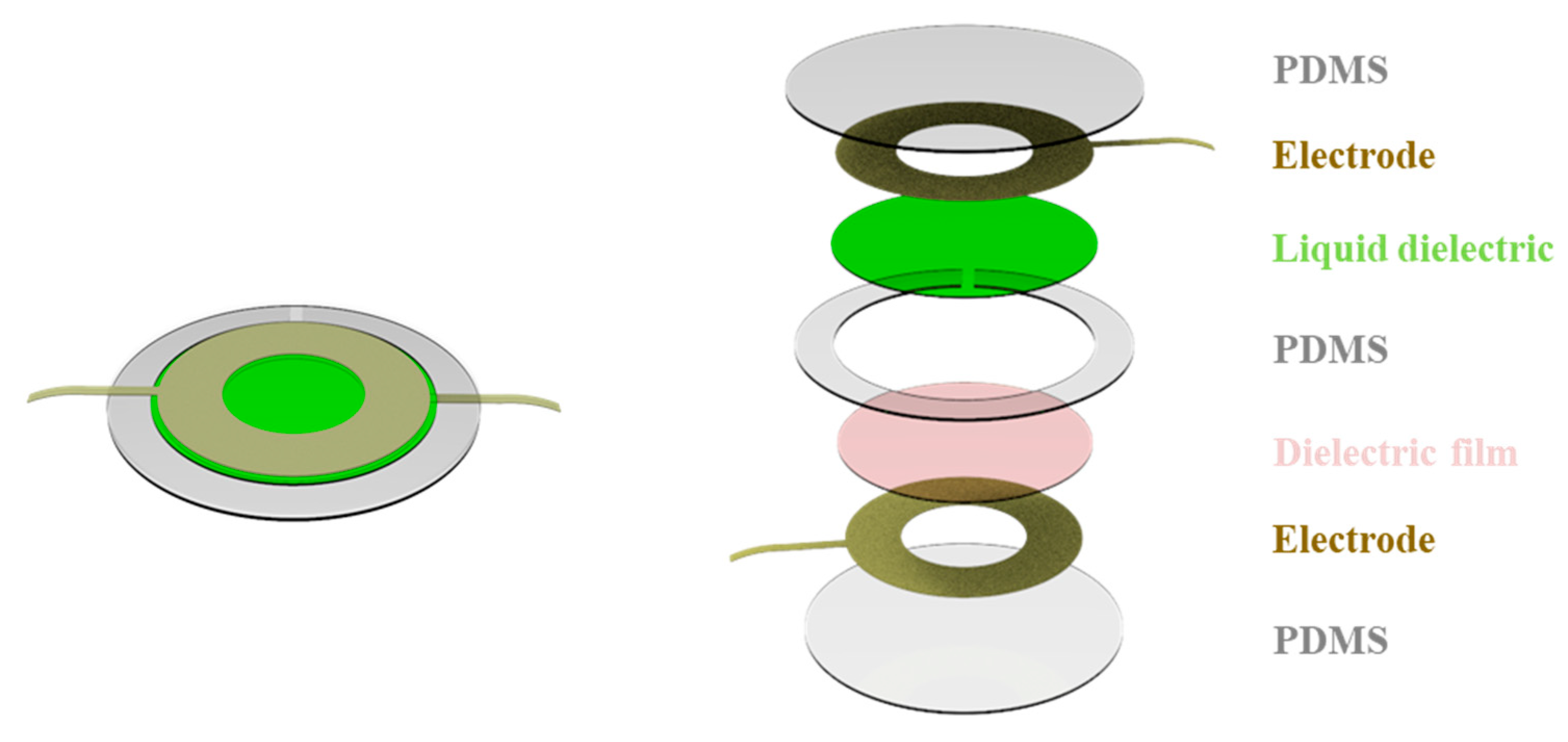
2. Design of Electro-Hydraulic Haptic Feedback Actuator

As shown in Figure 1, the parts of the electro-hydraulic haptic feedback actuator, from top to bottom, are circular polydimethylsiloxane (PDMS) films, annular electrodes, insulating liquid dielectrics, annular PDMS films, circular dielectric films, annular electrodes, and circular PDMS films. Three layers of PDMS films form a piece of flat, thin, and hollow tablet filled with a type of insulating liquid dielectric. Inside the tablet, a pair of flexible but not stretchable annular electrodes are glued with the upper and lower PDMS films, respectively. Therefore, the two electrodes inside the actuator are insulated from each other by the liquid dielectric and the dielectric film.
Figure 2a–d show the action principle of the actuator. When the voltage is applied, the Maxwell force occurs between the two annular electrodes. Then, the internal insulating liquid dielectric in the annular area is squeezed into the center area. The underlying dielectric film restricts the downward flow of the insulating liquid dielectric, and the center part of the upper PDMS film bulges. The annular electrodes provide space for the internal insulating liquid dielectric to flow, and it realizes displacement and force output as a tactile feedback area. The in-situ structure of the electro-hydraulic actuator eliminates the long flow channels of traditional fluid actuators, and the resistance loss is reduced during the actuation process. In addition, the insulating liquid in the cavity can serve not only as a medium for pressure transmission but also as an insulating medium to isolate the two annular electrodes. Therefore, the liquid dielectric can increase the breakdown voltage threshold of the actuator.
To analyze the relationship between the Maxwell force and the output of the actuator qualitatively, some parameters were derived as follows. When the two electrodes are energized, the Maxwell electric field force between them can be expressed by the following formula:
F e = 1 2 ε A ( V h ) 2
where ε is the absolute permittivity of the actuator, A is the area of the annular electrode, V is the applied voltage, and h is the thickness of the inner chamber.
Considering the incompressibility of the liquid dielectric, the volume of the actuator should be invariable before and after applying a voltage. The thickness variation can be approximately calculated as
Δ h = π · H 3 6 D 0 + π · D 2 · H 8 D 0
where H is the arched height, D is the inner diameter of the annular electrode, and D0 is the diameter of the inner chamber, as shown in Figure 2.
The driving characteristics of the actuator are affected by the Maxwell force. Equation (1) indicates that the Maxwell force is related to the voltage applied on the two electrodes, distance, and relative area between the electrodes. To increase the Maxwell force, the two electrodes are placed inside the dielectric films to reduce the distance between them, as shown in Figure 1. In addition, the relative area between the electrodes should be enlarged as much as possible. However, this area contradicts a compact design. After several tests, the key structural parameters of the actuator were determined to gain a good haptic feedback effect, and the parameters are described in the Experimental section.

3. Materials and Methods

3.1. Fabrication

As shown in Figure 3, the PDMS and the cross-linker (Sylgard 184, Dow-Corning, Midland, MI, USA) were mixed at a ratio of 10:1. Then, the mixture was poured into a 3D-printed rectangular trough with a depth of 0.3 mm. It was placed in a vacuum desiccator for 10 min to discharge the gas. After heating at 70 °C for 30 min, the mixture was removed to obtain a PDMS film with a thickness of 0.3 mm. A laser cutting machine (VLS 3.50, Universal, USA) was used to cut the film to obtain two circular sheets with a diameter of 40 mm and one annular sheet with an outer diameter of 40 mm and an inner diameter of 23 mm. The electrode material(Conductive tape, Crystal silicon electronic thchnology, Suzhou, China), which is a commercial conductive tape, was also cut to obtain two uniform rings with an outer diameter of 20 mm and an inner diameter of 10 mm. PDMS was used to bond three layers of the PDMS films. The two electrodes were glued to the internal surfaces of the PDMS films, and a dielectric biaxially oriented polypropylene (BOPP) film(BOPP Film, Kaida new packaging materials, Bazhou, China) was placed into the cavity to isolate the two electrodes. Finally, a syringe was used to replace the air of the cavity with the insulating oil (Envirotemp FR3, Cargill, Minnesota, US), and then Ecoflex-0030 ((Ecoflex-0030, Smooth-On, Pennsylvania, USA)) was used to seal the injection inlet to obtain the final actuator.

3.2. Test Methods

3.2.1. Output Displacement Measurement

The actuator was placed horizontally on the measuring platform. A black label was placed in the center area of the actuator for accurate measurement. The position of the laser displacement sensor (HG-C1050, Panasonic, Osaka, Japan) was adjusted to align with the label. The displacement changes of the actuator were collected by the laser displacement sensor in real time and stored in a computer (the acquisition rate was 100,000 times/s).

3.2.2. Output Force Measurement

The actuator was placed horizontally on the measuring platform. Different weights were placed on the actuator. The contact area of the actuator was 7 mm2. At the top of the weights, a laser sensor was used to measure the displacement of the device. The data were read in real time. The change in displacement of the device was collected by the laser sensor and stored in the computer (the acquisition rate was 100,000 times/s).

4. Results and Discussion

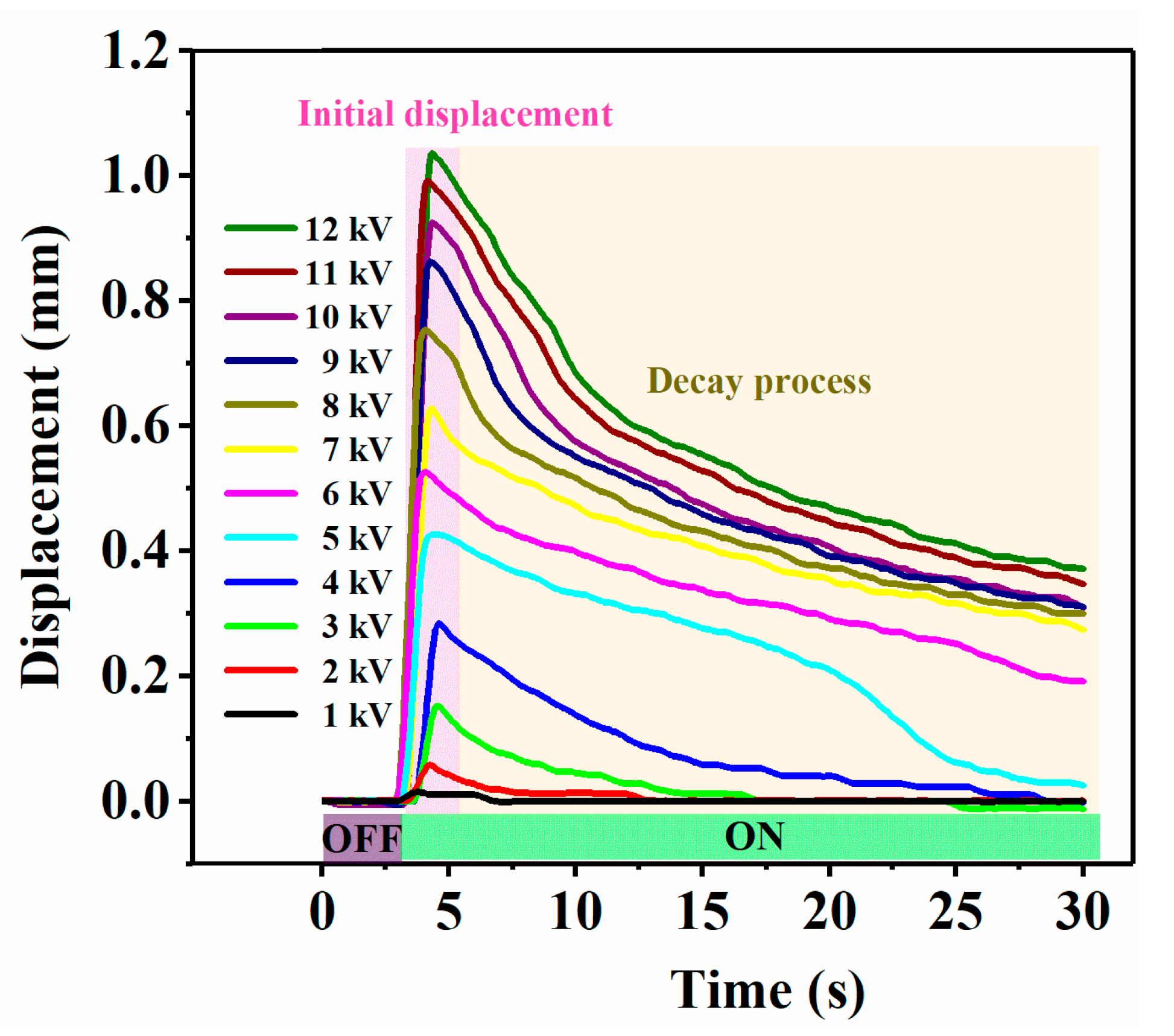
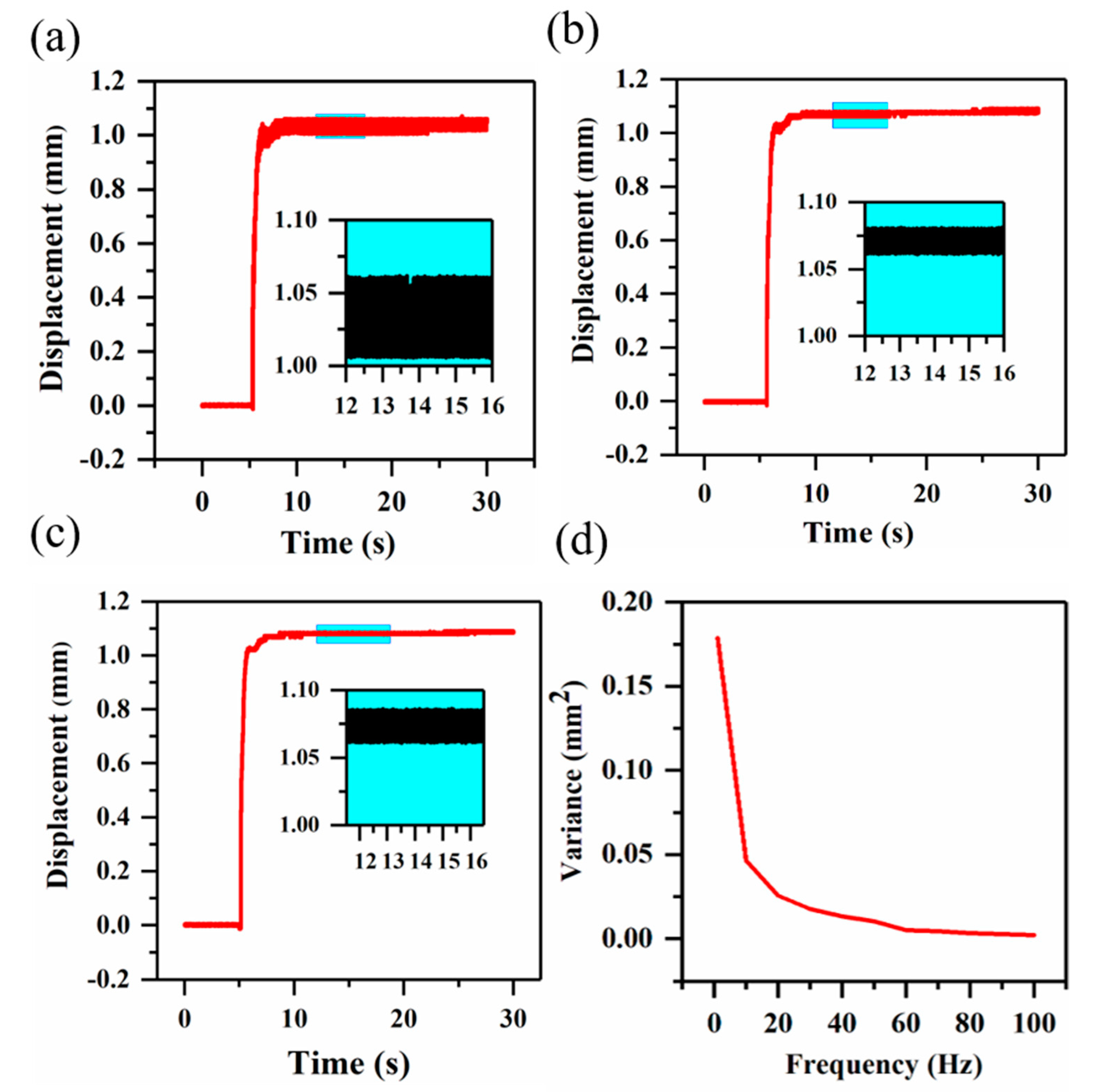
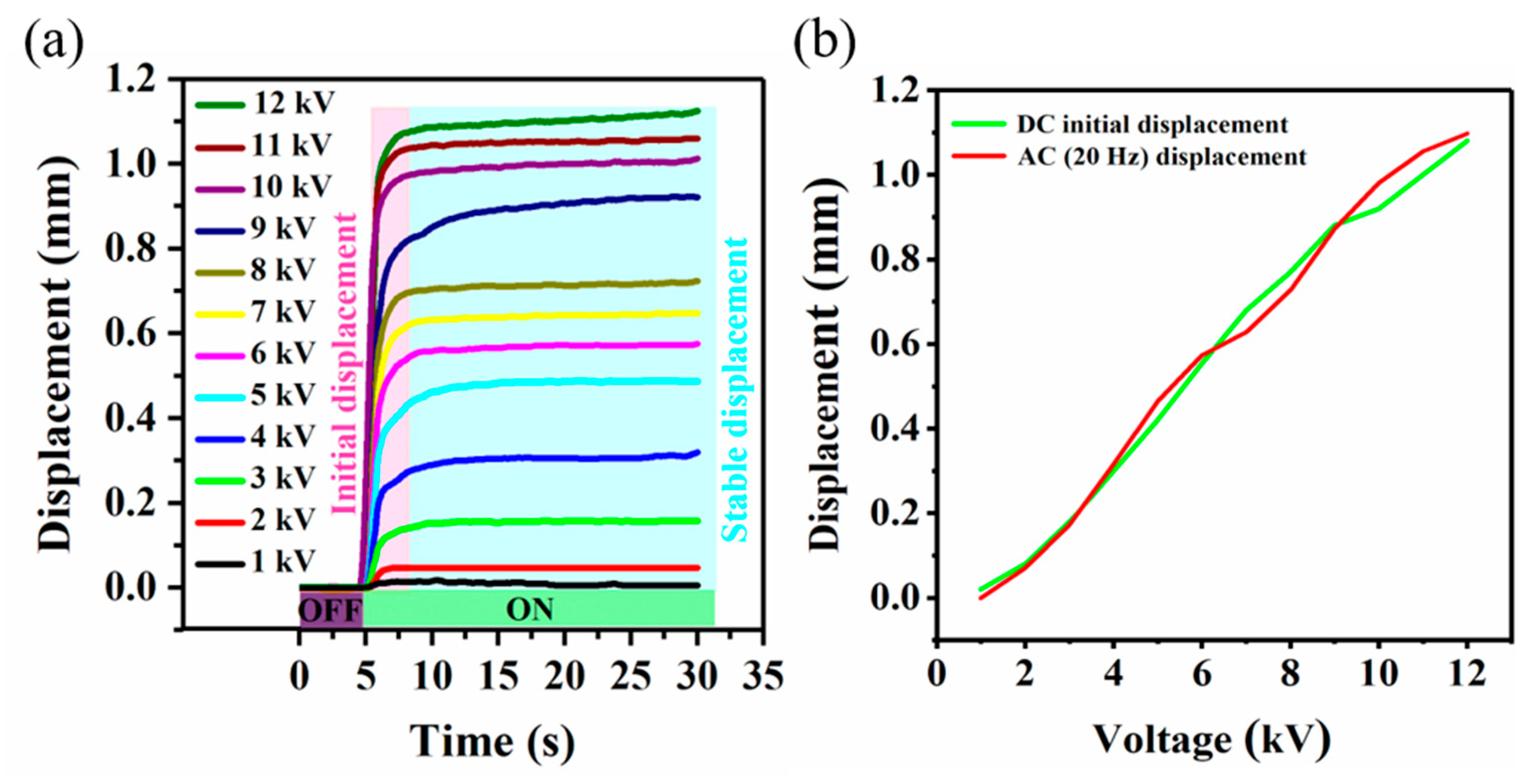
4.1. Output Performance of the Electro-Hydraulic Actuator

Single electro-hydraulic actuator at different DC and AC voltages is characterized using the test bench described in Section 3.2. A high-voltage generator (Model 20/20C-HS, Trek, USA) was applied to output voltages from 1 kV to 12 kV. In Figure 4, DC voltage loading starts from 3 s, and displacement occurs in an instant and drops rapidly with time [26]. The maximum measured displacement of 1.1 mm is obtained from 3 to 4 s at 12 kV, and decreases to 0.4 mm at 30 s. The reason for the decrease in displacement is that the central film accumulates a large restoring force while the displacement is instantaneously obtained. The restoring force acts on the electrodes through the liquid, which increases the distance between the electrodes and reduces the Maxwell force.
Figure 5a–c plots the displacement as a function of time with AC voltage with 10, 50, and 100 Hz. A smaller voltage frequency leads to a larger oscillation when the actuator outputs displacement. The voltage frequency has a significant influence on the oscillation of the displacement at low frequencies. Figure 5d plots the variance as a function of voltage frequencies from 1 to 100 Hz. The influence diminishes rapidly as the frequency increases and becomes smaller after the frequency reaches 20 Hz. The variance in the displacement value after a period of stability was used as a measure of displacement oscillation.
Figure 6 explains the reason for obtaining different results with the two loading methods. Under DC (11 kV) voltage loading, the maximum measured displacement of 1.0 mm is obtained in 0.15 s, which makes the central film produce a larger restoring force. The large restoring force drives the liquid to flow back rapidly, which causes the displacement to decay rapidly under the action of the Maxwell force and restoring force. Under AC (11 kV) voltage loading, the maximum measured displacement of 1.0 mm is obtained in 1 s. Different from the DC voltage, in this process, the displacement reaches a maximum after several times of rising, and each time there is still enough Maxwell force to overcome the smaller restoring force of the central film, which prevents the liquid from flowing back and allows the actuator to continue to produce displacement. The enlarge image from 5 s to 10 s in Figure 6 describes the process before the displacement of the actuator rises to a steady state when the AC voltage is applied. The displacement reaches its maximum after several oscillations. The enlarge image from 10 s to 15 s in Figure 6 shows the actuator after the output displacement is stabilized at an AC voltage of 5 Hz. After the displacement is stabilized, each oscillation is arranged regularly. In total, 25 oscillations occurring within 5 s were recorded, and the obtained cycle was consistent with the applied AC voltage cycle, which confirms that each oscillation on the graph represents the combined effect of the central film restoring force and the Maxwell force. Compared with the DC voltage, the AC voltage was applied to overcome a smaller restoring force of the central film many times, which produced a better result.
Based on the Maxwell force and hydraulic amplification principle, when DC voltage is applied, the displacement of the actuator will decrease, which is inevitable. The decrease in displacement with the DC voltage allows the user to obtain only a short feedback effect, while the AC voltage loading method can stably and continuously output displacement for the finger with different frequencies. Figure 7a plots the displacement as a function of time with AC voltage ranging from 1 to 12 kV. Voltage loading starts from 5 s. The displacement occurs in an instant and reaches a steady state within 3 s, without decreasing. Figure 7b shows the displacement obtained by different loading methods as a function of voltage. As the voltage changes, the displacement of the actuator under the two loading methods remains the same. The results show that the AC voltage maintains the output performance of the actuator while enabling the actuator to obtain a better output effect.
Human tactile sensation comes from the external stimulation of human skin receptors. Different types of human skin receptors have different sensory thresholds. Tactile experience is the coordinated response of many different types of nervous systems to pressure, temperature, pain, joint position, muscle perception and movement. The generation of tactile sensation requires the action of multiple receptors located in the skin. In the paper, the Merkel disc receptors are just stimulated, which are responsible for continuous touch and pressure perception that needs to be activated by stress. Activating the human finger’s sensory receptors for touch requires the corresponding pressure stimulation. In reality, the tactile feedback actuator needs to output pressure on the finger to activate the finger’s sensory threshold to reproduce the touch. When haptic feedback actuators are used in real situations, force and displacement are often required at the same time. In order to make the experiment accord with the actual use of the actuator, a load is placed in the center area of the actuator to simulate the contact with a human hand. Loads with different weights are made by Fused Deposition Modelling (FDM) and applied to simulate different contact pressure. Figure 8 plots the displacement as a function of load from 1 to 7 g. The output pressure of the actuator starts from 0 to a maximum of 1 N/cm2. The displacement decreases with increasing load. The maximum measured displacement of 0.15 mm is obtained from a load of 7 g.

4.2. Haptic Feedback Teleoperation System Based on the Electro-Hydraulic Actuator

According to the output characteristics of the actuator, a haptic feedback teleoperation system was designed [27,28]. As shown in Figure 9a,b, a high-voltage power supply is connected to the actuator through a high-voltage relay. A waveform generator (33500B Series, Keysight, Beijing, China) is used to generate a square waveform. An Arduino controller (Arduino uno, Tycorady industrial technologies, Beijing, China) controls the on–off of the high-voltage relay through an ordinary relay, and both the input of the high-voltage relay and the output of the ordinary relay are powered by a voltage of 12 V. A commercial tactile sensor is connected to the Arduino controller to collect and convert the analog signal of the acquired force into a digital signal.
As shown in Figure 10a, the haptic feedback system is mainly composed of an electro-hydraulic actuator, a fingertip sensor, and their interaction. The system is integrated into a commercial glove that controls a machine hand. The operator wears the haptic feedback glove and performs virtual grasping. The remote machine hand immediately executes the corresponding action after receiving the command. Once the machine hand grabs an object, the tactile sensor embedded in the finger of the machine hand collects the touch information and transmits it to the haptic feedback glove through the haptic feedback control system. Then, the haptic feedback actuator is controlled to output the corresponding force and displacement according to the touch information, providing a more realistic tactile impression to the operator.
During the grasping process, the output force of the actuator should be associated with the value obtained by the tactile sensor. Based on the previous research at Section 4.1, we have fitted the relationship between the applied voltage and the output displacement of the actuator in Figure 10b. The maximum displacement of the actuator is 1.1 mm. We set the force obtained by the sensor to be proportional to the output displacement of the actuator. According to the relationship between the force and the resistance of the sensor, the functional relationship between the resistance of the sensor and the applied voltage of the actuator can be determined and applied in the programs of the control system. As shown in Figure 10c, the user completes the process from the finger touching the object to leaving it within 1 s. The whole process is shown in Video S1. Different voltages can be applied to the actuator in the haptic feedback glove to achieve the purpose of outputting different forces and displacements, which could reproduce a more realistic touch between the fingers.
In the process of performing repeated grabbing tasks, for the same pressure signal output by the sensor multiple times, the actuator is required to accurately output the same displacement to ensure the authenticity of the feedback. Figure 11 describes the relationship between the number of cycles and the stable displacement under the same voltage. In Figure 10, the same voltage (12 kV, 20 Hz) was applied to the actuator for 50 consecutive times. The output displacement of the actuator is maintained at a stable value without significant changes. Figure 12 shows the performance of the actuator when it experiences periodic input voltage (12 kV, 20 Hz) for a long time under load. The periodic input voltage simulates the process of a robot continuously grabbing objects within 150 s. The actuator rapidly outputs displacement under load and remains stable within 3 s. After disconnecting the input voltage, the displacement of the actuator rapidly recovers and returns to its initial value within 3 s. Comparing the two periods at the beginning and end of the voltage loading, the output characteristics of the actuator remain consistent without decay, which proves the good reliability of the actuator when used in real conditions. The experimental results show that the actuator can stably output pressure and displacement for the finger and handle multiple and repeated touches for controlling the manipulator task when the actuator is used as a tactile feedback device.

5. Conclusions

We have proposed an electro-hydraulic actuator with a safety structure and excellent output characteristics suitable for wearable devices. Fully flexible materials are used to make the actuator easy to integrate into wearable devices, and the design of the electrode inside the actuator avoids direct contact between the user and the electrode, which makes the actuator safer for users. The influence of two different voltage loading methods on the output characteristics of the actuator was studied, and the advantages of AC voltage across a range of actuator characteristics were experimentally confirmed. A new voltage loading method (AC voltage) enables the actuator to respond rapidly, within 0.15 s, generate at the same time stable output displacement in 3 s, and remain unchanged in the subsequent time. By adjusting the voltages and frequencies, a maximum output displacement of 1.1 mm and an output force of 1 N/cm2 can be rapidly achieved at a voltage of 12 kV (20 Hz). Finally, a haptic feedback remote operation system was designed to verify that the actuator can be applied to wearable devices. The machine hand is controlled for different grasping tasks, and the actuator rapidly responds to the touch of the machine hand to achieve feedback; each time it made accurate displacement and force output for a continuous grasping action of 150 s. Although a high voltage was used on the actuator as the driving method, the structure of the built-in electrode allowed the electrode to be well wrapped by the actuator and not exposed, which can effectively prevent direct contact between the human hand and the electrodes. In the follow-up research, we will develop a more compact voltage-generating device, which can be carried around. This driving method will have broad prospects in future haptic feedback applications, as it allows developing actuators for true wearable devices and consumer products.

Supplementary Materials

The following are available online at https://www.mdpi.com/2076-3417/10/24/8827/s1, Video S1: The operation process of the haptic feedback teleoperation system.

Author Contributions

Conceptualization, P.W., Z.J., Y.Y. and W.Y.; methodology, X.C.; software, M.Y.; validation, J.M. and X.C.; formal analysis, J.M.; investigation, J.M.; resources, P.W. and Z.J.; data curation, B.L.; writing—original draft preparation, J.M.; writing—review and editing, X.C. and Z.J.; visualization, Y.Y.; supervision, P.W.; project administrat+ion, P.W. and Z.J.; funding acquisition, P.W., Z.J. and X.C. All authors have read and agreed to the published version of the manuscript.

Funding

The work was supported by National Natural Science Foundation of China (No. 51905530, 91748209, 51803010), China Postdoctoral Science Foundation (No. 2018M641440, 2019M660750), Beijing Nova Program from Beijing Municipal Science & Technology Commission (Z201100006820146), Guangdong Provincial Science and Technology Project (2016B090915001) and Zhuhai Industrial Core and Key Technology Research Project (ZH01084702180085HJL).

Conflicts of Interest

The authors declare no conflict of interest.

References

  1. Yu, X.; Xie, Z. Skin-integrated wireless haptic interfaces for virtual and augmented reality. Nature 2019, 575, 473–479. [Google Scholar] [CrossRef] [PubMed]
  2. Li, M.; Ranzani, T. Multi-fingered haptic palpation utilizing granular jamming stiffness feedback actuators. Smart Mater. Struct. 2014, 23, 095007. [Google Scholar] [CrossRef]
  3. Jung, H.-K.; Park, G. Structural impact detection with vibro-haptic interfaces. Smart Mater. Struct. 2016, 25, 075041. [Google Scholar] [CrossRef] [Green Version]
  4. Hwang, Y.-H.; Kang, S.-R. A robot-assisted cutting surgery of human-like tissues using a haptic master operated by magnetorheological clutches and brakes. Smart Mater. Struct. 2019, 28, 065016. [Google Scholar] [CrossRef]
  5. Choi, S.-H.; Kim, S. A new visual feedback-based magnetorheological haptic master for robot-assisted minimally invasive surgery. Smart Mater. Struct. 2015, 24, 065015. [Google Scholar] [CrossRef]
  6. Lee, H.-J.; Loh, K.J. Soft material actuation by atomization. Smart Mater. Struct. 2019, 28, 025030. [Google Scholar] [CrossRef]
  7. Sun, J.Y.; Keplinger, C. Ionic skin. Adv. Mater. 2015, 26, 7608–7614. [Google Scholar] [CrossRef]
  8. Martinez, R.V.; Branch, J.L. Robotic Tentacles with Three-Dimensional Mobility Based on Flexible Elastomers. Adv. Mater. 2013, 25, 205–212. [Google Scholar] [CrossRef] [PubMed]
  9. Miriyev, A.; Stack, K. Soft material for soft actuators. Nat. Commun. 2017, 8, 596. [Google Scholar] [CrossRef] [PubMed]
  10. Tsugawa, M.A.; Palmre, V. Slender tube-shaped and square rod-shaped IPMC actuators with integrated sensing for soft mechatronics. Nat. Commun. 2015, 50, 2781–2795. [Google Scholar] [CrossRef]
  11. Polygerinos, P.; Correll, N. Soft Robotics: Review of Fluid-Driven Intrinsically Soft Devices Manufacturing, Sensing, Control, and Applications in Human-Robot Interaction. Adv. Eng. Mater. 2017, 19, 1700016. [Google Scholar] [CrossRef]
  12. Yeo, J.C.; Yap, H.K. Flexible and Stretchable Strain Sensing Actuator for Wearable Soft Robotic Applications. Adv. Mater. Technol. 2016, 1, 1600018. [Google Scholar] [CrossRef]
  13. Saurabh, J.; Vikas, K. Soft robotic glove for kinesthetic haptic feedback in virtual reality environments. Electron. Imaging 2017, 3, 19–24. [Google Scholar]
  14. Chossat, J.B.; Chen, D.K.Y. Soft Wearable Skin-Stretch Device for Haptic Feedback Using Twisted and Coiled Polymer Actuators. IEEE Trans. Haptics 2019, 12, 521–532. [Google Scholar] [CrossRef]
  15. Kim, M.; Jeon, C. A Study on Immersion and Presence of a Portable Hand Haptic System for Immersive Virtual Reality. Sensors 2017, 17, 1141. [Google Scholar]
  16. Song, K.; Kim, S.H. Pneumatic actuator and flexible piezoelectric sensor for soft virtual reality glove system. Sci. Rep. 2019, 9, 1–8. [Google Scholar] [CrossRef] [Green Version]
  17. Hou, S.; Wang, M. Photothermally Driven Refreshable Microactuators Based on Graphene Oxide Doped Paraffin. ACS Appl. Mater. Interfaces 2017, 9, 26476–26482. [Google Scholar] [CrossRef]
  18. Kwon, H.-J.; Lee, S.W. Braille dot display module with a PDMS membrane driven by a thermopneumatic actuator. Sens. Actuator A Phys. 2008, 154, 238–246. [Google Scholar] [CrossRef]
  19. Lee, H.S.; Phung, H. Design analysis and fabrication of arrayed tactile display based on dielectric elastomer actuator. Sens. Actuator A Phys. 2014, 205, 191–198. [Google Scholar] [CrossRef]
  20. Chakraborti, P.; Toprakci, H.A.K. A compact dielectric elastomer tubular actuator for refreshable Braille displays. Sens. Actuator A Phys. 2012, 179, 151–157. [Google Scholar] [CrossRef]
  21. Carpi, F.; Frediani, G. Hydrostatically Coupled Dielectric Elastomer Actuators. IEEE-Asme Mech. 2010, 15, 308–315. [Google Scholar] [CrossRef]
  22. Frediani, G.; Mazzei, D. Wearable wireless tactile display for virtual interactions with soft bodies. Front. Bioeng. Biotech. 2014, 2, 31. [Google Scholar] [CrossRef] [PubMed] [Green Version]
  23. Acome, E.; Mitchell, S.K. Hydraulically amplified self-healing electrostatic actuators with muscle-like performance. Science 2018, 359, 61–65. [Google Scholar] [CrossRef] [PubMed] [Green Version]
  24. Kellaris, N.; Venkata, V.G. An analytical model for the design of Peano-HASEL actuators with drastically improved performance. Exterme Mech. Lett. 2019, 29, 100449. [Google Scholar] [CrossRef]
  25. Guo, W.; Wang, X. Plant oil and amino acid-derived elastomers with rapid room temperature self-healing ability. J. Mater. Chem. A 2019, 7, 21927–21933. [Google Scholar] [CrossRef]
  26. Nakamura, T.; Yamamoto, A. Modeling and control of electroadhesion force in DC voltage. Robomech. J. 2017, 4, 18. [Google Scholar] [CrossRef]
  27. Lee, S.-R.; Choi, S.-H. Design of a smart haptic system for repulsive force control under irregular manipulation environment. Smart Mater. Struct. 2014, 23, 125040. [Google Scholar] [CrossRef]
  28. Tzafestas, C.S. Whole-hand kinesthetic feedback and haptic perception in dextrous virtual manipulation. IEEE Trans. Syst. ManCybern. Part A Syst. Hum. 2003, 33, 100–113. [Google Scholar] [CrossRef] [Green Version]
Figure 1. The composition of the electro-hydraulic haptic feedback actuator.
Applsci 10 08827 g001
Figure 2. Schematic diagram of the electro-hydraulic haptic feedback actuator with (a) Voltage OFF and (c) Voltage ON. (b) The action principle of the actuator. (d) Cross section of the actuator before and after power on.
Applsci 10 08827 g002
Figure 3. The preparation process of the electro-hydraulic haptic feedback actuator. (a) The mixture is cast into the mold. (b) The prepared PDMS film is laser cut into specific shapes. (c) The conductive tape is laser cut into a specific shape. (d) The layers of the actuator are respectively glued from the bottom to the top. (e) Ecoflex-0030 is injected on the edge of the actuator. (f) The insulating oil is injected into the actuator through Ecoflex-0030.
Applsci 10 08827 g003
Figure 4. The output displacement of the actuator under different DC voltages over time.
Applsci 10 08827 g004
Figure 5. The oscillation of the output displacement of the actuator under the square wave voltage with the same amplitude of 12 kV and different frequencies of (a) 10 Hz, (b) 50 Hz, (c) 100 Hz, respectively. (d) The variance of the output displacement of the actuator under a square wave voltage (12 kV) with different frequencies (1–100 Hz).
Applsci 10 08827 g005
Figure 6. The output characteristics of the actuator under DC and AC voltages are compared.
Applsci 10 08827 g006
Figure 7. (a) Output displacement of the actuator under 20 Hz-square wave voltages over time. (b) Dependence of the stable output displacement of the actuator on DC and AC voltages.
Applsci 10 08827 g007
Figure 8. The stable output displacement of the actuator under loads from 1 g to 7 g and square wave voltages from 6 kV to 13 kV (20 Hz).
Applsci 10 08827 g008
Figure 9. Haptic feedback control system with schematic diagram (a) and the photo (b).
Applsci 10 08827 g009
Figure 10. (a) Schematic diagram of the haptic feedback teleoperation system. (b) Displacement of the actuator as a function of electric field. (c) The operation process of the haptic feedback teleoperation system.
Applsci 10 08827 g010
Figure 11. The relationship between the number of cycles and the stable displacement under the same voltage (12 kV, 20 Hz).
Applsci 10 08827 g011
Figure 12. The performance of the actuator when it experiences periodic input voltage (12 kV, 20 Hz) for a long time under load.
Applsci 10 08827 g012
Publisher’s Note: MDPI stays neutral with regard to jurisdictional claims in published maps and institutional affiliations.

