Article

Modeling Analysis of Thermal Lesion Characteristics of Unipolar/Bipolar Ablation Using Circumferential Multipolar Catheter

1
Department of Electronic Engineering and Academy for Engineering & Technology, Fudan University, Shanghai 200438, China
2
Key Laboratory of Medical Imaging Computing and Computer Assisted Intervention (MICCAI) of Shanghai, Shanghai 200433, China
3
Shanghai Engineering Research Center of Assistive Devices and Department of Electronic Engineering, Fudan University, Shanghai 200093, China
*
Authors to whom correspondence should be addressed.
Appl. Sci. 2020, 10(24), 9081; https://doi.org/10.3390/app10249081
Submission received: 26 October 2020 / Revised: 4 December 2020 / Accepted: 15 December 2020 / Published: 18 December 2020
(This article belongs to the Special Issue State of the Art and New Trends in Biomedical Engineering)

Abstract

:
The circumferential multipolar catheter (CMC) facilitates pulmonary vein isolation (PVI) for the treatment of atrial fibrillation by catheter ablation. However, the ablation characteristics of CMC are not well understood. This study uses the finite element method to conduct a comprehensive analysis of the ablation characteristics of multielectrode unipolar/bipolar (MEU/MEB) modes of the CMC. A three-dimensional computational model of the CMC, including blood, myocardium, connective tissue, lung, and muscle, was constructed. The method was validated by comparing the results of an in vitro experiment with the simulation. Both ablation modes could create contiguous effective lesions, but the MEU mode created a deeper and broader lesion volume than the MEB mode. The MEB mode had an overall higher average temperature field and allowed faster formation of the effective contiguous lesion. The lesion shape tended to be symmetric and spread downward and superficially in the MEU mode and MEB mode, respectively. Results from the simulation for validation agreed with the in vitro experiment. Different ablation trends of the MEU and MEB modes provide different solutions for specific ablation requirements in clinical applications. The MEU mode suits transmural lesion in thick tissue around pulmonary veins (PVs). The MEB mode profits fast and durable creation of circumferential PVI. This study provides a detailed performance analysis of CMC, thereby contributing to the theoretical knowledge base of application of PVI with this emerging technology.

1. Introduction

Atrial fibrillation (AF) is the most prevalent form of cardiac arrhythmia owing to its significant morbidity and mortality, affecting more than 30 million individuals worldwide [1,2,3]. AF patients not only suffer from irregular heartbeats but also are at risk for various associated complications, such as stroke, heart failure, and coronary syndrome [4].
Radiofrequency catheter ablation (RFCA) is a promising and safe medical modality to ease or eliminate AF-induced burden with the application of radiofrequency (RF) power. It entails irreversible necrosis of cardiac tissue performed by an ablation catheter that is delivered percutaneously to the target site [5,6]. For decades, circumferential pulmonary vein isolation (PVI) has been the cornerstone for AF treatment [7]. As a traditional method to carry out PVI, point-by-point ablation is widely used [8,9]. However, according to reports, its long-term efficiency is unsatisfactory because the procedure is complicated and time-consuming. In addition, contiguous and transmural tissue damage is difficult for a single-tip catheter to achieve [10]. Therefore, circumferential multipolar catheters (CMCs) such as the pulmonary vein ablation catheter (PVAC, Medtronic Inc., Minneapolis, MN, USA) [11] and the multipolar irrigated radiofrequency ablation catheter (nMARQ, Biosense Webster, Inc., Diamond Bar, CA, USA) [12] have been created to achieve complete PVI through a single application of RFCA. These so-called single-shot catheters need to be tailored to fit the anatomy of the antral part of PVs for ablation activity. Therefore, they are configured with a circular geometry.
The effectiveness of CMC for PVI has been proven in previous studies [13,14,15,16,17]. With multiple active electrodes, both PVAC and nMARQ enabled the delivery of RF power in the unipolar and bipolar modes [10]. However, those studies focused on examining the clinical accuracy and success rate only. There are few detailed studies that explicitly analyze lesion characteristics and the differences arising from unipolar and bipolar modes of CMC.
Considering its unique configuration, the CMC should exhibit distinct ablation performance compared to conventional single-tip and multipolar catheters in a linear structure. The electrical and thermal properties of these two catheters have been studied theoretically via computational simulation, which is a time-efficient and cost-effective technique [18,19,20]. The role of the simulation study is to provide the theoretical basis of ablation behavior and to clinically assist with personalized therapeutic schedules for individual patients [18]. Accordingly, the objective of this study is to explore the detailed ablation behavior of the multielectrode unipolar (MEU) and multielectrode bipolar (MEB) modes of CMC using a three-dimensional computational model of RFCA and the finite element method. The ablation model was validated by comparing the ablation results of the experiment with the computational simulation.

2. Materials and Methods

2.1. Governing Equation

The common model used to describe heat transfer in biological tissue is the Pennes bioheat transfer equation, which is given as [21]:
ρ   c   T t = 𝛻 · ( k   𝛻   T ) Q p + Q m + Q h ,
where ρ is the tissue density (kg m−3), c is the specific heat of tissue at constant pressure (J kg−1 K−1), T is the temperature of tissue (K), and k is the thermal conductivity of the biological tissue (W m−1 K−1). QP is the heat loss due to blood perfusion (W m−3), Qm is the volumetric heat produced by metabolism (W m−3), and Qh is the heat source generated by the RF current (W m−3) from the active electrodes. Generally, the terms Qp and Qm are ignored because of their insignificant contributions to cardiac ablation, compared with the other terms in the Pennes equation [21]. In the RF range used in cardiac ablation (approximately 500 kHz), the biological tissue can be considered as a total resistive medium. The heat source Qh refers to Joule heating and can be expressed by solving the quasistatic electrical problem
Q h = σ | E | 2 ,
where σ is the electrical conductivity (S m−1) of the biological tissue; and E = V is the electric field intensity (V m−1), which is calculated from the gradient of the associated electric potential V (V). If no internal electric sources exist in the heat transfer system, the electric potential V will satisfy:
𝛻 · σ   𝛻   V = 0 ,
The application of RF power inflicts irreversible lesions on the biological tissue. Previous studies concluded that the temperature field enclosed by the 50 °C isothermal surface after ablation activity reflects the effective lesion volume [19,20].

2.2. Construction of Ablation Model

Two computational models for experimental validation and a comprehensive simulation study were constructed on COMSOL Multiphysics 5.4 software (COMSOL, Burlington, MA, USA). For both the cases, a catheter model was built on SOLIDWORKS (Dassault Systèmes SolidWorks Co., Waltham, MA, USA), and its geometry and dimensions were modeled after the device used at St. Jude Medical Inc. The model of the comprehensive simulation study consisted of a blood chamber, a slab of the myocardium, connective tissue, lung, and muscle from top to bottom, as illustrated in Figure 1. A circumferential decapolar (10 electrodes) ablation catheter was located perpendicular to the myocardium at the center of the model. The catheter penetrated the myocardium at a depth of 0.1 mm. The thicknesses of blood, myocardium, connective tissue, and muscle were configured to 9 mm, 5 mm [19,20], 2 mm [22], and 18 mm [23], respectively. The thickness of the lung region (Z), length (X), and width (Y) of the entire model were obtained from a convergence test to avoid boundary effects. The maximum temperature in the myocardium after 60 s of RFCA was used as the control parameter of the test. The spatial and temporal resolutions were considered tentative. The appropriate values of X, Y, and Z were determined by equally increasing their values by 5 mm per step. When the two resulting maximum temperature values in consecutive simulations have a difference of less than 0.5%, the former set of dimensions is applicable. The model for the experimental validation is detailed in Section 2.4.

2.3. Material Properties and Boundary Conditions

The thermal and electrical properties of materials used in the ablation model are listed in Table 1 [22,24,25,26,27]. The values of the electrical and thermal conductivities of the myocardium shown in Table 1 were assessed at an ambient temperature of 37 °C. These two parameters are temperature-dependent and follow unique piecewise relations [19,20]. The electrical conductivity increased exponentially at a rate of 1.5% °C−1 below 100 °C and then dropped by four orders of magnitude between 100 °C and 105 °C. The thermal conductivity increased linearly at a rate of 0.12% °C−1 up to 100 °C and remained constant thereafter.
Figure 2 displays the electrical and thermal boundary conditions of the MEU and MEB modes. For the MEU mode, each electrode was applied with a constant power of 20 W. The bottom surface of the model had a rating of 0 V, acting as the ground pad or dispersive electrode. The RF current in this configuration was driven between the active and dispersive electrodes. For the MEB mode, the power and the voltages on every two non-overlapping electrodes in sequence (i.e., Electrode 1 and Electrode 2, Electrodes 3 and 4, etc.) were set to 10 W and 0 V, respectively. The RF current was forced to flow between the adjacent electrodes with different applied powers. A control algorithm was introduced for the applied power source in case of overheating. It was implemented by a step function with a starting level referring to the power required for each ablation mode and a final level of 0 in amplitude. The maximum resulting temperature in the myocardium was inspected and could be held around a temperature threshold of 95 °C, which was set as the position of the step.
A constant temperature of 37 °C was applied to all boundaries of the model. The effect of blood flowing inside the atrium was modeled by two thermal convection coefficients at the electrode–blood interface, hE = 3636 W m−1 K−1, and the tissue–blood interface, hT = 708 W m−1 K−1, which were calculated under a medium flow condition of 10.3 cm s−1 [21].

2.4. Validation of Simulation Method

To ensure the feasibility and correctness of the simulation and modeling method, we performed an in vitro experiment and compared the dimensions of the temperature field generated on the tissue surface with the simulation results. The experimental equipment and the demonstration of the model with boundary conditions are demonstrated in Supplementary Figure S1. We experimented with the electrodes in the MEU and MEB modes. Each setting was implemented on a piece of fresh porcine cardiac tissue (sourced from the local food market) that was cut approximately in a uniform size of 40 mm × 50 mm × 6 mm. The CMC was connected to an RF generator and placed perpendicular to the myocardium. The insertion depth of the CMC was 0.5 mm. A slice of aluminum foil beneath the myocardium was used as the ground pad in the MEU mode. The RF generator provided a voltage source of 25 V. All temperature fields were imaged using a FLUKE Ti32 thermal imager (FLUKE Co., Everett, WA, USA) with emissivity of 0.99. A model of the porcine tissue with the same dimensions was simulated for comparison. The ablation period was set to 10 s in both cases. As we did not implement the blood circulating in the experiment, we did not consider the thermal convections in the simulation for validation. Given the possibility of delays and discrepancies in the temperature response of the thermal imager, the actual temperature recorded during the experiment was chosen as the initial temperature of the porcine tissue in the simulation.

3. Results

The dimensions of the model were X = Y = 100 mm and Z = 60 mm after the convergence test. The electrode–tissue interface was meshed with a minimum element size of 0.1 mm. The time step was set to 0.1 s. Simulation time for both the two ablation modes was 60 s. The entire model had 405 402 tetrahedral elements.

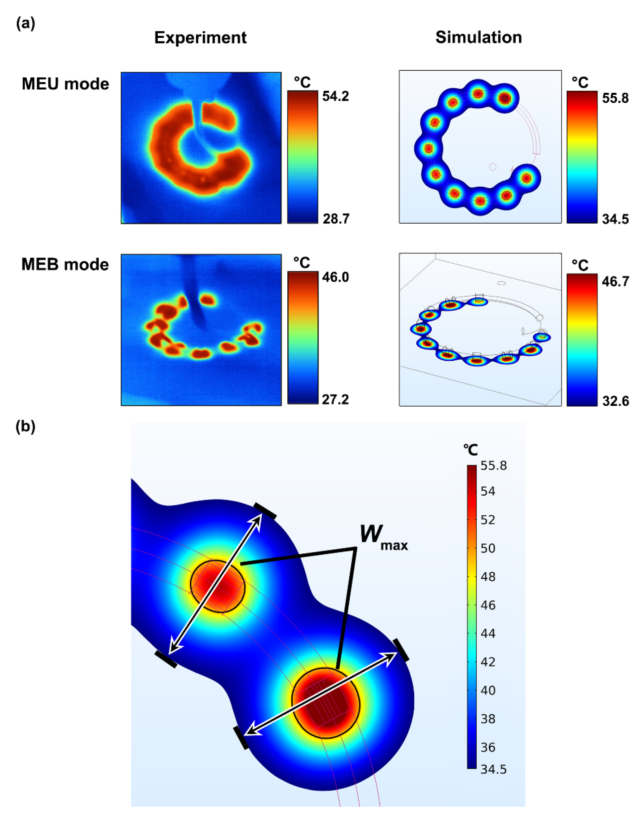
3.1. Experimental Validation

We focused on the lesion morphology and the maximum temperature difference reached in the experiment and simulation. Figure 3a illustrates the temperature fields recorded by the thermal imager and the simulations for the MEU and MEB modes at 10 s of RFCA. The morphologies of the temperature fields in the experiment and simulation agreed closely. The maximum temperatures reached in the stimulations were relatively higher, but the occupancies of the highest temperature field in each mode were less than those in the experiment. Because the temperature (green zone in the image) from the experimental result in each mode acted as an obvious borderline separating the red and blue zones of the temperature distribution, we chose this temperature and set it as the minimum value in the simulation result. Based on this adjustment, we defined and measured the maximum width Wmax of the temperature field on the tissue surface generated by each electrode, as shown in Figure 3b. Table 2 compares the width Wmax of the experiment and the simulation. The maximum temperature differences between the experiment and the simulation were 2.9% and 1.5% for the MEU and MEB modes, respectively. The temperature field under each active electrode in the MEU mode merged and formed an arch-shaped damaged path. The lesion produced by the MEB mode was smaller and narrower, and it closely resembled a series of individual temperature zones around each electrode, with only a small interconnection between adjacent electrodes.

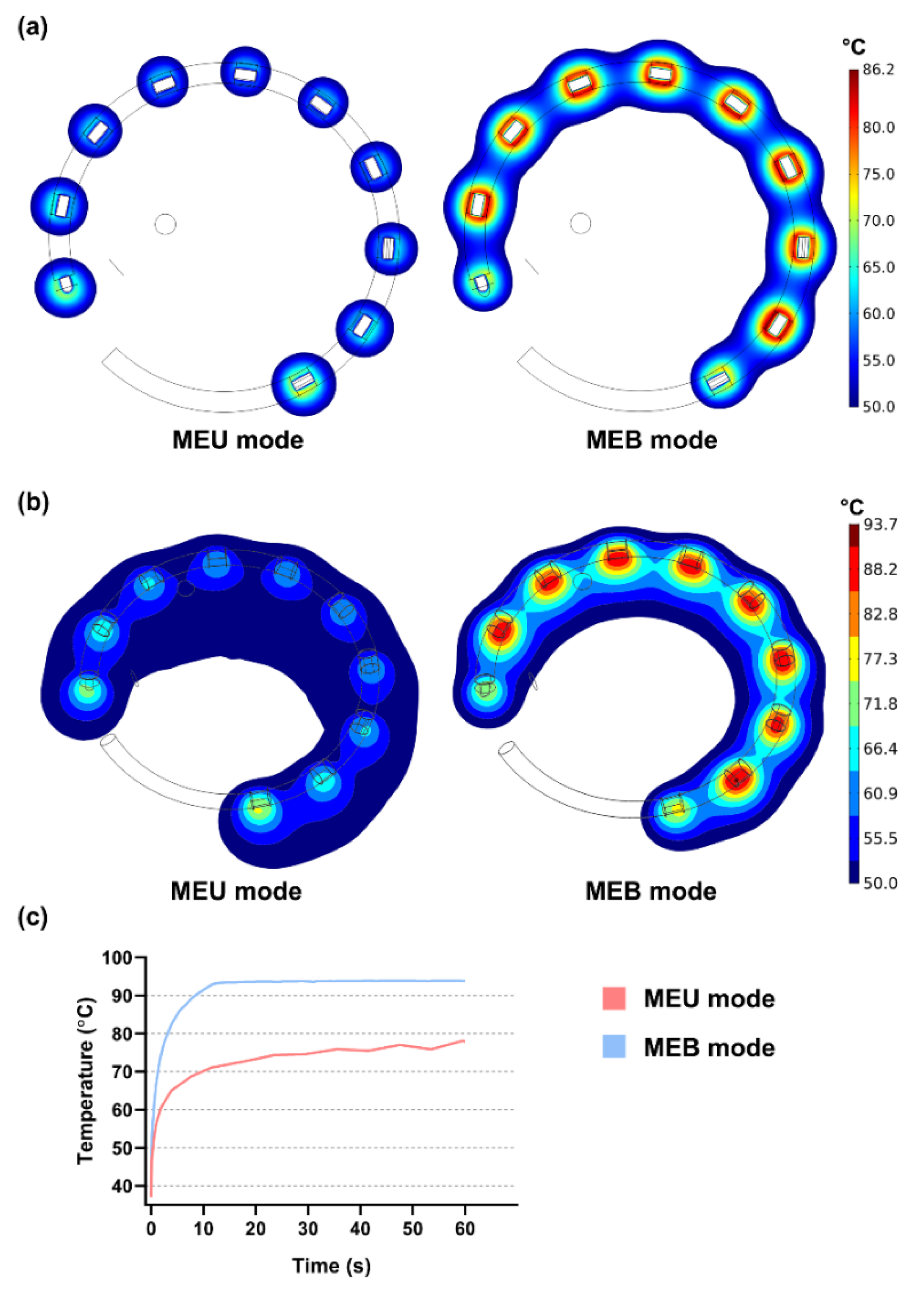
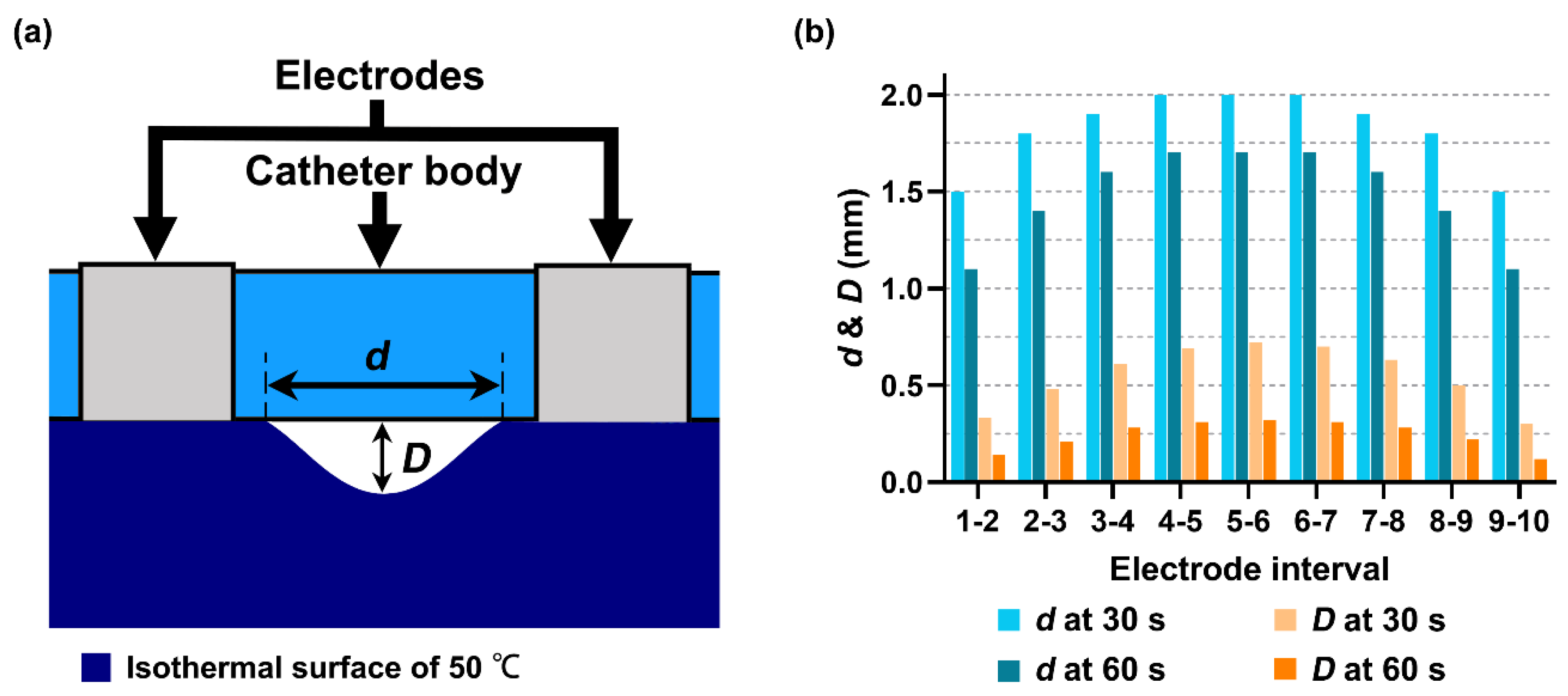
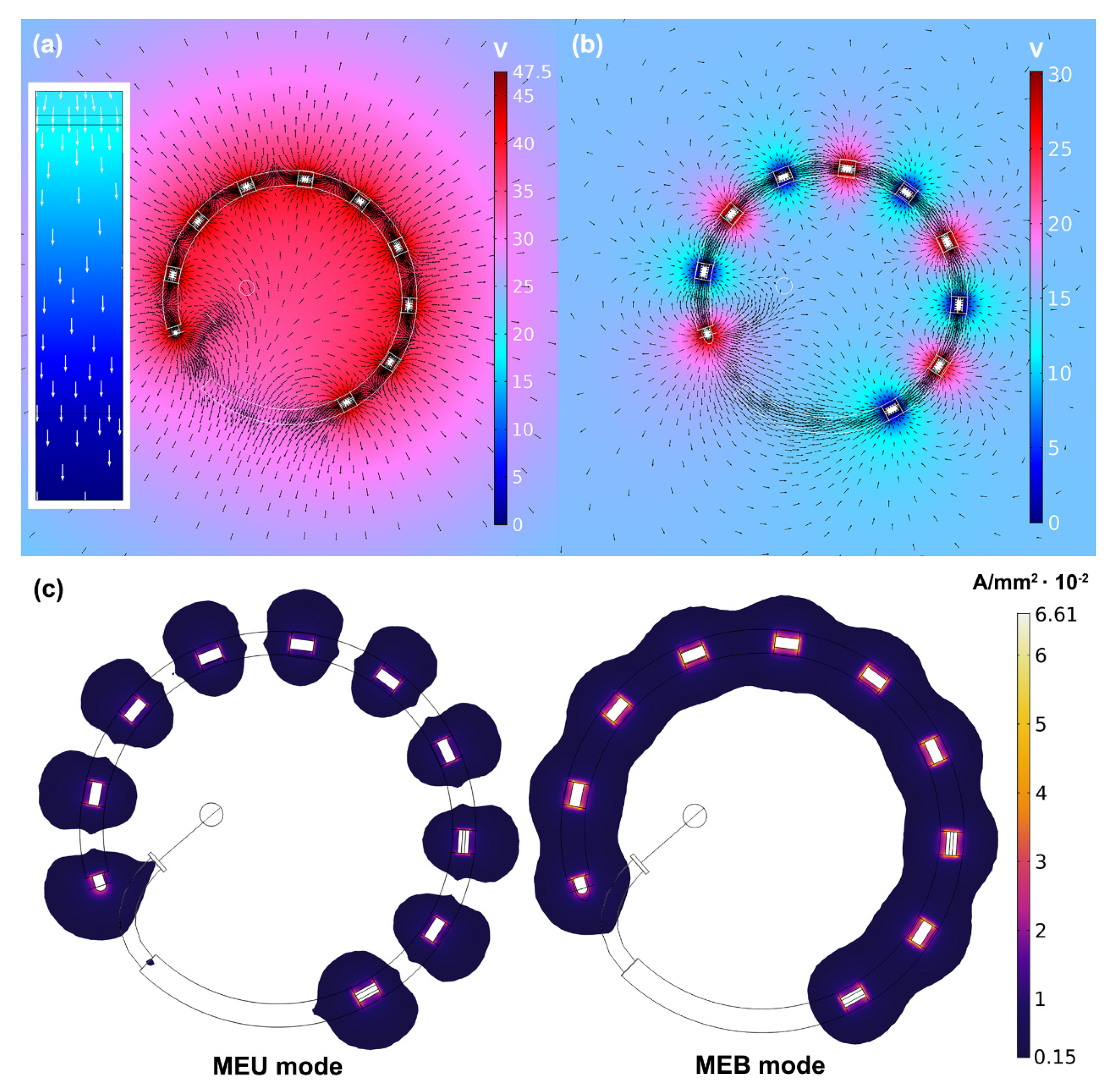
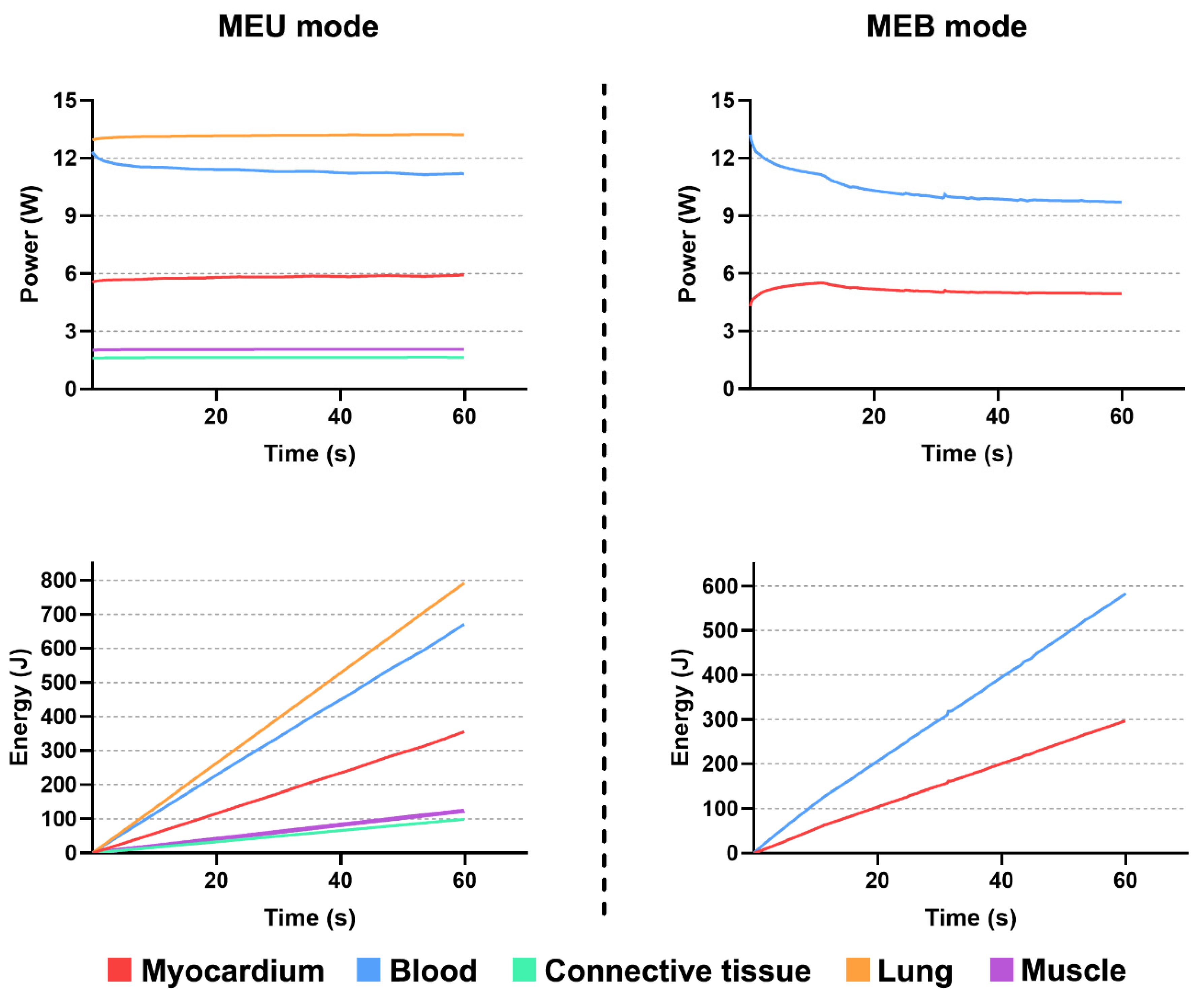
3.2. Performances of Multielectrode Unipolar (MEU) and Multielectrode Bipolar (MEB) Modes

All temperature distributions obtained from the comprehensive simulation study were bound by the 50 °C isothermal surface; thus, only the effective thermal lesion is considered hereafter.
Supplementary Figure S2 illustrates the process of lesion growth in the myocardium in the MEU and MEB modes at four time points during RFCA, until a preliminary effective continuous lesion was created. The overall thermal damage to the insides of the myocardium was achieved by spreading and merging the respective lesion under each electrode. In the MEU mode, the lesion began to form from the outer edge of each electrode. In the MEB mode, the lesion first appeared at the two sides that connected the electrode and catheter body. The time required for an effective continuous lesion in the MEB mode was 4.5 s, while that for the MEU mode was 25.6 s. Electrodes 1 and 10 in the MEU mode were the first two electrodes that merged their lesions with neighboring electrodes, but the last two to achieve the same in the MEB mode.
Figure 4a,b present the surface and internal temperature distributions of the myocardium in the MEU and MEB modes at 60 s of RFCA. Only the MEB mode could produce continuous lesions both on the tissue surface and inside the myocardium. The surface lesion was discontinuous and shaped like circles in the MEU mode. In both modes, the surface temperature was always lower than the temperature inside the myocardium, resulting from the thermal convection brought by blood flow. From Figure 4c, the temperature in the myocardium increased sharply in the MEB mode. The control algorithm worked properly that maintain the maximum temperature around 95 °C. We identified a concave region between the adjacent active electrodes in the MEU mode, as shown in Figure 5a. We noted the minimum distance d between every two peaks of the lesion on the tissue surface and the depth of concave D at 30 s and 60 s of RFCA, respectively (Figure 5b). The gap and the concave area increased from the two ends to the middle of the catheter. At 60 s of RFCA, the effect of D is small, but discontinuous lesions still exist between the adjacent electrodes on the tissue surface. For the MEB mode, we found no such evidence of a concave.
The highest surface temperatures in the MEU and MEB modes were generated at the outer edge of electrode 10 and the inner edge of electrode 9, respectively. A higher temperature field always occurs at the outer area of an electrode in the MEU mode and the inner area of the electrode in the MEB mode. This finding matched the current flow and the subsequent distribution of current density in both modes, as shown in Figure 6, in which the voltage distribution is also displayed. The current in both modes flowed spatially throughout the entire model. As indicated in Figure 6a, most of the current in the MEU mode spread out from the active electrodes and pointed outward to the dispersive electrode along the surrounding edges of the model bottom. A portion of the current gathered near a particular section of the catheter body and headed either to the above or below the blood chamber but eventually flowed toward the dispersive electrode. In addition, the areas between the adjacent electrodes were barely involved in current flows. As shown in Figure 6b, the current in the MEB mode splits out from the middle of each active electrode and flows toward the adjacent grounding electrodes. Current flows were more concentrated along the inner edge of the CMC, except for the transmission between electrodes 1 and 10.
According to the routes of current flow, the distribution of current density was generally discontinuous in the MEU mode between adjacent electrodes. The outer side of each electrode was occupied by more extensive areas of current density that formed a fan-shaped region. Owing to the gap in current density between adjacent electrodes on the tissue surface, the temperature at the two sides, especially the four corners of the electrode, was weak in the MEU mode. The MEB mode had a continuous distribution of current density along the circular catheter. The current density field vastly expanded at the inner edge of the CMC. Adjacent electrodes shared a connection between current density fields, responding to continuous lesions. The joint between the electrode and the catheter body was characterized by a higher current density in both modes. Furthermore, the current density of electrode 1 was cut off at the edge of the catheter body. Because the catheter body had extremely low electrical conductivity, it functioned as a barrier blocking the current flow. Electrode 10 had a broader distribution of current density along the catheter body without electrodes in the MEU mode.
Figure 7 displays the maximum lesion depth, temperature, and time required for effective lesion generation by each electrode, as well as the total lesion volume in the myocardium in the MEU and MEB modes. Electrodes 1 and 10 were the first two electrodes to generate effective lesions in the MEU mode but the last two electrodes in the MEB mode. Under the same RFCA period, faster heat generation of the electrode led to higher temperatures in both ablation modes. In the MEB mode, the lesion deepened with the increase in temperature. In the MEU mode, however, this finding was only established during the first 30 s of RFCA. For the subsequent 30 s, the electrode that previously generated a lower temperature produced deeper lesions. The lesion depth in the MEU mode at 60 s was 6.35 ± 0.87 mm, which is almost twice that in the MEB mode (3.39 ± 0.29 mm). Although the applied RF power in the MEB mode was half of that in the MEU mode, the average temperature of the MEB mode was 88.6 ± 5.8 °C, which was nearly 20 °C higher than that of the MEU mode. A notable phenomenon was captured in the MEU mode, where the lesion depth increased by approximately 3.80 mm during the subsequent 30 s of RFCA. For both modes, the maximum lesion depth, and generation time presented by 10 electrodes appeared to be a symmetric combination. The maximum temperature under each electrode fluctuated in the MEB mode. The lesion volume at 60 s of RFCA reached 831.36 mm3 and 479.59 mm3 in the MEU and MEB modes, respectively, as shown in Figure 7d. The MEB mode presented a rapid initial increase in lesion volume, but the rate of increase progressively decayed over time. For the MEU mode, a turning point appeared around 50 s at which the lesion volume started to increase sharply, which is probably the outcome of the aforementioned boost in lesion depth.
We also measured the surface lesion area, the maximum sectional lesion area of the myocardium, and the corresponding depth to approach the section at 30 s and 60 s of RFCA in Table 3. The results reflect that lesions spread principally from electrode to electrode as opposed to spreading in depth.
The corresponding power generation and heat energy absorption in different materials for the two ablation models are illustrated in Figure 8. As the current seldom flowed toward the deeper region of the model in the MEB mode, the power generated in the connective tissue, lung, and muscle was extremely low (average 2.34 × 10⁻³ W, 1.31 × 10⁻³ W, and 7.67 × 10⁻⁶ W, respectively); therefore, this was ignored in the result. The decreasing trend of the power in the myocardium of the MEB mode was believed to be caused by the temperature control. Since blood is more electrically conductive than the myocardium, more power and energy are consumed by the blood in both ablation modes. The consumption was even more severe in the lung region in the MEU mode.

4. Discussion

4.1. Main Findings

This study comprehensively analyzed the ablation characteristics of the MEU and MEB modes of a CMC. A mapping catheter was used herein because of the commercial restriction on procuring regular CMCs for ablation research in China. We modified the mapping catheter to perform the ablation activity. The purpose of the experimental validation was to justify the ablation model by achieving a close agreement between the experimental and the simulation results; hence, the experiment environment and the ablation conditions were irrelevant. Apart from the many intrinsic deviations due to the anisotropic structure of the porcine tissue and the electrode contact, the dissimilarities in lesion morphology and temperature might be a consequence of the irregular shape of the porcine tissue and possible dissimilarity parameters of physical properties between the real and in silico myocardium. The large-scale expansion of the high-temperature field was partly deemed the creation of bubbles on the tissue surface during ablation, which were likely to be rather hot. The recordings from the thermal imager were also not accurate because of calibration and capturing a delay or potential deficiency. Above all, we believe that the experimental validation is reasonable, and our simulated modality is qualified for the comprehensive simulation research.
Supplementary Figure S3 illustrates a standard ablation catheter from Biosense Webster [28], with three cases of simulation for its MEU and MEB performances. The simulation was performed based on a method like that described in Section 2.2. The MEU and MEB modes of the ablation catheter behaved in accordance with our previous findings, despite the different achievements of individual electrodes. The morphology of lesion depth and the overall variation trend of maximum temperature were like those obtained before. As the dimension of the conventional ablation catheter is larger than the one employed in this study, it is reasonable that the maximum lesion depth is fully enlarged, whereas the maximum temperature of each active electrode is lower than the former model as a result of a higher current density over a smaller field for a fixed applied RF power. The dimensions of ablation catheters, such as PVAC and nMARQ, are distinct [11,12]. However, we inferred from the comparison that the lesion features of the MEU and MEB modes are shared by all types of multielectrode ablation catheters to a large extent. The only uncertainty is in the variation of lesion size with the dimension and the number of electrodes, as well as the diameter of the helical CMC component of the CMC. Overall, the results of this study can meaningfully explain the lesion characteristics of the MEU and MEB modes.
The simulation results show that it is difficult to achieve continuous lesions with the MEU mode on the tissue surface and high temperature, even with a relatively higher RF power. However, the MEU mode has a notable deep lesion path inside the myocardium because the current is guided to flow toward the dispersive electrode, which is situated at the bottom far from the active electrodes. Additionally, a broad and wide lesion volume in the MEU mode may have been caused by the large occupation of the dispersive electrode that directed the heat propagation in a wide radial path. The increase in lesion depth and volume may have been the effect of conductive heating, which transfers energy into the deeper tissue [29].
In regard to ablation outcome, the CMC cannot be operated purely in the MEU mode because its performance chiefly relies on the electrical and thermal conductivities of the media (from cardiac tissue to skin) and the distance between the active and dispersive electrodes. A satisfying outcome of the MEU mode also depends on the premise that sufficient ablation time [30] and RF power are permitted, as plenty of power and energy are consumed in areas other than the myocardium. By contrast, the MEB mode is not influenced by external factors in any meaningful way, which causes faster temperature growth and lesion formation even under a lower applied RF power. For a single active electrode in the MEB mode, the generated current is guided by the adjacent grounding electrodes. Consequently, the current density converges around each electrode, and the lesion has a stronger impact in the region close to the surface of the cardiac tissue. In this study, the application of the RF power of 10 W in the MEB mode reached the temperature threshold in about 12 s, and the subsequent increase in the applied power in the MEB mode would easily allow the temperature to exceed 100 °C if the control algorism was not activated. Therefore, the maximum power for the MEB mode must be restrained to a lower level than that for the MEU mode. This idea accords with the power configuration of nMARQ in which the maximum power set for the MEU mode is 25 W and 15 W for the MEB mode [31], almost half of the general power selection for single-tip catheters [32,33,34].
Discontinuous lesions on the tissue surface and limited lesion depth or volume are two notable deficiencies of the MEU and MEB modes, respectively. A practicable means to offset these issues is to combine the two modes [35,36]. Note that the two modes can yield contiguous lesions, while there is an innate gap between electrode 1 and electrode 10 if the electrodes are not configured and positioned sufficiently close or if the applied RF power is insufficient. Thus, the operator may need to reposition the whole catheter to accomplish circumferential PVI.
Electrodes 1 and 10 are two special electrodes positioned at the two ends of the catheter body. They only have one neighbor electrode; thus, the corresponding production of RF power is deposited unilaterally, yielding a relatively small effective lesion depth. In particular, the confined effective lesion depth under electrode 1 is largely ascribed to its round tip. The contacting volume of electrode 1 inside the myocardium, namely the ablation field of electrode 1, is always the smallest in both ablation modes. In Figure 7, the series of maximum lesion depth is symmetric and corresponds with a pair of electrodes counting from the two ends of the catheter (i.e., electrode 1 and electrode 10, electrode 2 and electrode 9, etc.). This phenomenon agrees with the results of the simulation study by Yan et al., who focused on a multielectrode linear catheter [19,20]. As long as the electrical boundary condition of the electrodes is uniform, the lesion shape will tend to be regular and symmetric, despite the ablation modes after a sufficient RFCA duration.

4.2. Limitations

The first and the most serious limitation lies in the exclusion of fluid dynamics. Because the current ablation model is a highly non-linear time-dependent system, therefore, the model did not implement fluid dynamics to avoid increasing the complexity of the computation. Besides, the blood flow in the cardiac chamber around the CMC is more complicated than that of a single tip catheter due to its relatively larger scale. Each electrode may experience different direction or velocity of the blood flow. The current construction of the blood chamber did not satisfy an accurate allocation of the inlet and outlet of the blood. The absence of fluid dynamics will lead to an overestimation of the lesion surface width and the maximum blood temperature. The use of the convection coefficients is difficult for predicting realistic ablation activity as blood flow could shift the temperature distribution both in the myocardium and blood [27]. Although blood temperature was not the main quest here, the temperature of blood around the electrode tip is essential for predicting thrombus formation [37]. Therefore, the results from the current study, especially the surface lesion area, are still insufficient for a realistic quantitative conclusion. There is a potential uncertainty regarding the lesion contiguity on tissue surface which is a crucial aspect to assess ablation outcome. The best possible way to accurately describe lesion dimension is to induce fluid dynamics in an anatomy-based atria model, the blood flow rate of which needs to be classified into high and low conditions in order to simulate diastole and systole [27]. Second, the current construction of the ablation model did not fully satisfy the real scenario. We simplified the construction of the torso and ignored some other organs or regions, such as the esophagus, bone, and skin. The degree of bending of the catheter body was assumed to be perfectly circular during the simulation. However, the real catheter body is soft and deformable when it attaches the cardiac tissue. The body portion of the CMC is not consistently flat but spiral because of the anatomy of the myocardium, which is also not considered in this study. A contacting problem may be encountered when using a circular catheter because it is challenging for the operator to firmly make all electrodes contact [38].

5. Conclusions

Circumferential PVI is a milestone in AF ablation treatment. This paper presented a comprehensive simulation study of the ablation characteristics of the MEU and MEB modes that could facilitate PVI. The MEU and MEB modes exhibit different trends of lesion growth, which can fulfill specific ablation requirements for clinical applications. The MEU mode is skilled in creating deep and broad lesion volume that ensure transmural lesions as long as sufficient RF power and ablation time are guaranteed. It is a feasible solution for patients with thick tissue around PVs. The MEB mode is proficient in creating durable contiguous lesions in a short time. It could be a first consideration for circumferential PVI. The cardiac tissue has a great chance to be irreversibly damaged due to high temperature generation. Further research may focus on other settings of power conditions, except the current two modes. This technology has the potential to accomplish and support complete PVI through a single application of RFCA.

Supplementary Materials

The following are available online at https://www.mdpi.com/2076-3417/10/24/9081/s1. Figure S1: (a) Experimental apparatus of the in vitro validation and (b) the corresponding computational model with boundary conditions. Figure S2: Lesion growth in the MEU mode at 1.2, 9.5, 13, and 25.6 s of RFCA and MEB mode at 0.2, 2.4, 4.3, and 6 s of RFCA. Figure S3: Simulation of the MEU and MEB modes of a regular ablation catheter: (a) Modeling of the catheter, (b) maximum lesion depth, and (c) maximum temperature achieved under each active electrode and (d) Total lesion volume at 60 s of RFCA. The diameters of the electrode and the catheter body of the ablation catheter are 3.40 mm and 2.33 mm, respectively. The ablation catheter is placed at the same tissue model as that constructed in Section 2.2.

Author Contributions

Conceptualization, S.Y. and X.W.; methodology, K.G. and S.Y.; software, K.G.; validation, K.G. and Y.W.; formal analysis, K.G.; investigation, K.G. and Y.W.; resources, K.G. and Y.W.; data curation, X.W.; writing—original draft preparation, K.G.; writing—review and editing, S.Y. and X.W.; visualization, K.G.; supervision, S.Y. and X.W.; project administration, X.W.; funding acquisition, X.W. All authors have read and agreed to the published version of the manuscript.

Funding

This research was funded by the National Natural Science Foundation of China, grant number 61801123 and 1171009; the China Postdoctoral Science Foundation Funded Project, grant number 2019M651367; the Shanghai Municipal Science and Technology Major Project, grant number 2017SHZDZX01 and 16441907900; and the Shanghai Municipal Science and Economic and Informatization Commission Project, grant number GYQJ-2018-2-05. The authors are solely responsible for the content and writing of the paper.

Conflicts of Interest

The authors declare no conflict of interest.

References

  1. Morillo, C.A.; Banerjee, A.; Perel, P.; Wood, D.; Jouven, X. Atrial fibrillation: The current epidemic. J. Geriatr. Cardiol. 2017, 14, 195–203. [Google Scholar] [CrossRef] [PubMed]
  2. Andersson, T.; Magnuson, A.; Bryngelsson, I.L.; Frøbert, O.; Henriksson, K.M.; Edvardsson, N.; Poçi, D. All-cause mortality in 272 186 patients hospitalized with incident atrial fibrillation 1995–2008: A Swedish nationwide long-term case-control study. Eur. Heart J. 2013, 34, 1061–1067. [Google Scholar] [CrossRef] [PubMed] [Green Version]
  3. Wattigney, W.A.; Mensah, G.A.; Croft, J.B. Increased atrial fibrillation mortality: United States, 1980–1998. Am. J. Epidemiol. 2002, 155, 819–826. [Google Scholar] [CrossRef] [PubMed]
  4. Rubenstein, J.C.; Cinquegrani, M.P.; Wright, J. Atrial fibrillation in acute coronary syndrome. J. Atr. Fibrillation 2012, 2, 35–42. [Google Scholar] [CrossRef]
  5. Safaei, N.; Montazerghaem, H.; Azarfarin, R.; Alizadehasl, A.; Alikhah, H. Radiofrequency ablation for treatment of atrial fibrillation. BioImpacts 2011, 1, 171–177. [Google Scholar] [CrossRef]
  6. Joseph, J.P.; Rajappan, K. Radiofrequency ablation of cardiac arrhythmias: Past, present and future. QJM 2012, 105, 303–314. [Google Scholar] [CrossRef] [Green Version]
  7. Calkins, H.; Kuck, K.H.; Cappato, R.; Brugada, J.; Camm, A.J.; Chen, S.-A.; Crijns, H.J.G.; Damiano, R.J., Jr.; Davies, D.W.; DiMarco, J.; et al. HRS/EHRA/ECAS expert consensus statement on catheter and surgical ablation of atrial fibrillation: Recommendations for patient selection, procedural techniques, patient management and follow-up, definitions, endpoints, and research trial design. J. Interv. Card. Electrophysiol. 2012, 33, 171–257. [Google Scholar] [CrossRef]
  8. European Heart Rhythm Association; European Association for Cardio-Thoracic Surgery; Camm, A.J.; Kirchhof, P.; Lip, G.Y.H.; Schotten, U.; Savelieva, I.; Ernst, S.; Van Gelder, I.C.; Al-Attar, N.; et al. Guidelines for the management of atrial fibrillation The Task Force for the Management of Atrial Fibrillation of the Developed with the special contribution of the European Heart Rhythm Association. Eur. Heart J. 2010, 31, 2369–2429. [Google Scholar] [CrossRef]
  9. Calkins, H.; Brugada, J.; Packer, D.L.; Cappato, R.; Chen, S.-A.; Crijns, H.J.G.; Damiano, R.J., Jr.; Davies, D.W.; Haines, D.E.; Haissaguerre, M.; et al. EHRA Scientific Statement HRS/EHRA/ECAS Expert Consensus Statement on Catheter and Surgical Ablation of Atrial Fibrillation: Recommendations for Personnel, Policy, Procedures and Follow-up: A report of the Heart Rhythm Society (HRS) Task Force on Catheter and Surgical Ablation of Atrial Fibrillation. Heart Rhythm. 2007, 4, 816–861. [Google Scholar] [CrossRef]
  10. Barnett, A.S.; Bahnson, T.D.; Piccini, J.P. Recent Advances in Lesion Formation for Catheter Ablation of Atrial Fibrillation. Circ. Arrhythmia Electrophysiol. 2016, 9, 1–9. [Google Scholar] [CrossRef] [Green Version]
  11. Boersma, L.V.A.; Wijffels, M.C.E.F.; Oral, H.; Wever, E.F.D.; Morady, F. Pulmonary vein isolation by duty-cycled bipolar and unipolar radiofrequency energy with a multielectrode ablation catheter. Heart Rhythm. 2008, 5, 1635–1642. [Google Scholar] [CrossRef] [PubMed]
  12. Deneke, T.; Schade, A.; Müller, P.; Schmitt, R.; Christopoulos, G.; Krug, J.; Szöllösi, G.; Mügge, A.; Kerber, S.; Nentwich, K. Acute safety and efficacy of a novel multipolar irrigated radiofrequency ablation catheter for pulmonary vein isolation. J. Cardiovasc. Electrophysiol. 2013, 25, 339–345. [Google Scholar] [CrossRef] [PubMed]
  13. Fredersdorf, S.; Fenzl, C.; Jungbauer, C.; Weber, S.; von Bary, C.; Dietl, A.; Seegers, J.; Maier, L.S.; Ücer, E. Long-term outcomes and predictors of recurrence after pulmonary vein isolation with multielectrode ablation catheter in patients with atrial fibrillation. J. Cardiovasc. Med. 2018, 19, 148–154. [Google Scholar] [CrossRef] [PubMed]
  14. Nardi, S.; Argenziano, L.; Cappato, R.; Martino, G.D.; Esposito, C.; Scaglione, M.; Borrello, F.; Maglia, G. Ablation of paroxysmal and persistent atrial fibrillation with multielectrode phased radiofrequency duty-cycled catheters: Long-term results from a large cohort of patients. J. Cardiovasc. Med. 2013, 14, 879–885. [Google Scholar] [CrossRef]
  15. Mulder, A.A.W.; Wijffels, M.C.E.F.; Wever, E.F.D.; Boersma, L.V. Early recurrence of atrial fibrillation as a predictor for 1-year efficacy after successful phased RF pulmonary vein isolation: Evaluation of complaints and multiple Holter recording. Int. J. Cardiol. 2013, 165, 56–60. [Google Scholar] [CrossRef]
  16. Mulder, A.A.W.; Wijffels, M.C.E.F.; Wever, E.F.D.; Boersma, L.V. Pulmonary vein isolation and left atrial complex- fractionated atrial electrograms ablation for persistent atrial fibrillation with phased radio frequency energy and multi-electrode catheters: Efficacy and safety during 12 months follow-up. Europace 2011, 13, 1695–1702. [Google Scholar] [CrossRef]
  17. Mulder, A.A.W.; Balt, J.C.; Wijffels, M.C.E.F.; Wever, E.F.D.; Boersma, L.V. Safety of pulmonary vein isolation and left atrial complex fractionated atrial electrograms ablation for atrial fibrillation with phased radiofrequency energy and multi-electrode catheters. Europace 2012, 14, 1433–1440. [Google Scholar] [CrossRef] [Green Version]
  18. Berjano, E.J. Theoretical modeling for radiofrequency ablation: State-of-the-art and challenges for the future. Biomed. Eng. Online 2006, 5, 1–17. [Google Scholar] [CrossRef] [Green Version]
  19. Yan, S.; Wu, X.; Wang, W. A simulation study to compare the phase-shift angle radiofrequency ablation mode with bipolar and unipolar modes in creating linear lesions for atrial fibrillation ablation. Int. J. Hyperth. 2016, 32, 231–238. [Google Scholar] [CrossRef] [Green Version]
  20. Yan, S.; Wu, X.; Wang, W. Theoretical and experimental analysis of amplitude control ablation and bipolar ablation in creating linear lesion and discrete lesions for treating atrial fibrillation. Int. J. Hyperth. 2017, 33, 608–616. [Google Scholar] [CrossRef] [Green Version]
  21. Schutt, D.; Berjano, E.J.; Haemmerich, D. Effect of electrode thermal conductivity in cardiac radiofrequency catheter ablation: A computational modeling study. Int. J. Hyperth. 2009, 25, 99–107. [Google Scholar] [CrossRef] [PubMed]
  22. Berjano, E.J.; Hornero, F. A cooled intraesophageal balloon to prevent thermal injury during endocardial surgical radiofrequency ablation of the left atrium: A finite element study. Phys. Med. Biol. 2005, 50, 269–279. [Google Scholar] [CrossRef] [PubMed]
  23. Tan, Y.Q.; Rezaeieh, S.A.; Abbosh, A.; Mustafa, S. Defining optimum frequency range for heart failure detection system considering thickness variations in human body tissues. In Proceedings of the 2013 International Conference on Electromagnetics in Advanced Applications, ICEAA, Torino, Italy, 9–13 September 2013. [Google Scholar]
  24. Perez, J.J.; D’Avila, A.; Aryana, A.; Berjano, E. Electrical and thermal effects of esophageal temperature probes on radiofrequency catheter ablation of atrial fibrillation: Results from a computational modeling study. J. Cardiovasc. Electrophysiol. 2015, 26, 556–564. [Google Scholar] [CrossRef] [PubMed]
  25. González-Suárez, A.; Trujillo, M.; Koruth, J.; d’Avila, A.; Berjano, E. Radiofrequency cardiac ablation with catheters placed on opposing sides of the ventricular wall: Computer modelling comparing bipolar and unipolar modes. Int. J. Hyperth. 2014, 30, 372–384. [Google Scholar] [CrossRef]
  26. Singh, S.; Melnik, R. Domain heterogeneity in radiofrequency therapies for pain relief: A computational study with coupled models. Bioengineering 2020, 7, 35. [Google Scholar] [CrossRef] [Green Version]
  27. González-Suárez, A.; Pérez, J.J.; Berjano, E. Should fluid dynamics be included in computer models of RF cardiac ablation by irrigated-tip electrodes? Biomed. Eng. Online 2018, 17, 1–14. [Google Scholar] [CrossRef] [Green Version]
  28. Ditter, T.A. Catheter with Variable Arcuate Distal Section. European Patent No. 2985002A1, 17 February 2016. [Google Scholar]
  29. Wissner, E.; Metzner, A. Biophysics of Modern Ablation Techniques and Their Limitations. In Cardiac Arrhythmias, 1st ed.; Kibos, A., Knight, B., Essebag, V., Fishberger, S., Slevin, M., Țintoiu, I., Eds.; Springer: London, UK, 2014; pp. 361–367. [Google Scholar]
  30. Haines, D.E.; Watson, D.D. Tissue heating during radiofrequency catheter ablation: A thermodynamic model and observations in isolated perfused and superfused canine right ventricular free wall. Pacing Clin. Electrophysiol. 1989, 12, 962–976. [Google Scholar] [CrossRef]
  31. Andreas, R.; Lin, T.; Burchard, A.; Kamioka, M.; Heeger, C.; Makimoto, H.; Metzner, A.; Wissner, E.; Wohlmuth, P.; Ouyang, F.; et al. Modified energy settings are mandatory to minimize oesophageal injury using the novel multipolar irrigated radiofrequency ablation catheter for pulmonary vein isolation. Europace 2015, 17, 392–402. [Google Scholar] [CrossRef] [Green Version]
  32. Ullah, W.; Hunter, R.J.; Baker, V.; Dhinoja, M.B.; Sporton, S.; Earley, M.J.; Schilling, R.J. Target Indices for Clinical Ablation in Atrial Fibrillation. Circ. Arrhythmia Electrophysiol. 2014, 7, 63–68. [Google Scholar] [CrossRef] [Green Version]
  33. Sundaram, S.; Mam, C.; Choe, W.; Aleong, R.; Reddy, K.; Bunch, J.T. Atrial fibrillation ablation performed in the developing world: A description of the first atrial fibrillation ablation performed in Cambodia. HeartRhythm Case Rep. 2015, 1, 360–362. [Google Scholar] [CrossRef] [Green Version]
  34. Metzner, I.; Wissner, E.; Tilz, R.R.; Rillig, A.; Mathew, S.; Schmidt, B.; Chun, J.; Wohlmuth, P.; Deiss, S.; Lemes, C.; et al. Ablation of atrial fibrillation in patients ≥ 75 years: Long-term clinical outcome and safety. Europace 2016, 18, 543–549. [Google Scholar] [CrossRef] [PubMed]
  35. Johannes, S.; Silver, M.; Reza, W. Pulmonary vein isolation with the multipolar nMARQTM ablation catheter: Efficacy and safety in acute and long-term follow up. J. Atr. Fibrillation 2017, 9, 1–10. [Google Scholar] [CrossRef] [Green Version]
  36. Wijffels, M.; Oosterhout, M.F.M.; Boersma, L.; Werneth, R.; Kunis, C.; Hu, B.; BEEKMAN, J.; Vos, M. Characterization of In Vitro and In Vivo Lesions Made by a Novel Multichannel Ablation Generator and a Circumlinear Decapolar Ablation Catheter. J. Cardiovasc. Electrophysiol. 2009, 20, 1142–1148. [Google Scholar] [CrossRef] [PubMed]
  37. Demolin, J.M.; Eick, O.J.; Muench, K.; Koullick, E.; Nakagawa, H.; Wittkampf, F.H.M. Soft thrombus formation in radiofrequency catheter ablation pacing. Clin. Electrophysiol. 2002, 25, 1219–1222. [Google Scholar] [CrossRef] [PubMed]
  38. Kiss, A.; Sándorfi, G.; Nagy-Baló, E.; Martirosyan, M.; Csanadi, Z. Phased RF ablation: Results and concerns. J. Atr. Fibrillation 2015, 8, 45–53. [Google Scholar] [CrossRef]
Figure 1. Geometry of (a) the ablation model, (b) the circumferential multipolar catheter (CMC) model from top view, and (c) detailed dimensions of electrode and catheter body (not to scale). The thicknesses of blood, myocardium, connective tissue, and lung and muscle were fixed to 9, 5, 2, and 18 mm, respectively, and the dimensions of X, Y, and Z (X = Y) were obtained by employing a convergence test. The catheter was inserted into the myocardium to a depth of 0.1 mm. The active electrode had a diameter of 1.1 mm and a length of 1 mm. The tip of the first electrode was round. The electrodes were placed 3 mm apart. For convenience, the electrodes were numbered 1 to 10.
Applsci 10 09081 g001
Figure 2. (a) Electrical condition of electrodes and a schematic of the electrical and thermal boundary conditions of (b) multielectrode unipolar (MEU) and (c) multielectrode bipolar (MEB) modes.
Applsci 10 09081 g002
Figure 3. (a) Experimental validation of the study method. The left column demonstrates the experimental results recorded by the thermal imager. The right column demonstrates the simulation results from COMSOL Multiphysics. Both types of results were obtained at 10 s of radiofrequency catheter ablation (RFCA). Cases from the experiment were labeled with the captured maximum and minimum temperatures. The simulated minimum temperatures were bound by the temperature of the green zone in their respective experimental results to provide apparent characteristics of temperature distribution. (b) Definition of the maximum width (Wmax) of the heating of electrodes. Wmax is defined as the widest heat generated perpendicular to an electrode on the tissue surface at 10 s of RFCA. The black lines in the simulation result of the MEU mode represent the 50 °C isothermal contour.
Applsci 10 09081 g003
Figure 4. (a) Temperature distribution on the tissue surface and (b) inside of the myocardium in the MEU and MEB modes at 60 s of RFCA. (c) The maximum temperature detected in the myocardium during 60 s of RFCA.
Applsci 10 09081 g004
Figure 5. (a) Concave of the lesion between the adjacent active electrodes in the MEU mode. The minimum distance between adjacent lesions on the tissue surface is defined as d. The depth of the concave is defined as D. (b) The values of d and D at 30 s and 60 s of RFCA.
Applsci 10 09081 g005
Figure 6. Top view of the current flow and voltage distribution in (a) the MEU mode with a side view of the entire model and (b) the MEB mode. (c) Distribution of current density on the surface of the myocardium at 60 s of RFCA.
Applsci 10 09081 g006
Figure 7. (a) Maximum depth of lesion and (b) Maximum temperature under each active electrode at 30 s and 60 s of RFCA. (c) Time required to generate effective lesion and (d) total lesion volume at 60 s of RFCA in MEU and MEB modes.
Applsci 10 09081 g007
Figure 8. Radiofrequency (RF) power generation and heat energy absorption by different material of the ablation model in the MEU and MEB modes during 60 s of RFCA.
Applsci 10 09081 g008
Table 1. Thermal and electrical properties of human and porcine tissue.
ρ   ( kg   m 3 ) c ( J   kg 1   K 1 ) K ( W   m 1   K 1 ) σ   ( S   m 1 ) References
Electrode21,500132714.6 × 106[24,25]
Catheter body7010450.0261 × 10−5[24,25]
Blood100041800.5410.667[27]
Myocardium106032120.5310.541[24,25]
Connective tissue100032000.4000.090[22]
Lung60012800.3500.250[22]
Muscle109034210.4900.446[26]
Thermal conductivity and electrical conductivity were measured at 37 °C.
Table 2. Comparison of Wmax from experiment and simulation at 10 s of RFCA.
MEUMEB
ExperimentSimulationExperimentSimulation
Mean ± SD (mm)4.90 ± 0.94.65 ± 0.13.3 ± 0.32.8 ± 0.3
Mean error (%)16.211.1
Maximum error (%)27.524.1
Table 3. Surface lesion area, the maximum sectional lesion area inside of the myocardium, and the corresponding depth to approach the section in the MEU and MEB modes at 30 s and 60 s of RFCA.
ModeSurface Area (mm2)Maximum Sectional Lesion Area (mm2)Corresponding Depth (mm)
30 s60 s30 s60 s30 s60 s
MEU40.6652.51186.28206.241.302.37
MEB104.30109.62152.92171.881.041.25
Publisher’s Note: MDPI stays neutral with regard to jurisdictional claims in published maps and institutional affiliations.

