Article

Combustion and Emission Characteristics of a Biodiesel-Hydrogen Dual-Fuel Engine

by
Wojciech Tutak
*,
Karol Grab-Rogaliński
and
Arkadiusz Jamrozik
Faculty of Mechanical Engineering and Computer Science, Czestochowa University of Technology, 42-201 Czestochowa, Poland
*
Author to whom correspondence should be addressed.
Appl. Sci. 2020, 10(3), 1082; https://doi.org/10.3390/app10031082
Submission received: 17 January 2020 / Revised: 3 February 2020 / Accepted: 4 February 2020 / Published: 6 February 2020
(This article belongs to the Section Energy Science and Technology)

Abstract

:
The paper presents the results of co-combustion of biodiesel with hydrogen in a compression-ignition internal combustion engine. The tests were carried out on a stationary engine with constant settings. The paper presents the results of the assessment of the combustion process, combustion stability and exhaust emissions in a dual-fuel diesel engine fueled with biodiesel and hydrogen. It was found that it is possible to replace biodiesel with hydrogen to its energetic share of 38%. The share of hydrogen in the co-combustion process causes a change in combustion phases and reducing the duration of combustion. The increase of the engine thermal efficiency was obtained with the increase of the H2 share. A different character of heat release rate was obtained compared to a conventional engine. The reduction in the diffusion combustion phase has contributed to a significant reduction in soot emissions. The maximum 38% of hydrogen energy share acceptable by the engine, resulted in a more than 25-times reduction in soot emissions. The combustion stability assessed on the basis of the unrepeatability of the indicated mean effective pressure (COVIMEP) index and also on the basis of the indicated mean effective pressure (IMEP) normal distribution was also analyzed.

1. Introduction

Compression ignition engines have been criticized for some time because of their emission of toxic exhaust gas components. However, thanks to new technologies, it is possible to significantly reduce the harmful impact of these engines on the natural environment by keeping an emission of exhaust gases at a very low level [1,2]. In recent years, many compression-ignition engines have been implementing a dual-fuel combustion strategy using alternative fuels [3,4,5]. In the first solutions, natural gas was used as an alternative fuel, and diesel fuel was only a source of ignition for the gas-air mixture [4]. Such engines allowed to significantly reduce soot emissions from exhaust gas by eliminating the diffusion combustion phase. In other solutions, alcohols were used as complementary fuel to diesel fuel [6,7,8]. Alcohols due to the oxygen content in their structure greatly reduce soot emissions. Evaporating alcohol in the intake manifold and during the part of compression stroke reduces the temperature of the fresh charge and thus reduces nitrogen oxide emissions. There are proposals to completely eliminate fossil fuel to power a diesel engine. The growing share of fuels from renewable sources makes it possible to replace diesel by biodiesel. Biodiesel is also co-combusted with other alternative liquid fuels as alcohols or gaseous fuels such as biogas, compressed natural gas (CNG) and hydrogen. This gives the opportunity to change the combustion process and thus to improve the engine operating parameters and exhaust gas emissions. The results indicate that the use of CNG in a dual-fuel engine provides opportunities to reduce nitrogen oxides NOx and soot simultaneously [9]. Soot elimination from a compression-ignition engine can also be done by use of catalytic converters that affect combustion chemistry and the efficiency of this process [10]. Very interesting seems to be hydrogen as a fuel without carbon in its structure and thus not generating carbon dioxide in the combustion process [11]. A hydrogen cannot be used alone as a fuel for the compression-ignition engine due to the high value of the auto-ignition temperature [12,13]. In engine applications, it is usually co-combusted with other fuels such as diesel.
Biodiesel from various raw materials is used in research. In [14], pomegranate seed oil biodiesel (POB) was used, which was co-combusted with hydrogen in a compression-ignition engine. It was found that compared to diesel, this POB combustion negatively affected engine performance and specific fuel consumption. These parameters as well as exhaust gas emissions have been improved after the addition of hydrogen. A reduction in carbon monoxide (CO) emissions was obtained, while a slight increase in NOx emissions was found. Biodiesel has a higher cetane number compared to diesel. In some applications this may cause pre-ignition. This property can be changed by using diesel blends instead of biodiesel alone. In [15], a mixture of diesel and biodiesel (B10-10% is biodiesel and 90% and B20-20% is biodiesel and 80%) was used, which was co-combusted with hydrogen. In both cases, there was also a decrease in engine performance and an increase in carbon dioxide (CO2) and NOx emissions with reduced CO emissions. It turns out that the biggest disadvantage of using hydrogen for co-combustion with biodiesel is the increase in nitrogen oxide emissions due to the higher temperature of combustion in the engine’s cylinder [16,17]. However, for small and medium loads, replacing diesel with biodiesel and co-combustion it with hydrogen with a large share of exhaust gas recirculation (EGR) contributes to reducing NOx emissions and keeping a constant level of soot emissions [18]. The share of hydrogen when combusting biodiesel reduces the combustion time and has a positive effect on engine efficiency. In a paper [19] are presented effects of replacing diesel fuel with waste cooking oil biodiesel and operating the engine at higher EGR rates. The comparison study revealed that biodiesel-hydrogen combustion allowed operation with higher EGR rates without worsening of soot specific emissions (g/kWh). The operation at higher EGR rates led to significant NOx specific emission benefits of up to 64% while carbon monoxide and total hydrocarbons were also reduced. In [20] it was found that the addition of hydrogen for medium and high loads has a positive effect on engine performance, while for small loads the share of hydrogen makes unfavorable ignition conditions and it has a negative impact on engine performance. It was also observed that the hydrogen addition has a positive effect on soot and CO emission for all operating ranges. It was also found that the share of biodiesel in the combustion process with diesel fuel and hydrogen contributes to reducing the amplitude of engine block vibrations [21]. In the paper [22] focusses on the operation and specific emissions output of the dual-fuel internal combustion engine running on fully renewable fuels (biodiesel and hydrogen) and the results are compared with the conventional petroleum-derived diesel engine. Biodiesel-hydrogen operation shows significant benefits in the reduction of carbon and soot emissions but deteriorates the NOx formation compared to the conventional diesel-powered engines.
Hydrogen is attracted an internal combustion engine fuel positively affects the global carbon emissions problem. In a compression ignition engine, hydrogen should be combined with a more reactive fuel to avoid misfiring and ensure smooth combustion. In most of the studies, the diesel fuel is often used as the secondary fuel. In preliminary tests, it turned out that the biodiesel powered engine was characterized by higher soot emissions than the engine powered by diesel fuel. It is known from the literature that the share of hydrogen in the co-combustion of fuels contributes to reducing soot emissions. This was one of the reasons that encouraged to check the combustion and emission process of the engine powered by biodiesel and hydrogen. The paper presents the results of co-combustion of a hydrogen with biodiesel in a compression-ignition engine. An industrial engine operated at constant load during the research. The authors have attempted to replace biodiesel with hydrogen as much as possible. The evaluation of the combustion process was analyzed, taking into account the combustion stability, the impact of hydrogen on the thermal efficiency of the engine as well as for the emission of toxic components of exhaust gas and soot. The aim of the work is to investigate the possibilities of using alternative fuels as renewable energy sources to power thermal machines, including internal combustion engines.

2. Experimental Setup and Procedure

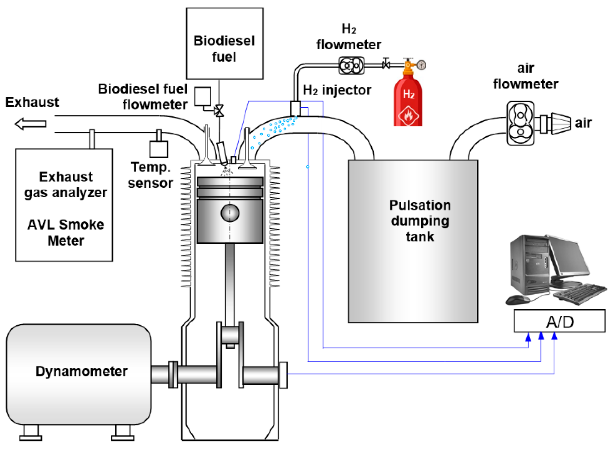
2.1. Research Engine and Apparatus

The paper presents the result of experimental research on the co-combustion of biodiesel (B100) with hydrogen in a compression-ignition IC engine. The tests were carried out on an industrial, single-cylinder, air-cooled, two valve engine. The engine worked at a constant speed of 1500 rpm. The research engine was equipped with additional fuel supply systems. Hydrogen was added using a Servojet SP051S1 gas injector controlled by a control system ensuring precise control of opening time. Biodiesel was injected directly into the engine’s combustion chamber. The injection timing was not changed. The engine worked with a constant load which was defined by indicated mean effective pressure (IMEP) with value of IMEP = 0.7 MPa. On-line indication was carried out. On the basis of this process was determined power, torque, rotational speed, indication mean effective pressure and was observed pressure traces. In addition, the test stand is equipped with a measuring system with a dynamometer. A diagram of a test stand equipped with an engine is shown in Figure 1. The test engine was also equipped with an indication system, a measurement system for gaseous fuel and air consumption. The system for measuring pressure changes in the cylinder included a pressure sensor, load amplifier, encoder for crankshaft angular position and A/D system for recording measurement data.
Table 1 presents test engine data. Test engine is air cooled one cylinder engine with compression ratio equal to 17.
The study used the following measurement apparatus:
-
Pressure sensor Kistler 6061, range 0–25 MPa, linearity < ±0.5% FS,
-
Charge amplifier Kistler 511, range ±10…±999,000 pC for 10 V FS, error < ±3%, linearity < ±0.05% FS,
-
Data acquisition module, Measurement Computing USB-1608HS-16 bits resolution, sampling frequency 20 kHz with software [23],
-
Air rotor flowmeter Common CGR-01 G40 DN50, measuring range 0.65–65 m3/h, accuracy class 1,
-
H2 rotor flowmeter Common CGR-01 G10 DN50, measuring range 0.25–25 m3/h, accuracy class 1,
-
Exhaust gas analyzer: THC, CO, CO2, O2-Bosch BEA 350 (THC: range 0–9999 ppm vol. accuracy: 12 ppm vol.; NOx: range 0–5000 ppm accuracy: 10 ppm.; CO: range 0–10 %vol. accuracy: 0.06 %vol.; CO2: range 0–18 %vol. accuracy: 0.4 %vol.; O2: range 0–22 %vol. accuracy: 0.1 %vol.; λ: range 0.5–9.999 accuracy: 0.01),
-
AVL Smoke Meter: measurement range 0–10 FSN, detection limit: 0.002 FSN or 0.02 mg/m³, standard deviation 1σ ≤ ±(0.005 FSN + 3%).
Table 2 presents the main properties of used fuels, biodiesel and hydrogen. Biodiesel is characterized by a higher value of cetane number compared to diesel fuel, which promotes the self-ignition process in the engine cylinder. Biodiesel also has a low autoignition temperature relative to hydrogen. High hydrogen laminar flame speed will reduce the combustion time and should increase the efficiency of the engine. When using biodiesel and hydrogen, no petroleum fuels were use.

2.2. Methodology

During the research, part of biodiesel was replaced by hydrogen. To determine the maximum share of hydrogen delivered to the engine during the tests, the on-line observation of pressure curve, pressure increase rate, heat release rate and engine load in subsequent cycles was done. At the maximum hydrogen content, pre-ignition of hydrogen as well as pronounced knocking sound effects were observed during the tests. The tested engine managed to reach almost 40% of the energy share of hydrogen.
During the tests, 200 engine cycles were recorded, and each measuring point was repeated at least three times. Before each measurement, the engine worked for several minutes to achieve thermal stabilization. Emissions of toxic exhaust gas components and soot were also recorded for each measuring point.
Table 3 presents the energy shares of biodiesel and hydrogen for the analyzed cases. Because of the assumption of a constant load for the engine, the decrease in the biodiesel share was accompanied with an increase in the hydrogen share to achieve that assumption. Such shares as presented in Table 3 resulted from measurements of biodiesel and hydrogen consumption and then were converted into energy shares. As it results from the data contained in Table 3 for tested engine, along with the increase of the hydrogen share in the fuel supplied to the engine, its energy demand decreases. Because of the hydrogen properties it should result in increase in engine thermal efficiency. The procedure for determining engine parameters and combustion stability evaluation is presented in the paper [4].
The indicated pressure is evaluated based on the recorded changes in the cylinder pressure and represents one of the indices that characterize operation of combustion engines in terms of the opportunities to ensure high and expected functional performance. Indicated mean effective pressure for a single engine cycle:
IMEP i = 1 V d 0 720 pdV
where p is in-cylinder pressure, V is cylinder volume, Vd is displaced cylinder volume.
Indicated mean effective pressure:
IMEP = i = 1 i = 200 IMEP i 200
where “i” is number of engine cycles.
The thermal efficiency of the test engine:
TE = IMEP   V d Q B 100 + Q H 2 100 %
where IMEP is indicated mean effective pressure, Vd is displaced cylinder volume, QB100 is the heat in biodiesel supplied to the cylinder and QH2 is the heat in hydrogen supplied to the intake manifold.
Heat release rate (HRR) was calculated from the measured in-cylinder pressure data and crank angle readings. The basis of determining the heat release rate was the first law of thermodynamics and the equation of state. After rearranging and simplifications, the heat release rate vs. crank angle is obtained in well-known form as follows:
HRR = 1 γ 1 [ γ p dV d φ + V dp d φ ]
where γ is the ratio of specific heats, V is cylinder volume, p is cylinder pressure. Instantaneous cylinder volume V determined on the basis of the engine geometry.
Due to omitting as follows: heat transfer to walls, crevice volume, blow-by and the fuel injection effect, the resulted heat release rate is termed as the net heat release rate. The cumulative net heat released was obtained by integrating of heat release rate over the crank angle φ.
The unrepeatability of IMEP of the test engine:
COV IMEP = STD IMEP IMEP   100 %
where STDIMEP is the standard deviation in indicated mean effective pressure.
Experimental measurements of physical properties are typically connected with a measurement error and measurement uncertainty.
The value of the uncertainty of determination of thermal efficiency is affected by the uncertainty of determination of indicated pressure, rotational speed, biodiesel consumption time in the engine cylinder and jet of hydrogen volume supplied to the intake manifold. Uncertainty of determination of indicated efficiency was determined based on three measurements of engine speed, time of biodiesel consumption in the engine cylinder and jet of hydrogen volume supplied to the intake manifold and three mean values of indicated pressure. Uncertainty of indicated efficiency was calculated from the formula:
Δ TE = (   TE   IMEP Δ IMEP ) 2 + (   TE   n Δ n ) 2 + ( TE t Δ t ) 2 + ( TE V in Δ V in ) 2
where ∆IMEP is the uncertainty designation of the indicated mean of effective pressure, ∆n is the uncertainty of the engine speed, ∆t is the uncertainty of the consumption time of biodiesel in the engine cylinder, ∆Vin is the uncertainty of hydrogen jet supplied to the intake manifold [24].
The uncertainty designation of the indicated mean of effective pressure, determine the dispersion (spread) around the average value calculation results of the IMEP in the individual cycles of the three measurements containing 200 recorded engine cycles. It was assumed that the uncertainty designation of the IMEP has a normal distribution and it is calculated from the equation:
Δ IMEP = t s   STD IMEP
where ts is coefficient of the t-Student distribution for N − 1 degrees of freedom and for the most commonly adopted technique in the 95% confidence level, STDIMEP is standard deviation of the IMEP.
The unrepeatability of IMEP of the test engine:
COV IMEP = STD IMEP IMEP   100 %
where STDIMEP is the standard deviation in indicated mean effective pressure.
It was adopted that uncertainty of determination of the unrepeatability of IMEP shows normal distribution and it was calculated from the following formula:
Δ COV IMEP = t s   STD COVIMEP
where STDCOVIMEP is the standard deviation of the coefficient COVIMEP.
Standard deviation for the coefficient of variation of the indicated pressure (STDCOVIMEP) is composed of the uncertainty of determination of standard deviation of the indicated work (STDIMEP) and uncertainty of determination of indicated mean effective pressure (IMEP). Standard deviation of COVIMEP (STDCOVIMEP) was calculated using the formula for variance of the function of two variables:
STD COVIMEP 2 = (   COV IMEP   STD IMEP ) 2 STD STDIMEP 2 + (   COV IMEP   IMEP ) 2 STD IMEP 2
where STDSTDIMEP is standard deviation of the standard IMEP deviation, STDIMEP is standard deviation of the IMEP.

3. Results

The impact of hydrogen addition for engine parameters was determined based on the pressure curve analysis. For each operating point, the pressure curve for 200 engine cycles was recorded, and the combustion process was assessed on the basis of the average course from the set. The analysis of the influence of hydrogen on the course of combustion pressure and pressure rise rate, as well as on heat release rate was done. The normalized heat release rate was then used to determine the characteristic combustion phases.
Figure 2 presents pressure curve for the analyzed hydrogen energetic shares. Along with the increase in the energetic share of hydrogen, an increase in the maximum pressure was observed, which was achieved closer to the top dead center (TDC). For the hydrogen energetic share of 38%, the pressure increased by 1.2 MPa compared to the pressure of the diesel engine. The pmax value was also 4 deg of crank angle (CA) earlier than a conventional engine. For the high value of energetic share for hydrogen, the start of combustion took place very early and the combustion process, as can be seen on pressure increase rate curve, occurred in two stages. It should also be noted that for all H2 shares, the peak values dp/dφ were within the allowable range for piston engines, i.e., below 1 MPa/deg.
Figure 3 presents heat release rate for an engine combusting biodiesel and hydrogen. The analysis of heat release in the engine is a reliable source of information about the combustion process. From the heat release rate (HRR) curves, it was found that with the increase of H2 energy share, the diffusion combustion phase decreases and kinetic combustion phase increase at the same time. It can even be stated that with an increase in the proportion of hydrogen in the place of the diffusion phase, an intermediate combustion phase appears between the kinetic and diffusion phases, which is shown by an additional local maximum on the HRR curve. For a 38% hydrogen share, the second peak on the HRR curve is even higher than the first peak of kinetic combustion which is typical for an engine. With a high proportion of H2, biodiesel combustion has two visible stages.
On the basis of the normalized heat release rate curves, the combustion stages were determined, i.e., the ignition delay time and the duration of combustion. In the field of IC engines, these times are defined in CA degrees, which allows comparison of results for different engines. Both physical and chemical processes affect the ignition delay time. The first processes depend primarily on the quality of fuel atomization, the method of its delivery to the combustion chamber and gas dynamics processes in the engine cylinder. These factors cause the so-called physical ignition delay. The second processes depend on the chemical properties and depend on the quality of the fuel, C/H ratio or the share of oxygen in the molecular structure, its heat of evaporation value, ignition temperature, laminar flame speed (LFS) or lower heating value (LHV). Both phenomena, i.e., physical and chemical delay, occur simultaneously. In practice, most often the ignition delay in a piston engine is assumed to be the period, expressed in degrees of CA, from the beginning of diesel injection until the release of 10% of heat. The next stage is the duration of combustion counted from the release of 10% of heat to the point of release 90% of heat.
In the combustible mixture hydrogen is premixed, it is ignited and combusted earlier than biodiesel, which can be seen from Figure 3 (the two-peaks). The combustion product of hydrogen is steam. The steam mixed with air and result in inhomogeneous to the biodiesel diffusion flame. This, among other things, affects the shape of pressure courses and its derivatives. These two peaks or trends related to heat release are associated with the combustion of fuels with different reactivity, as well.
Figure 4 shows the results of determining combustion stages. The first observation is the fact that the hydrogen content practically does not affect the ignition delay time in the engine. For the entire range of hydrogen share, ignition delay was constant. This was due to the high auto-ignition temperature of hydrogen and its participation in the mixture with air, despite the fact that it reduces the pressure of fresh charge before ignition, it does not affect the ignition delay. Another important stage of combustion is a time of 50% of mass fraction burn or 50% of heat release. This combustion stage is evaluated primarily in spark-ignition engines, where the combustion process is determined by the kinetic combustion phase. In the analyzed case, despite the fact that it is a compression-ignition engine, as already mentioned the addition of hydrogen moves the combustion system towards the isochoric process and this brings the engine closer in this respect to the spark-ignition one. The results obtained are particularly important for large hydrogen proportions, where the diffusion combustion phase is minimized. In the studied case, along with the increase in the H2 share, the value of the 50% heat release angle approached TDC. According to the literature, the engine reaches its highest efficiency as 50% of heat is released about 7–10 deg after TDC. In the analyzed cases, for the engine powered by B100 50% of Qnorm there was 14.5 deg after TDC and for the engine powered with 38% hydrogen share it was only 5.5 deg after TDC. Analyzing the duration of combustion, it was found that with increasing hydrogen content in the combustion process, the duration of combustion decreases. With 38% hydrogen, the duration of combustion decreased from 69.2 deg for biodiesel to 55.7 deg. Shortening the combustion time has affect in reducing heat losses to the engine cylinder walls. This effect has been confirmed by increase in engine efficiency with the participation of hydrogen in the combustion process.
Figure 5 shows the results of thermal efficiency for a biodiesel-hydrogen engine. It was found that for all analyzed hydrogen shares a higher thermal efficiency of the engine was obtained compared to the engine powered with biodiesel. The highest efficiency value was obtained for a 21% hydrogen powered engine and it was 41%, which was 7% more than for a biodiesel engine. For the highest share of hydrogen, a slight decrease in efficiency was noted, which may be caused by too early ignition of fuels, which can be clearly seen in Figure 2. For this energetic share of hydrogen, a 50% of the heat released is already too close to TDC, which does not favor the conditions for obtaining the highest efficiency of the engine [25]. Figure 5 shows the uncertainty intervals for determining the thermal efficiency, as well.
In the IC engine, the cycle-by-cycle variation of engine work cycles is an important problem. Analyzing the repeatability of engine cycles, the stability of the combustion process in the engine can be determined. The unrepeatability of IMEP (COVIMEP) was used as a parameter to determine the cycle-by-cycle variations. The COVIMEP is directly related to the investigated combustion stability. The COVIMEP was calculated based on set of IMEP values from 200 following work cycles of the test engine. The results of the analysis are shown in Figure 6.
The analysis of the repeatability of IMEP shows that for the majority of analyzed cases for hydrogen co-combusted with biodiesel, the COVIMEP value was within the acceptable range for industrial stationary engines. For industrial engines, COVIMEP below 5% is used as the limit value [25]. In the tests, the limit value was exceeded by 0.5% only once for the 11% hydrogen share. Figure 6b shows a different nature of changes and repeatability of normalized heat release. It can be stated here that the share of hydrogen does not significantly affect the start of combustion. Figure 6 shows the uncertainty intervals for determining of the unrepeatability of IMEP, as well. As shown in Figure 4, it does not change the ignition delay time. From the example at Qnorm curves it can be seen that with the increase of the hydrogen content, the instability in the developed combustion process phase increases. Combustion processes with a low heat release rate will be less favorable to NOx emissions but will be a source of soot emissions. A lower value of heat release rate cause also a lower combustion temperature. A high rate of heat release, accompanied by high temperature in the combustion chamber promote an increase in NOx emission and decrease in soot emission. By analyzing the repeatability of engine work cycles, the distribution of IMEP values was presented. The results are presented in Figure 7.
The presented distributions show that up to 5% of hydrogen, IMEP values are centered around the average value in a relatively narrow range. A similar relationship results from the COVIMEP analysis where for this range of H2 share the value of this parameter changed in the range of 1%. A significant increase in COVIMEP was observed for larger H2 shares. Analyzing the histograms of the IMEP distribution it can be said that with increase in hydrogen energetic share an equalization of distribution occurs with less visible dominant value of IMEP. This was due to prolonged combustion cycles that have low IMEP values.
Exhaust emissions including soot emissions were measured in a biodiesel and hydrogen engine tests. For industrial engines such as those used in the tests, exhaust emissions are reported in relation to kWh.
The obtained results show that in the tested engine, the increase in the energy share of hydrogen was followed by an increase in specific emission of total hydrocarbons (THC). Although the addition of hydrogen improves the quality of combustion of biodiesel hydrocarbons, the increase in THC emissions may be due to the increasing cycle-by-cycle variation in which the oxidation process may not take place completely. The highest increase in THC emissions was for 38% of H2 and was higher than obtained by combustion of biodiesel by 26%. Larger differences in emissions were recorded for NOx. Along with the increase in the H2 share, nitrogen oxide emissions increased in the whole range. The similar nature of the influence of hydrogen on the emission of nitrogen oxides is confirmed by literature data [26,27]. For the combustion of pure biodiesel, the specific emission of NOx was 3.92 g/kWh and for the 38% hydrogen share it increased to 10.4 g/kWh, i.e., there was an increase of over 2.5 times. A way to reduce nitrogen oxide emissions, as the literature results show, is to use exhaust gas recirculation [19].
Regarding CO and CO2 emissions, according to the assumptions, their emission decreased with an increase in the share of H2, because the hydrocarbon fuel was replaced by a fuel without carbon in its structure. This fact is reflected in CO2 emissions. The decreasing CO emission is also the effect of the described phenomenon but also because the hydrogen accelerates the combustion process, increases the phase of kinetic combustion and thus creates better conditions for complete and total combustion. The share of 38% hydrogen caused a more than 2.4-times decrease in specific CO emissions.
Soot emission is a very important factor in allowing a compression ignition engine to be used. The combustion chamber of the compression-ignition engine has very rich and very lean fuel zones. Fuel-rich zones are responsible for soot emissions. Lack of oxygen promotes the formation of solid particles. The mechanism of soot formation is very complex, and the impact on the formation of soot particles have both chemical and physical processes. The temperature of 1873 °C is a certain temperature limit for soot formation, below this temperature the soot formation process is intense, but above this temperature oxidation processes begin to dominate [25].
Figure 9 contains soot emissions for the range of hydrogen share in the combusted mixture. The first observation is that the engine fueled by biodiesel has a very high soot emissions compared to engine where biodiesel was co-combusted with hydrogen. Soot emission measurement was also carried out at identical settings for diesel fuel and soot emissions were more than two times lower. For soot emissions, the hydrogen addition is very beneficial because its 2% energy content has reduced soot concentration by over two times. With 38% hydrogen content, soot emissions were only 70 mg/m3. Figure 8 and Figure 9 show the error ranges for measuring the exhaust components. These errors resulted from the measurement accuracy of the exhaust gas analyzers used, which were presented in Chapter 2.
Summing up the analysis of exhaust gas emission components of the compression ignition engine, it should be emphasized that the tests were carried out at a constant injection angle of liquid fuel. The test engine was not equipped with any after-treatment system. For normal engine operation, the hydrogen content should not be greater than 10% due to high pressure increases and the risk of knocking. The problem which still remains and must be solved is the effective way of hydrogen production, storage and transport.

4. Conclusions

The paper presents the results of the assessment of the combustion process, combustion stability and exhaust emissions in a dual-fuel diesel engine fueled with biodiesel and hydrogen. During the research the part of biodiesel was replaced with hydrogen up to 38% of its energetic share to obtain constant load of the engine. The engine was powered by hydrogen through the electronic fuel injection system to the intake manifold and biodiesel was injected directly into the combustion chamber. Based on the results obtained, the following conclusions were drawn regarding the evaluation of the combustion process:
An increase in the share of hydrogen causes an increase in the maximum combustion pressure value;
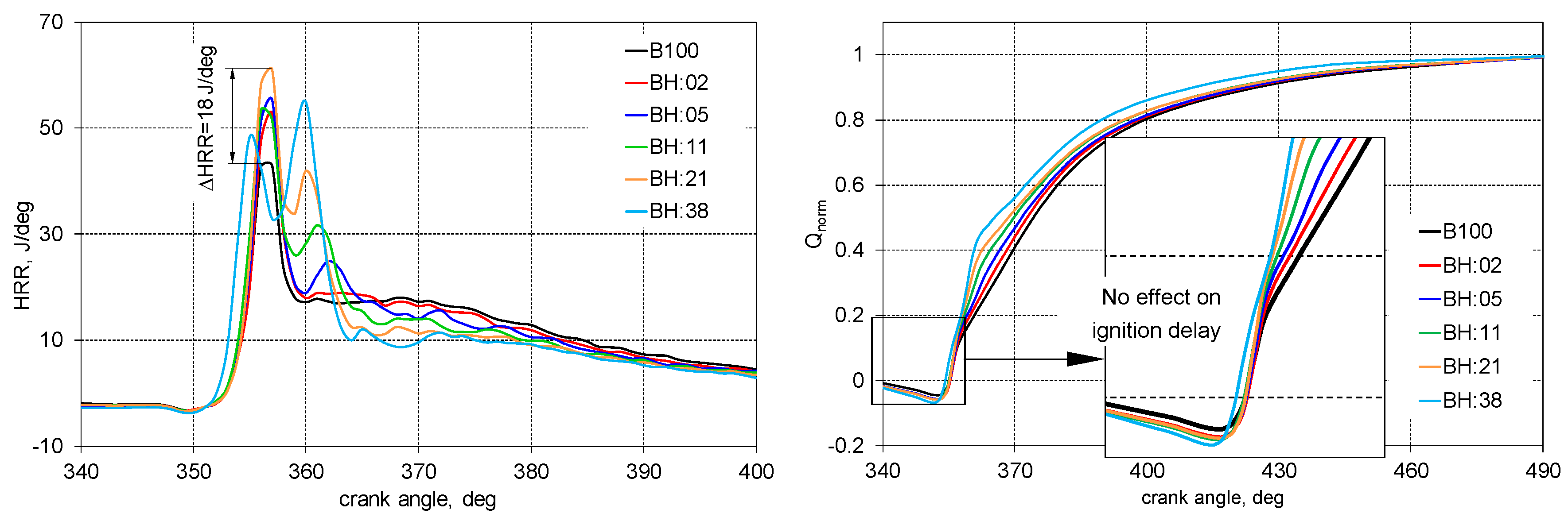
Increase in H2 energetic share cause a reduction in the diffusion combustion phase in favor of an increase in the kinetic phase;
For the 38% hydrogen share, the second peak on the HRR curve was higher than the first peak of combustion which is typical for engines;
The addition of hydrogen moves the combustion process closer to the isochoric one and this brings the engine closer to the spark ignition engine combustion;
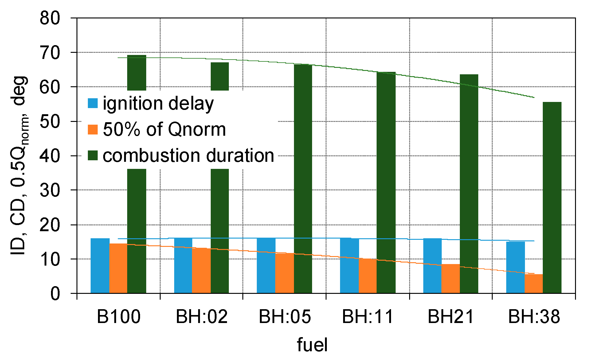
The share of hydrogen practically did not affect the engine ignition delay time, while the duration of combustion decreases. With 38% hydrogen, the duration of combustion decreased by 25% compared to the biodiesel engine;
The addition of hydrogen improving the thermal efficiency of the engine, the maximum value was obtained for a 21% hydrogen share;
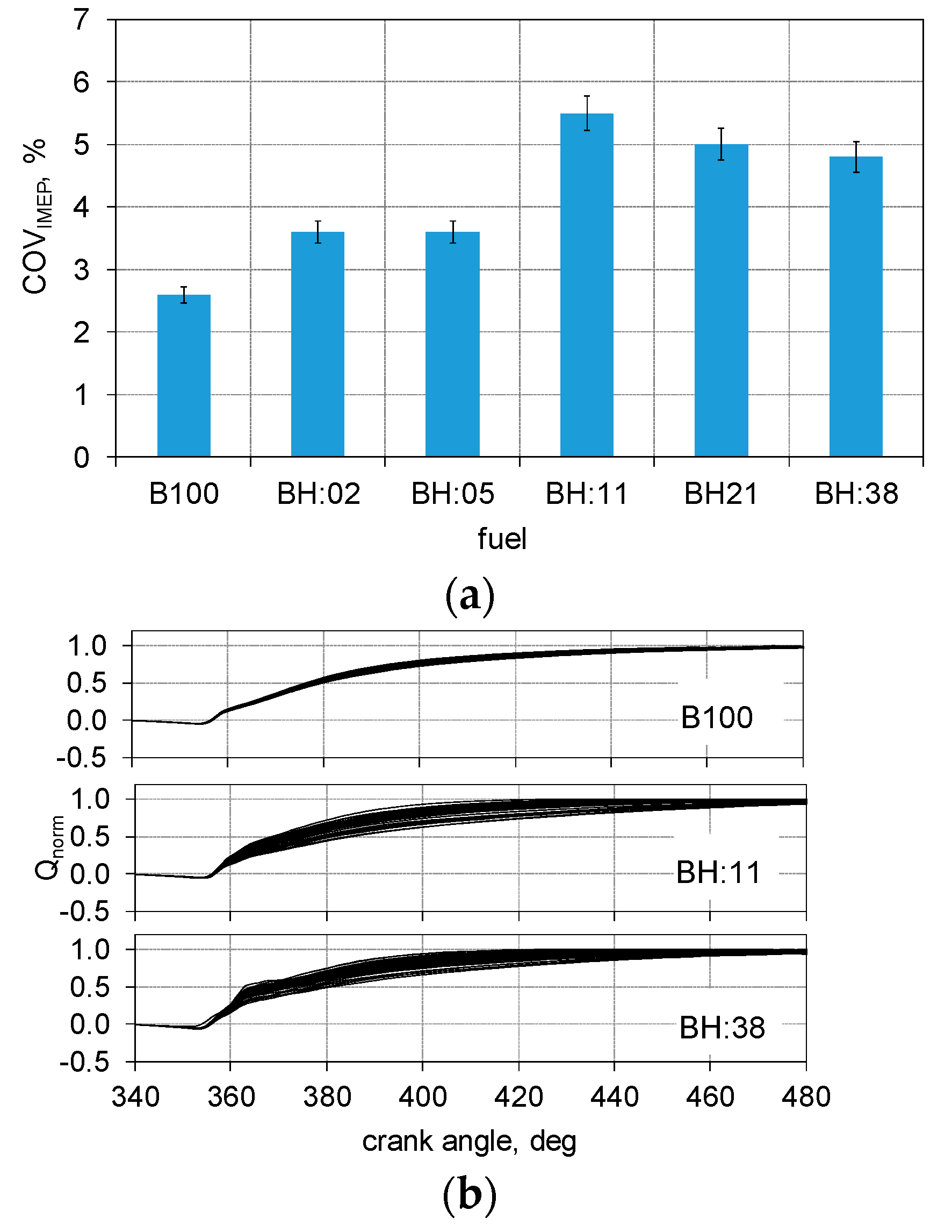
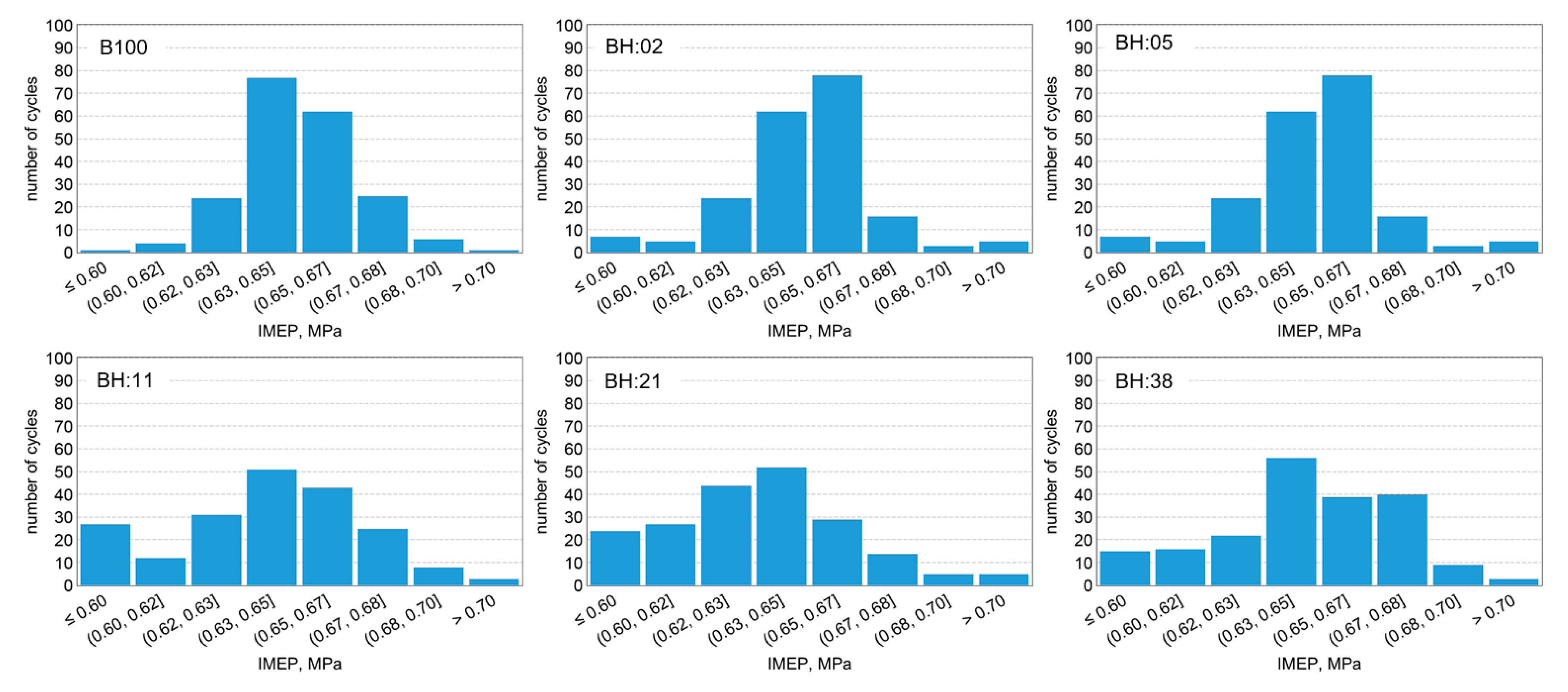
Instability of biodiesel and hydrogen fueled engine operation is within the allowable range for industrial engines (COVIMEP < 5%).
Conclusion regarding exhaust emissions:
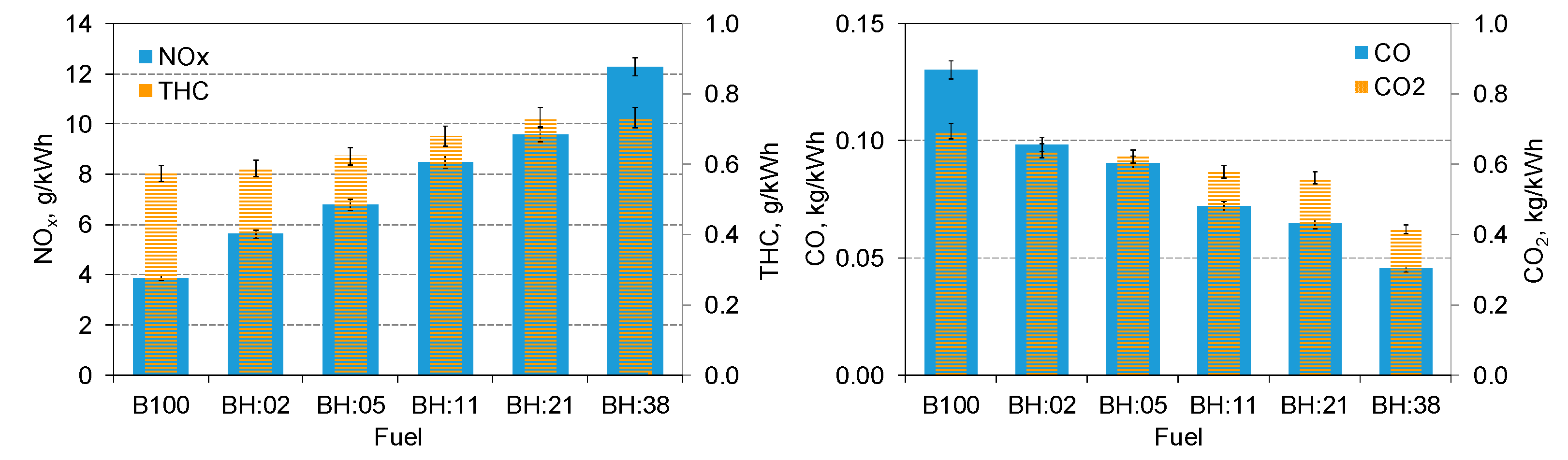
With the increase of hydrogen energy share, there was an increase in specific THC emission. The highest increase in THC emissions was for 38% H2 and it was higher than that obtained for biodiesel fueled engine by 26%;
H2 contributed to an increase in nitrogen oxide emissions in the entire range of its share, for 38% hydrogen share an increase in specific NOx emission of over 2.5 times was noted;
The share of hydrogen caused a decrease in CO and CO2 emissions, which is normal, for a 38% share of hydrogen there was a 2.4 times decrease in specific CO emissions;
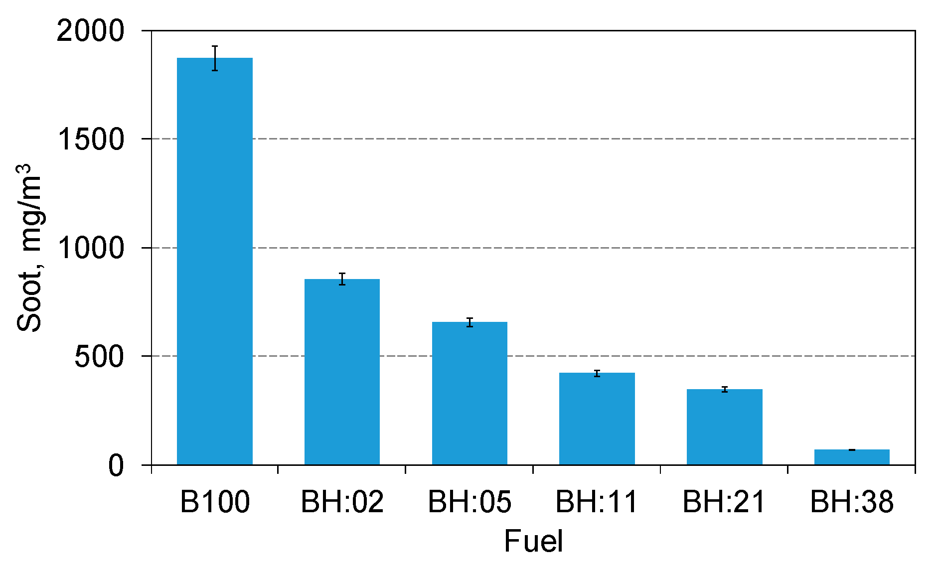
The share of hydrogen has a very beneficial effect on soot emission because its 2% energy share has caused a reduction of its emission by over two times. With 38% hydrogen content, soot emission was only 70 mg/m3 and was over 25 times lower than when biodiesel was combusted.
The research shows that co-combustion of biodiesel with hydrogen gives great benefits both in terms of improving the engine’s operational parameters as, e.g., an increase in engine efficiency and also has a positive effect on the emission of certain exhaust gas components and very significantly reduces soot emissions. For normal engine operation, the hydrogen content should not be greater than 10% due to high pressure increases and the risk of knocking.

Author Contributions

Conceptualization, W.T., A.J. and K.G.-R.; data curation, W.T., A.J. and K.G.-R.; formal analysis, W.T.; investigation, W.T., A.J. and K.G.-R.; methodology, W.T. and A.J.; writing—original draft, W.T.; writing—review and editing, W.T. and K.G.-R. All authors have read and agreed to the published version of the manuscript.

Funding

This research was funded by the Ministry of Science and Higher Education of Poland from the funds dedicated to scientific research No. BS/PB 1-100-3010/2019/P.

Conflicts of Interest

The authors declare no conflicts of interest.

References

  1. Merkisz, J.; Fuć, P.; Lijewski, P.; Pielecha, J. Actual Emissions from Urban Buses Powered with Diesel and Gas Engines. Transp. Res. Procedia 2016, 14, 3070–3078. [Google Scholar] [CrossRef] [Green Version]
  2. Zöldy, M.; Török, Á. Road transport liquid fuel today and tomorrow: Literature overview. Period. Polytech. Transp. Eng. 2015, 43, 172–176. [Google Scholar] [CrossRef]
  3. Tutak, W.; Jamrozik, A.; Bereczky, Á.; Lukács, K. Effects of injection timing of diesel fuel on performance and emission of dual fuel diesel engine powered by diesel/E85 fuels. Transprt 2018, 33, 633–646. [Google Scholar] [CrossRef]
  4. Jamrozik, A.; Tutak, W.; Grab-Rogaliński, K. An experimental study on the performance and emission of the diesel/CNG dual-fuel combustion mode in a stationary CI engine. Energies 2019, 12, 3857. [Google Scholar] [CrossRef] [Green Version]
  5. Jamrozik, A.; Tutak, W.; Gnatowska, R.; Nowak, Ł. Comparative analysis of the combustion stability of diesel-methanol and diesel-ethanol in a dual fuel engine. Energies 2019, 12, 971. [Google Scholar] [CrossRef] [Green Version]
  6. Kuszewski, H. Experimental investigation of the autoignition properties of ethanol–biodiesel fuel blends. Fuel 2019, 235, 1301–1308. [Google Scholar] [CrossRef]
  7. Jamrozik, A.; Tutak, W.; Pyrc, M.; Sobiepański, M. Experimental investigations on combustion, performance and emission characteristics of stationary CI engine fuelled with diesel-methanol and biodiesel-methanol blends. Environ. Prog. Sustain. Energy 2017, 36, 1151–1163. [Google Scholar] [CrossRef]
  8. Tutak, W.; Jamrozik, A.; Gnatowska, R. Combustion of different reactivity fuel mixture in a dual fuel engine. Therm. Sci. 2018, 22, 1191–1203. [Google Scholar] [CrossRef] [Green Version]
  9. Barik, D.; Murugan, S. Simultaneous reduction of NOx and smoke in a dual fuel DI diesel engine. Energy Convers. Manag. 2014, 84, 217–226. [Google Scholar] [CrossRef]
  10. Ma, Y.; Zhu, M.; Zhang, D. Effect of a homogeneous combustion catalyst on the characteristics of diesel soot emitted from a compression ignition engine. Appl. Energy 2014, 113, 751–757. [Google Scholar] [CrossRef]
  11. Adu-Mensah, D.; Mei, D.; Zuo, L.; Zhang, Q.; Wang, J. A review on partial hydrogenation of biodiesel and its influence on fuel properties. Fuel 2019, 251, 660–668. [Google Scholar] [CrossRef]
  12. Lilik, G.K.; Zhang, H.; Herreros, J.M.; Haworth, D.C.; Boehman, A.L. Hydrogen assisted diesel combustion. Int. J. Hydrog. Energy 2010, 35, 4382–4398. [Google Scholar] [CrossRef]
  13. Szwaja, S.; Grab-Rogaliński, K. Hydrogen combustion in a compression ignitron diesel engine. Int. J. Hydrog. Energy 2009, 34, 4413–4421. [Google Scholar] [CrossRef]
  14. Tuccar, G.; Uludamar, E. Emission and engine performance analysis of a diesel engine using hydrogen enriched pomegranate seed oil biodiesel. Int. J. Hydrog. Energy 2018, 43, 18014–18019. [Google Scholar] [CrossRef]
  15. Serin, H.; Yıldızhan, S. Hydrogen addition to tea seed oil biodiesel: Performance and emission characteristics. Int. J. Hydrog. Energy 2018, 43, 18020–18027. [Google Scholar] [CrossRef]
  16. Akar, M.A.; Kekilli, E.; Bas, O.; Yildizhan, S.; Serin, H.; Ozcanli, M. Hydrogen enriched waste oil biodiesel usage in compression ignition engine. Int. J. Hydrog. Energy 2018, 43, 18046–18052. [Google Scholar] [CrossRef]
  17. Rajasekar, E.; Selvi, S. Review of combustion characteristics of CI engines fueled with biodiesel. Renew. Sustain. Energy Rev. 2014, 35, 390–399. [Google Scholar] [CrossRef]
  18. Dimitriou, P.; Kumar, M.; Tsujimura, T.; Suzuki, Y. Combustion and emission characteristics of a hydrogen-diesel dual-fuel engine. Int. J. Hydrog. Energy 2018, 43, 13605–13617. [Google Scholar] [CrossRef]
  19. Dimitriou, P.; Tsujimura, T.; Suzuki, Y. Adopting biodiesel as an indirect way to reduce the NOx emission of a hydrogen fumigated dual-fuel engine. Fuel 2019, 244, 324–334. [Google Scholar] [CrossRef]
  20. An, H.; Yang, W.M.; Maghbouli, A.; Li, J.; Chou, S.K.; Chua, K.J.; Wang, J.X.; Li, L. Numerical investigation on the combustion and emission characteristics of a hydrogen assisted biodiesel combustion in a diesel engine. Fuel 2014, 120, 186–194. [Google Scholar] [CrossRef]
  21. Çalık, A. Determination of vibration characteristics of a compression ignition engine operated by hydrogen enriched diesel and biodiesel fuels. Fuel 2018, 230, 355–358. [Google Scholar] [CrossRef]
  22. Dimitriou, P.; Tsujimura, T. A fully renewable and efficient backup power system with a hydrogen-biodiesel-fueled IC engine. Energy Procedia 2019, 157, 1305–1319. [Google Scholar] [CrossRef]
  23. Gruca, M. Software for Acquisition of Internal Combustion Engine data. J. Kones 2004, 11, 205–211. [Google Scholar]
  24. Jamrozik, A.; Kociszewski, A.; Tutak, W. Indication errors of engine with two stage combustion system. J. Kones 2009, 16, 179–193. [Google Scholar]
  25. Heywood, J.B. Internal Combustion Engine Fundamentals; Mc Graw Hill: New York, NY, USA, 2018. [Google Scholar]
  26. Koten, H. Hydrogen effects on the diesel engine performance and emissions. Int. J. Hydrog. Energy 2018, 43, 10511–10519. [Google Scholar] [CrossRef]
  27. Castro, N.; Toledo, M.; Amador, G. An experimental investigation of the performance and emissions of a hydrogen-diesel dual fuel compression ignition internal combustion engine. Appl. Therm. Eng. 2019, 156, 660–667. [Google Scholar] [CrossRef]
Figure 1. Test stand.
Applsci 10 01082 g001
Figure 2. Combustion pressure curve and pressure rise rate for different energetic shares of hydrogen.
Applsci 10 01082 g002
Figure 3. Heat release rate and normalized heat release for different energetic shares of hydrogen.
Applsci 10 01082 g003
Figure 4. Combustion stages: ignition delay, time of 50% of heat release and combustion duration.
Applsci 10 01082 g004
Figure 5. Thermal efficiency of test engine.
Applsci 10 01082 g005
Figure 6. COVIMEP (a) and normalized heat released for B100, BH:11 and BH:38 (b).
Applsci 10 01082 g006
Figure 7. Distribution of indicated mean effective pressure (IMEP) for different energy shares of hydrogen.
Applsci 10 01082 g007
Figure 8. Specific emission of NOx, THC, CO and CO2.
Applsci 10 01082 g008
Figure 9. Soot emission.
Applsci 10 01082 g009
Table 1. Main engine parameters.
ParameterValue
Engine1CA90 Andoria
Type of engine Four stroke compression ignition
Number of cylinders1
Bore90 mm
Stroke90 mm
Displaced volume573 cm3
Number of valves2
Compression ratio17
Engine speed1500 rpm
Diesel injectionDirect injection
Hydrogen injectionPort injection
Diesel injection pressure21 MPa
Diesel injection timing343 deg
Table 2. Fuel specification.
ParameterBiodieselHydrogen
Molecular formulaCH3(CH2)nCOOH3H2
Cetane number565–10
Density at 1 atm and 15 °C (kg/m3)8550.085
Lower heating value (MJ/kg)37.1119.81
Heat of evaporation (kJ/kg)250-
Auto-ignition temperature (°C)>101585
Flame speed, m/s-2.65–3.25
Stoichiometric air-fuel ratio12.534.3
Viscosity at 40 °C (mPa·s)4.51-
Boiling point (°C)180–360−2529
Carbon content (%)850
Oxygen content, (%)10.80
Hydrogen content, (%)12.1100
Table 3. Energetic shares of biodiesel and hydrogen.
FuelB100BH:02BH:05BH:11BH:21BH:38
Biodiesel, J/cycle1102.21000.1896.8884.4763.4543.1
H2, J/cycle021.944.097.6205.3325.9
Energy, J/cycle11021022940.8882968.7869

