Review

A Systematic Literature Review of Various Control Techniques for Active Seat Suspension Systems

School of Engineering, RMIT University, Bundoora 3083, Australia
*
Author to whom correspondence should be addressed.
Appl. Sci. 2020, 10(3), 1148; https://doi.org/10.3390/app10031148
Submission received: 4 January 2020 / Revised: 31 January 2020 / Accepted: 4 February 2020 / Published: 8 February 2020

Abstract

:
Drivers of heavy trucks are exposed to large amounts of vibration which can lead to serious health risks. Many suspension systems/methods can be used to isolate these transmitted vibrations, such as vehicle suspension systems, cabin suspension systems and seating suspension systems. The central idea of the work is to identify the research gaps and raise our future research questions in this specific area. The novelty of this paper is proposing a model predictive controller for active vibration control of seating suspension systems. A systematic literature review of the existing work of the vibration control of seating suspension systems has been conducted. Various control techniques that are used in the seating suspension systems have been summarized and evaluated. This paper focusses on the biodynamic model of the driver and seat for the first step needed in the design of the seating suspension system. Then, it illustrates the different types of the system vibration controls and their performance evaluation methods. At the end, the paper details several active seating suspension systems including their actuation system structures and control algorithms which are used in the heavy vehicle trucks.

1. Introduction

Drivers of heavy trucks experience the whole body vibration (WBV) because they spend most hours driving for a long distance, which will result in discomfort of the diver [1]. Various elements can affect the ride comfort of the driver such as the road roughness, vehicle suspension system and seat suspension system [2]. In addition, the noise and vibration generated from internal combustion engines play a minor effect on the drivers’ discomfort as well [3]. As a result, human body subjected to the vibration can suffer from adverse health effects such as fatigue, back pain, motion sickness, nervous disorders, spline fracture [4].
Researchers in the field of WBV have classified the vibration assessment measures into three categories namely: the mechanical impedance, apparent mass and seat to head transmissibility [5,6,7]. These function categories are used to assess the human body subjected to the vibration. The mechanical impedance is defined as the periodic excitation force at a certain frequency divided by the resulting vibration velocity [8]. The apparent mass is expressed as the periodic excitation force at a certain frequency over the resulting vibration acceleration. The seat to head transmissibility is known as the response motion of the head divided by the response motion of the seat floor or seat base. The vibration acceleration data from experimental measurement is extensively used to analyze the WBV [9].
In the recent studies, various approaches were proposed to improve the ride comfort and avert the fatigue risks associated to the human body. Some researchers have improved the vehicle suspension system to reduce the input vibration into the human body [10,11,12], while others focus on enhancing the vehicle seat suspension design [13]. Similarly, few studies integrated both the vehicle suspension system and seat suspension system to isolate vibration transmitted to human body [14,15]. On the other hand, reducing the vibration transmitted through vehicle cabin suspension system was investigated [16]. In this paper, the main interest will be directed toward the seat suspension system and its control methods and implementations. The main contribution of this paper is in providing a systematic review about the active vibration control of seating suspension systems including their actuation system structures and control algorithms.
The advantage of the work is identification of the research gaps and clarification of the future research questions. The paper is organized as follows: Section 1 provides the overview about the biodynamic model of seat suspension system combined with human body. Section 2 presents the source of vibration that can transmitted to the human body. Section 3 shows the ride comfort evaluation methods. Section 4 addresses the type of suspension systems and analyses the importance of the integrated seat suspension with vehicle suspensions. Section 5 studies the actuator types used in the active seat suspension. Section 6 demonstrates the overview of the existing active seat suspension structure design. Section 7 evaluates the recent control methods applied in the active seat suspensions. Section 8 will identify research gap and research questions. Finally, Section 9 will conclude this review.

2. Biodynamic Model of the Human Body

To improve the ride comfort of the seated human being in a vehicle, the seating suspension system with seated human body must be modelled [17]. In the prevailing literature, most studies considered the mass on the seat as a rigid dummy mass which is assuredly incapable to provide accurate information about the dynamic behavior of human body parts under vibration road excitation [18]. Recently, several researchers have paid more attention to the development of a mathematical model of the human body as a biodynamic model, considering the seated human posture, rather than a rigid dummy mass to certify high precise system modelling [19,20]. Some of system models have been built using field experimental data results [21].
The biodynamic model can be divided into three classes: lumped models, finite element model and multibody human model. The lumped model is widely used since it considers the human body as spring and damper. It can be modelled as 1 degree of freedom (1 DOF), 2 DOF or 3 DOF. The finite element model is a powerful discretization technique which considers the human body as a model of finite degree of freedom where the human body model parameters are normally obtained experimentally through the human corpses [22,23]. The multibody human model is more complicated scheme than the lumped model since it considers the human body as a complex model whose properties result from connecting the rigid bodies through a pin and a socket joint [24]. In this review paper, all the representative research papers presented the seat and vehicle suspension system as a lumped system model consisting of mass, spring and damper because it provides simple mathematical equations in both time and frequency domain.
The lumped mass–spring–damper system model was used to represent the human body model. A seating suspension system model with the seated human body generally varies in terms of structure complexity represented by degree of freedom starting from 1 DOF into 15 DOF, which typically depends on the number of body lumped masses connected through the springs and dampers [25]. For simplicity, the majority of studies have considered the seat suspension system model with a seated driver body as 1 DOF as presented in Figure 1a, which is mainly composed of a single stiffness, mass and damper [26,27,28], while others have used 2 DOF to model the seat and human body suspension system as illustrated in Figure 1b. The 2 DOF system is widely used in the vibration field due to its simple structure and it can offer more information about the model dynamic parameters than the 1 DOF system [29]. Some studies have presented the human body system of neck, pelvis, head and torso as 4 DOF in addition to the 1 DOF seat structure as shown in Figure 1c. Therefore, the 4 DOF is the best representation of the seated human body among all the DOF models because it can provide the most accurate parameter estimation of the human body system model [30].

3. Type of Vibration

Vibration can be transmitted to the human body from the multi-axis directions as shown in Figure 2 where the vibrations are along the three longitudinal directions of x, y and z axes and along the three rotational axes of the roll, pitch and yaw. The vertical vibration in low frequency range especially from 3 to 10 Hz is the most severe vibration which affects the human comfort during driving [31]. Normally, the head and spine mostly resonate near 4 Hz, which is found to cause the high impact on the human body health [32], while the other vibration directions can slightly affect human comfort when driving the vehicle [33]. Hence, many methods are used to evaluate the WBV inside the vehicle, which will be presented in the next section.

4. Vibration Evaluation Metrics

4.1. The Weighted RMS Acceleration Value in ISO 2631-1: 1997

Various methods have been developed to evaluate the ride comfort of the passengers [34]. The most popular method is the ISO 2631-1: 1997 which is proposed by the international organization for standardization (ISO) [35]. This method is the most widely used to evaluate the WBV using the calculation of the weighted RMS acceleration as defined in Equation (1).
a r m s , w e i g h t e d = [ ( W ( ω )   a r m s   ( ω ) ) 2 ] 0.5 ,
where a r m s presents the RMS acceleration at the frequency ω , and W ( ω ) is the weighting factor which is plotted in a diagram stated in the ISO 2631:1997.
The value of a r m s , w e i g h t e d is compared with the level of comfort in the table which is specified in ISO 2631:1997. Table 1 presents the comfort level scales suggested by the ISO 2631standard.
On the other hand, ISO 8041-1:2017 is an international standard which is essentially used to assess the human response to vibration through the instrument vibration design. It principally specifies the performance specification for instrument designed to measure the vibration values. Vibration instruments specified in ISO 8041-1:2017 are intended to measure vibration for hand transmitted vibration, whole body vibration or low frequency whole body vibration [36]. The time averaged weighted acceleration value can be expressed mathematically as
a w = ( 1 T 0 T a w 2 ( δ )   d δ ) 1 2
where a w ( δ ) presents the translational or rotational frequency weighted vibration acceleration in a specified direction as a function of instantaneous time; a w ( δ ) is given in meters per second squared (m/s2) or radians per second squared (rad/s2).

4.2. VDV Value

The one fourth power vibration is another evaluation method that differs from the RMS acceleration since it is more sensitive to the road roughness and peak [37]. The one fourth power vibration is well known as Vibration Dose Value (VDV). It can be expressed mathematically by
V D V t o t a l = { 0 T [ a w ( t ) ] 4   d t } 1 4 ,
where a w is the frequency weighted acceleration, and VDV is the vibration dose value ( m s 1.75 ) and T is the total period of the day in seconds (s).

4.3. SEAT Value

Seat Effective Amplitude Transmissibility (SEAT) is also an evaluation method used to assess the seat comfort through the Power Spectral Density (PSD) [38]. It is used to reflect the performance of seating suspension as a predictor of the comfort of the seated occupant. Its mathematical representation is given by Equation (3)
S E A T = ( x ¨ w ) R M S ( x ¨ s w ) R M S ,
where x ¨ s w is the frequency weighted root mean square value of vehicle floor input acceleration; x ¨ w is the frequency weighted root mean square value of the seat output acceleration.

5. Type of Suspension Systems

There are three types of suspensions used to minimize undesirable vibration in the driver-seat structure system, namely, passive, semi-active, and active. However, some types of these suspensions fail to reduce the vibration under certain frequency ranges due to the high cost and excessive energy consumption [39]. All the above-mentioned suspension types can be operated by either hydraulic, pneumatic or electrical actuators. Passive suspension system is a conventional vibration isolator, which can attenuate the vibration only at a certain frequency range specifically in the high frequency range [40]. However, it fails to reduce the vibration at the low frequency domain practically from 1 to 10 Hz. It mainly consists of spring and shock absorber, which is well known as a damper. The spring stiffness and damping coefficient should be optimized properly to provide ride comfort in the high frequency range. An actuator can be added to the spring and damper to convert the passive suspension into an active suspension system, or a variable damper such as MR damper with a feedback control system can replace the conventional damper to form a semi-active suspension system.
Semi active suspensions comprise of a shock absorber that is essentially used to regulate and control the suspension damping by adjusting its parameters [41]. The required control force can be obtained according to the adjustable shock absorber position and its damping force. The MR and ER semi active suspensions are the most popular dampers being used recently because they work effectively to provide a quick response for energy dissipation level in the low-mid frequency range. However, a poor performance can be generated in the high frequency rang due to the specific dynamic range of the ER and MR fluid [42,43].
Active suspension system is an actuator-based system, which can reduce the seated human body vibration [44]. It is a computer-controlled suspension system that takes advantage from both mechanical and electronics aspects. Operationally, the sensors send the signals into the controller, which produces a control force signal fed into the active suspension system. The active suspension actuator then generates an opposite force that eliminates the spring deformation. In the active seat suspension, the actuators provide an energy which allows the seat to move vertically with respect to its base. It provides a good vibration attenuation regardless the road disturbances and noise variation. Figure 3 displays the type of suspension systems.

5.1. Multiple Degrees of Freedom Vibration

In the last few decades, most of the studies have paid more attention to suppressing the vibration that essentially comes from the vertical direction only [41]. However, the human body can be exposed to the vibration from different directions such as lateral and rotational directions. Undoubtedly, the effects of the vibration, which comes from all the other directions are not as severe as those from the vertical direction. Plenty of researches have been conducted on the 1 DOF active seating suspension system in the vertical vibration, whereas other researches have been focused on multiple DOF seating suspension system in multiple axis directions, for example, in the vertical and horizontal vibrations [46] or vertical and longitudinal vibrations [47]. Different types of actuators with various mechanism structures are normally adopted in these multiple DOF seating suspension systems.
Some multiple DOF active seating suspension systems have been reported. The force and stiffness control method was used to reduce the vertical and lateral vibration generated from the forest machinery [48]. The proposed seat was designed by El Shobaki as illustrated in Figure 4 where the seating suspension structure consists of four pneumatic cylinders. The four pneumatic cylinders can rotate around the lateral axes. The seating suspension structure provides a smoother movement and more reliable performance than the conventional design. The seat basically can be moved based on the opening valve of the cylinder for each pneumatic system, where the input of the servo valves is the control signal directed from the F-K controller.
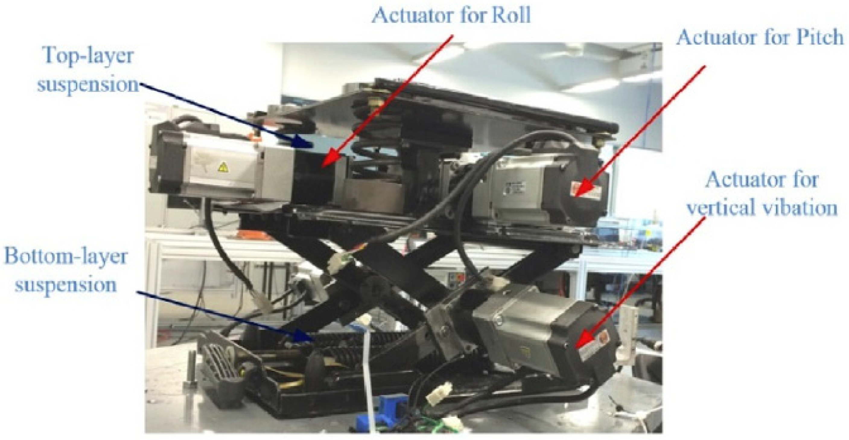
Another 2 DOF active seating suspension system was designed to eliminate the vibration in the vertical and roll axis directions [49]. The seating suspension structure system consists of two layers: The bottom layer was used to control the vertical vibration, and the top layer was primarily designed to reduce the roll vibration. Figure 5 shows the structure of the active seat suspension.
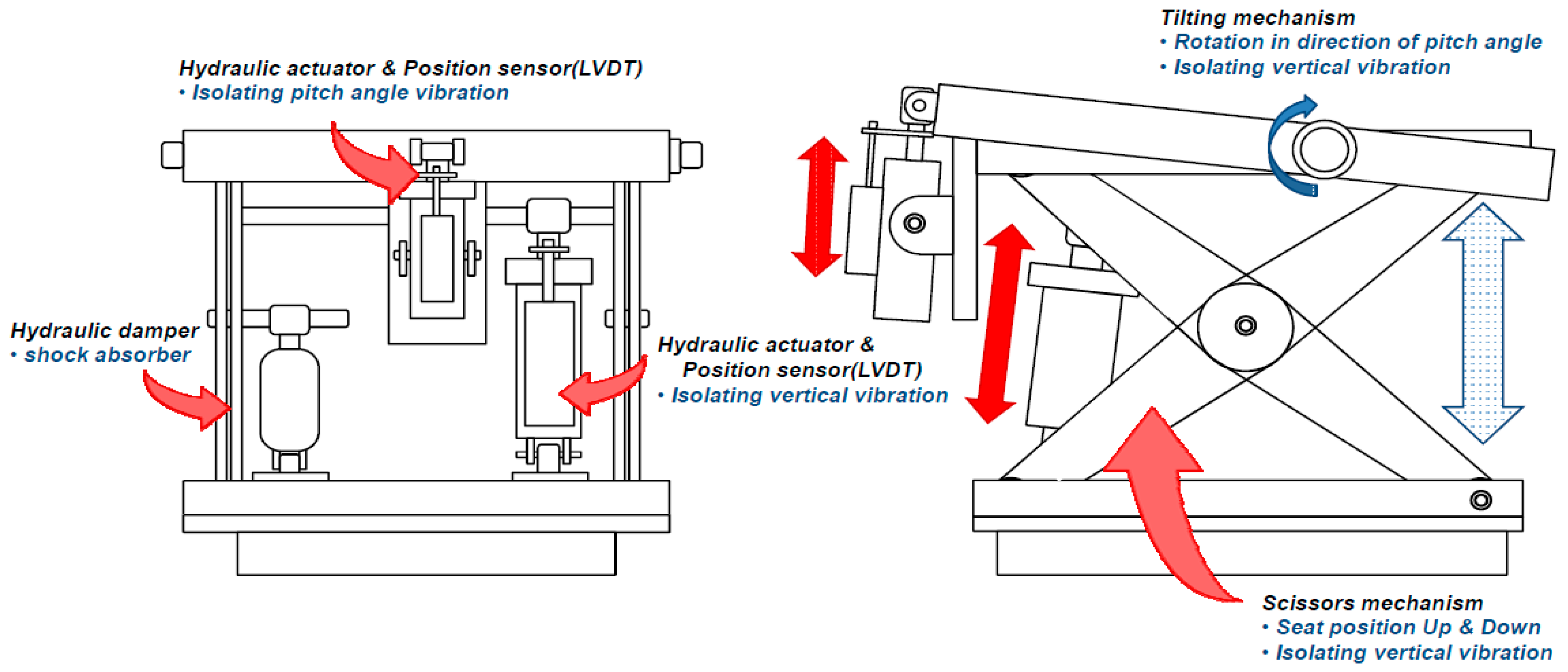
The seat suspension was designed for the military vehicle to reduce the effect of the vibration in the vertical and lateral directions as reported in [50]. A 2-DOF active seating suspension system was proposed to reduce the vibration in the vertical and pitch directions [51,52]. The scissor structure mechanism was adopted on the base frame to reduce the vibration in the vertical direction. The attached tilting platform on the top of the seating suspension was proposed to control the pitch motion [51]. The experimental test results showed that the active seating suspension system is stable in the low frequency range of 0–5 Hz.
Few recent studies have studied the effects of the WBV in the fore-aft and horizontal directions [53,54,55]. The worst frequency range which affects the human body in the horizontal direction is from 1–2 Hz [56]. These studies were carried out under three categories: vertical axis direction only (z), horizontal axis direction only (x) and combination of both the vertical and horizontal axis directions (z and x) with a driver mass variation from 60 kg to 90 kg. The results showed a minor impact on the backrest under low frequency range due to the cross coupling between the vertical and lateral axes [57]. Evidently, the majority of studies confirmed that the horizontal vibration is insignificant in influencing the WBV in many cases [58,59].

5.2. Integrated Active Seat Suspension with Vehicle Suspension

In the last few decades, the majority of studies have been developed to integrate the seat suspension with the vehicle suspension to provide high performance in the ride comfort since design strategies of control force can be implemented in both the seat and vehicle suspensions taking into the account the road disturbance that can be applied direct to the vehicle wheels rather than to the cabin floor [60,61]. Additionally, the seat suspension system normally integrated with the vehicle model can be evaluated for the seat performance considering different features such the tire deflection and suspension stroke [62]. There are three types of vehicle suspension model, namely: full, half and quarter vehicle suspension models. For the most recent studies, the quarter vehicle suspension model has been extensively used to examine the vertical vibration of the human body due to the simple mathematical model that includes all essential parameters. However, the quarter vehicle suspension model cannot provide a clear information about the pitch and roll motions like the half and full vehicle suspension models do. In [14,63], the researchers have integrated the active seat suspension with the quarter car suspension and considered a driver human body as a four degree of freedom (DOF). Robust H control method has been implemented with both the state and static feedback controllers [14]. The active seat suspension and the vehicle suspension have been controlled separately, and the results of the separate controls have been compared with those of the integrated seat and vehicle suspension system [63,64]. It was shown that integrated control system has better ride comfort performance than the separate control systems. However, it is difficult to implement the active suspension vehicle with the active seat suspension in the real application due to the high cost, control design algorithm complexity and vehicle energy consumption. Figure 6 shows the active quarter suspension model with active seat suspension system. Table 2 summarizes the current work in active seat suspension in multiple vibration directions.

6. Actuators Used in the Active Seat Suspension System

Certain types of actuators have been implemented to drive the active seat suspension in different directions. These actuators are divided into three categories, namely: hydraulic, pneumatic and servo actuators. Some moving machinery vehicles are driven by hydraulic power. Therefore, it is advantageous to adopt a hydraulic actuator for the active suspension system, while pneumatic and servo actuators are used for the other systems. The main problem related to the pneumatic actuators is that they need more energy to keep the enough air pressure in the source. Furthermore, they require much longer response time to the control signals due to the air compressibility. In addition, the mathematical model complexity of the system makes the pneumatic actuators less reliable and less convenient [65].
Air springs have been extensively used in the seat suspension and vehicle suspension systems of heavy trucks because the pressure inside the spring is changeable and would provide an extra comfort and ride quality [66,67]. Recently, it was found that the air spring has a significant advantage over the coil spring as the spring rate varies with the supplied air pressure and makes the seat suspension stiffness consistent and reliable.
Plenty of studies have used rotatory motors to drive the active seating suspension system in the vertical direction by varying the motor torque though a control signal. They have been shown to have sophisticated advantages over linear motors in terms of the low cost and low energy consumption. Additionally, the rotary motor can be integrated with a gear reducer to provide a required high torque to drive the active seating suspension system.

7. Active Seating Suspension System Structure Design

Various active seating suspension system structures have been implemented for vibration control. The most popular structure mechanism is the scissor structure which takes in a x shape. It was designed with air spring as shown in Figure 7 [68]. The bottom plate of the seat base was fixed to the cabin floor and the top plate was connected to the seat chassis. The air spring was placed inside the inner scissor structure while the shock absorber linked the top and bottom plates of the seat base.
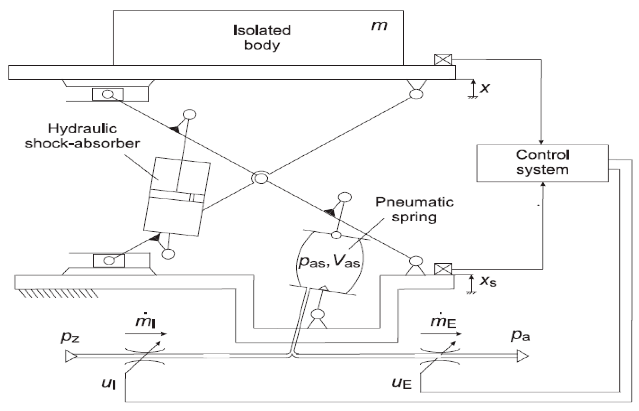
The seating suspension system structure shown in Figure 8 consists of a scissor structure mechanism, a hydraulic absorber and a pneumatic spring. The air flow inflates the air to the pneumatic spring through two valves that are controlled using a control signal. Hence, the air pressure is always changing inside the air spring generating an active force to drive the seat in the vertical direction [69].
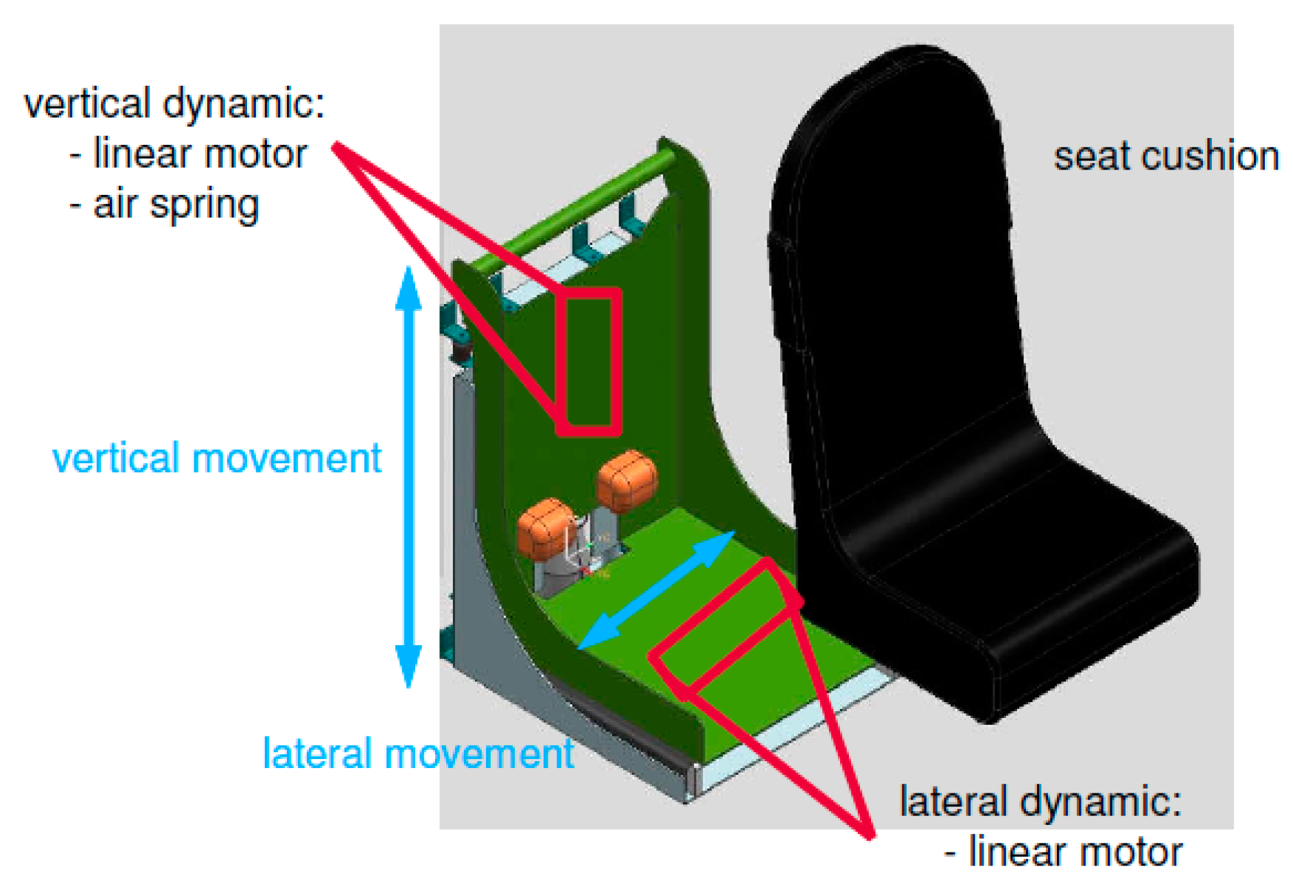
Another structure of the active seating suspension system proposed consists of two linear electric motors, which can slide independently along the vertical and lateral directions [50]. The vertical linear motor was placed in the backrest of the seat while the lateral linear motor was placed under the seating surface as illustrated in Figure 9. The air spring was implemented in the vertical direction to achieve the desired seat level.
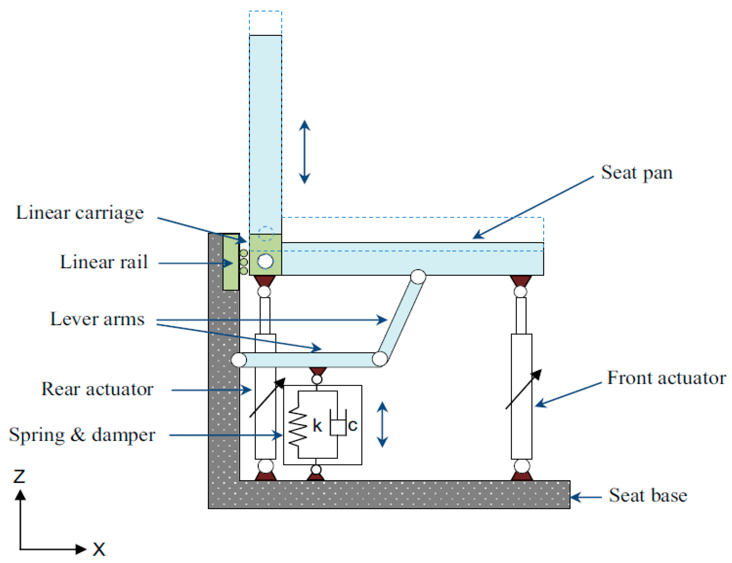
The seating suspension system consists of passive and active suspension systems [70]. The passive suspension system consisting of the coil spring and adjustable damper to support the driver body and seat pan. The active suspension system is composed of two parallel linear actuators to generate the active control force. Two bar lever mechanisms were used to support the seat pan. The seat can move vertically through the linear sliders placed at the seat rail as shown in Figure 10 [70].
The following seating suspension system structure consists of three active mounts and one vibration exciter where three accelerometers are used to measure the acceleration of the human body as illustrated in Figure 11 [71]. The seat was supported with three passive springs. At the middle of the seat base, the vibration exciter was placed to produce a displacement out as a real road profile.
A seating suspension system structure that is mainly used to eliminate the vibration in the vertical and pitch directions for an agriculture tractor was implemented in [51]. The active seating suspension system with a scissor structure mechanism was driven by a hydraulic actuator in the vertical direction. The hydraulic damper was used in parallel with the hydraulic actuator to absorb the shock during operation. Another actuator was attached to the upper frame with a tilting platform to control to the pitch motion as seen in the Figure 12.

8. Control Methods Used in the Active Seating Suspension System

In the last few decades, researchers have made considerable efforts in the seating suspension system control algorithms to achieve ride comfort and reduce vibration. The control algorithms and techniques of active seating suspension system have been improved from the conventional controllers such as PID controllers to a modern control system like Linear Quadratic Regulator (LGR), then to the smart and intelligent controller such as Fuzzy Logic Controller (FLC) and Artificial Neural Network (ANN) to an advanced control algorithm such as H infinite (H) and Sliding Mode Controllers (SMC). In addition, hybrid controller methods such as PID-FLC and SMC-PI have been designed by many researchers. Generally speaking, the main aim of the researches is to come up with a simple structure and robust performance controller to achieve the required design. In this section, several control strategies of the active seating suspension system will be discussed in detail.

8.1. Robust H Controller

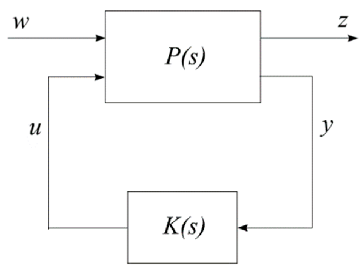
In the early 1980s, a new controller strategy was proposed by Zamas and Francis called H [72]. The H controller is an optimal control theory developed in the frequency domain which addresses the feedback design issues related to robustness [73]. It has been used extensively in many research fields and applications due to the mathematical optimization solutions and has a superior advantage over classical controllers. It is applicable to provide high stability performance of the plant in present of disturbances and noises. However, it requires a high level of mathematical understanding and large control efforts [74]. Figure 13 illustrates the standard H configuration where P(s) is the generalized plant; w is the external input; z is the output signal, which contains the performance and robustness measurements; u is the vector control signal; y is the plant output vector to the controller K. The main objective of the H is to find a feedback controller gain K to minimize the output z. Generally speaking, the controller gain K should minimize the H norm that is min T z w .
The mathematical model of the above closed loop system is represented as follows
[ z y ] = [ p 11 p 12 p 21 p 22 ] [ w u ]
Since z must be minimized, therefore, it can be written as
z = [ P 11 + P 12 K ( I P 22 K ) 1 P 21 ] w = l ( P , K ) w ,
where l ( P , K ) w is the lower linear fractional transformation of P and K. The design objective becomes
K s t a b i l i z i n g m i n l ( P , K ) w
and is referred to as the H optimization problem.
H strategy has been intensively used in the active seating suspension system control [75]. In [76] the author used the static feedback H controller with friction compensation based on the seat acceleration, suspension relative displacement and suspension relative velocity. An acceleration measurement-based observer was designed to estimate the friction. The state feedback controller with friction estimation was built as
u = K X + f r ˜ ,
where K is the state feedback gain, and f r ˜ is the estimated friction.
The experiment was conducted under the sinusoidal excitation in the frequency range of 1–4.5 Hz, bump road excitation and random road excitation. The acceleration Power Spectral Density (PSD) and ISO 2631-1 were used to evaluate the seating suspension system comfort performance. The experimental results indicated that the seating suspension system comfort performance was improved from a little uncomfortable of 0.6267 m/s2 RMS acceleration to a not uncomfortable of 0.2615 m/s2 RMS acceleration.
H controller was used in the active vibration cancellation to reduce the vertical vibration of a vehicle seat and guarantee the stability [71]. The external disturbances were constructed as additive uncertainty and unmodelled dynamics. A hybrid structure consists of feedforward and feedback controller were designed to increase the robustness of the active seating suspension system. The active seating suspension system was tested under a random broadband excitation. The experimental results showed a vibration attenuation in the real time control by 3.3 dB. However, the active seating suspension system comfort performance became degraded when the random excitation was applied.
Plant uncertainty such as actuator saturation, suspension deflection and tire deflection were considered when designing a novel optimal approach of the active seating suspension system based on output feedback H controller [77]. The Linear Matrix Inequality (LMI) was applied to obtain the desired controller. The active vehicle and seat suspension model were mainly used to minimize the vertical acceleration of the driver to ensure the ride comfort. The seat and human model were considered in the vehicle model. Three types of road profiles were applied to excite the active vehicle and seat suspension system namely: bump road profile, type C road profile and combination of the bump and type C road profile. The simulation results showed that the proposed controller can provide a good vibration attenuation under the road disturbances. However, the effect of the non-linear factors and input delay were not included in the study.
Takagi–Sugeno fuzzy control based on a disturbance observer was applied to improve the ride comfort of the driver [45]. Disturbance observer was used to estimate all possible disturbances caused by model simplification, friction force and actuator saturation. The driver mass variation was estimated using T-S fuzzy control. The H feedback controller was designed based on the acceleration and suspension deflection which could be measured during the real application. The bump and random road profiles have used to validate the proposed controller with different driver masses of 55 kg and 70 kg. The RMS accelerations using the H feedback controller was significantly decreased by 45.5% when compared with those using a passive seat suspension under the bump road test and reduced by 49.5% under the random road profile. However, the driver mass was assumed to be known in the experiment. The estimation parameter algorithm of the real driver mass was not illustrated in the paper.
A robust H sampled data control based on input saturation is proposed in [78]. The passenger dynamic model and the seating suspension system model were considered in the active suspension system model to ensure a high precise dynamic model, which contains all uncertainties related to the system. The robust controller was designed to meet some criteria such that the body acceleration must be small to ensure a high level of ride comfort under road disturbances. The seat deflection must not exceed the maximum allowable stroke of the suspension to ensure the safety of the seat, and finally, the dynamic tire load must be smaller than the static load [79]. The proposed controller was validated through a practical design example.
A H controller for active seating suspension system within a chosen finite frequency range was reported in [80]. The chosen frequency was considered as 4 Hz at which the severest vibration is transmitted into the human body. The results in the entire low frequency range and in a finite frequency range were compared. A better performance of the proposed controller in a finite frequency range was guaranteed in terms of the disturbance attenuation.

8.2. Preview Controller

Preview controller is a type of controller that has been used to control the vehicle active suspension system [81,82]. It was proposed by Bender in 1968. It mainly depends on the road profile measurement of the wheels or vehicle suspension. There are two types of the preview control which are called the look ahead and the wheelbase. The look ahead preview control normally obtains the information from the vehicle ahead, and that information is fed to the front and rear wheels of the active suspension system. The wheelbase preview control collects the information from the front wheel dynamic characteristic variations and uses that information to control the rear wheel of the active suspension system [83].
Preview information control was used in the active seat suspension where the actuator active force was calculated from the vehicle suspension dynamic information rather than the road disturbances [84]. The controller gain was optimized by genetic algorithm (GA). The proposed control method was validated using simulation and experimental tests where the quarter car suspension model was implemented with 1 DOF seat suspension model. The experimental test was performed under the bump and random excitation road profile with different vehicle speed. It is shown that a significant acceleration reduction of 10 dB is achieved across the frequency range 0−18 Hz.
In addition, a preview information was obtained from the wheels, front left suspension and front axle, which was optimized by fuzzy logic controller to cope up with friction and actuator constraints [85]. State feedback of the seat suspension and feedforward of the vehicle suspension based on preview information were implemented in [86]. In general, the preview controller can guarantee a good performance in terms of vertical vibration attenuation. However, it is quite costly, as it consumes energy and takes longer time to preview the road as well as requires more sensors to predict the road condition [87].

8.3. Sliding Mode Controller

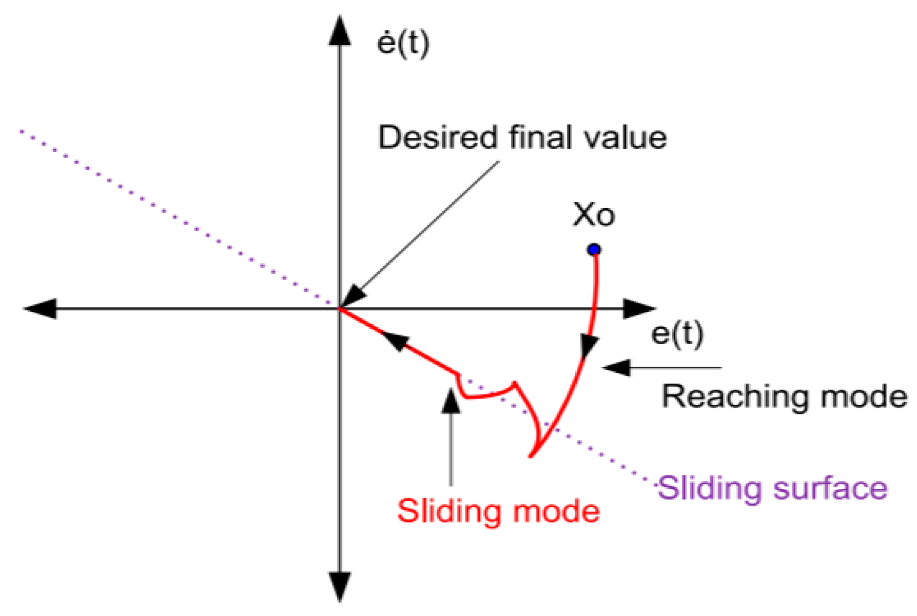
Siding mode control (SMC) or variable structure control (SVC) has been widely used in the control research field due to its robustness against external disturbances and system uncertainty [88]. It is completely insensitive to the parametric uncertainty during the sliding surface. The control strategy was proposed in the 1950s in the Soviet Union by a research group consisting of Emelyanov, Itkis and Utkins. The concept behind the slide mode control is to switch the state feedback control law from one continuous structure to another using high frequency switching control [89]. Hence, the system motion slides along a surface called sliding surface with certain boundaries called slide mode. Generally speaking, the feedback controller impulses the system to reach the sliding surface within a finite time and make it toggle between two phases either on and off or reverse and forward. When the system is finally at the sliding surface, the control input is sustained. Figure 14 shows the system trajectory with sliding surface. The main advantage of sliding mode controller is its robustness against the disturbances. However, the sliding mode controller has a drawback of chattering problems that is always associated with many design applications.
Sliding mode controller has been implemented in the active seat suspension in [91] where the author used a modified Terminal Side Mode Controller (TSMC). The TSMC has advantages over the conventional sliding mode controller in terms of the fast convergence time. The disturbance observer was designed to reduce the chattering by reducing the switching gain. The state observer was used to estimate the absolute velocity, and a complementary filter was implemented to fuse the data to ensure accurate estimation results.
The model simplification from a 6 DOF to 1 DOF active seat model was applied to design the TSMC with a remarkable consideration for disturbances generated from the simplified model. The active seat suspension performance was evaluated using the acceleration PSD and ISO 2631-1 under random vibration. The experimental results showed that the proposed controller has reduced RMS acceleration by 54.6% compared with the vibration reduction in a well-tune passive seat suspension.
In addition, a non-singular siding mode controller was implemented to reduce the roll vibration and lateral acceleration in the top layer of active seat suspension [49]. A SMC based disturbance observer (DO) is used to estimate the unmeasurable states [92]. The proposed controller was robust to the uncertainties generated from the suspension mechanisms, road profile disturbances and driver weight differences. A cascade control method was proposed for active seating system suspension where the SMC was implemented for force and stiffness tracking of the active seating suspension system, and a proportional valve controller was used to regulate the actuator pneumatic positions [48]. The Lyapunov’s method was used to evaluate the SMC stability. The experimental results showed a 20% reduction in the vibration acceleration amplitude of the active seating suspension system in the frequency range from 0.5 to 1 Hz.

8.4. Adaptive Controller

Apart from the above control methods which were discussed above. Several factors may influence the system stability and performances such as the mass variation of the driver, system modelling and nonlinearity of the plant. To cope up with these drawbacks, adaptive control methods were proposed. It has been most widely used in the recent control fields [93]. In the active control area, the adaptive controller is superior to the classical controller in terms of reducing the noise and suppressing the vibration practically if the ideal model reference is available. The adaptive controller method consists of three main parts: a plant which contains the system parameters, a reference model which represents the desired performance of the system and the adaptation mechanism which updates the system parameters instantly [94]. The key feature of the adaptive controller is to find the proper parameters which guarantee the system stability and ensure zero tracking error. Figure 15 represents the adaptive controller scheme.
Filtered-x least mean squares (FXLMS) algorithm is one of the adaptive control methods, which was proposed in 1963 [96]. It has been extensively used in reduction of noise and vibration due to its robustness and vibration attenuation capacity. FXLMS algorithm integrated with the on-line Fast-block LMS (FBLMS) identification process to suppress the vibration of the active seat suspension in the vertical direction under low frequency periodic excitation were reported in [70]. The effectiveness of the controller was examined through an experimental test with different road profiles. The results of the switching frequency test have validated the stability of the control.
In addition, the FXLMS algorithm was proposed to decrease the undesired vertical vibration of the vehicle seat in [71]. The FXLMS algorithm was combined with a robust controller to achieve good performance. The source frequency was set at 10 Hz, 20 Hz and 30 Hz. Therefore, the FXLMS was found to be able to attenuate the vibration at 20 Hz where the low frequency was considered in the range of 0–30 Hz. Additionally, the adaptive controller mechanism was proposed to compensate the seat suspension system in terms of the driver mass variation [69].

8.5. PID Controller

PID controller is a simple and reliable controller, which is commonly used in many industrial applications due to its flexibility [97]. The standard form of PID control can be represented as
u = k p   e ( t ) + k I   0 t e ( τ )   d ( τ ) + k d d e ( t ) d ( t ) ,
where u is the actuating control force, e is the error difference between the output and input defined as e(t) = y(t) − x(t). k p , k I and k d are proportional, integral and derivative control parameters of the controller.
PID controller was used to reduce the vertical and pitch accelerations for active seat suspension associated with the state variable feedback controller for precise displacement and velocity control through the actuator [51]. The state feedback was proposed to eliminate the overshot caused by the actuator with a PID controller. Generally, PID is integrated with various control methods either to reduce the overshot of the plant or to speed up the control system.

8.6. Adaptive Neuro Fuzzy Interference System

Adaptive Neuro Fuzzy Interference System (ANFIS) is a type of artificial intelligence controller that combined the features of both the fuzzy logic theory and neural network methodology. The fuzzy logic theory provides effective solutions to the information from the collected data while neural network methodology uses the learning capability of the method to improve the solutions. Therefore, the fuzzy membership functions and fuzzy rules can be adjusted adaptively through the NN learning process [98].
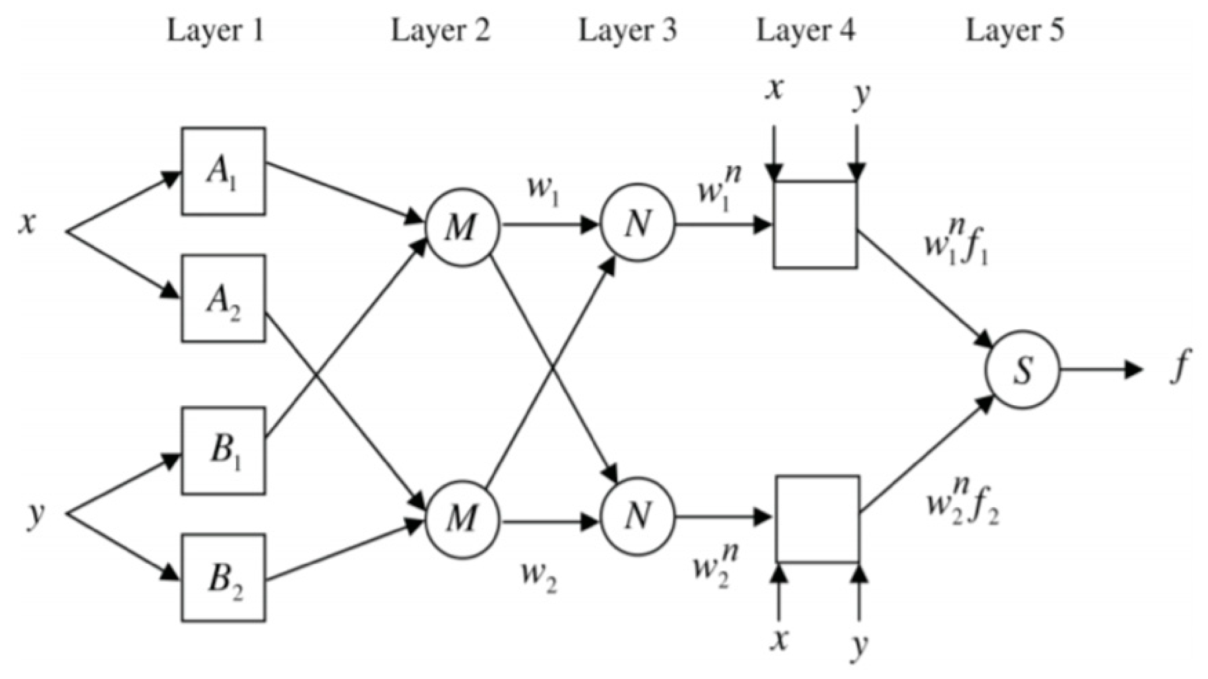
ANFIS consists of 5 layers as illustrated in Figure 16. Layer 1 receives two crisp inputs namely error e and change of the error d e to perform the fuzzification process. The node of the layer one is an adaptive node. Layer 2 contains the rule layer and its node is a fixed node which provides the output of cross multiplication of the input signals. Layer 3 is a fixed node with normalization layer. Layer 4 is an adaptive layer which generates the defuzzification layer. It takes the e and d e as an input associated with layer 3 output. Layer 5 is a fixed node which generates the ANFIS controller output. The ANFIS has the numerical and linguistic knowledge, which make it an advantage for many researchers.
ANFIS has been used in the active vehicle suspension system to enhance the ride comfort of the driver [99,100,101,102]. It was proposed to actively control the seat suspension system [64]. It was implemented under three different cases: the active quarter main vehicle suspension, active seat suspension and the active control system integrated within both the vehicle and passenger seat suspensions. The ride comfort was evaluated using the weighted RMS acceleration and VDV. The simulation result has indicated that the active control system integrated within both the vehicle and seat suspensions provides excellent ride comfort.

8.7. Hybrid Controller

In some researches, a hybrid control algorithm consisting of two control strategies was proposed for obtaining robust performances to ensure the safety and ride comfort of heavy trucks’ drivers [103]. The core idea of using the hybrid structure is to combine the advantages of each controller to increase the overall performance of the plant. The hybrid fuzzy logic controller with PID controller was proposed to reduce the vertical vibration of the active seat suspension [15]. Coupled rules (CR), which are an improved stage of hybrid fuzzy PID (HFPID) controller along with PI and PD have been applied to improve the controller results [104]. The active seat suspension system integrated with active quarter suspension using HFPIDCR was tested using bump and sinusoidal type road disturbances. The simulation results have proved that HFPIDCR has provided a high level of ride comfort.
The active seat suspension was controlled using ANFIS and super twisting sliding mode controller (ASTSMC) [63]. The ASTSMC has two control signals. The first signal was designed to deal with the dynamic behavior of the active quarter car suspension while the second signal was called a discontinuous control signal which is primarily used to the keep the plant on the sliding surface. The output of ANFIS was used as the slope value for the SMC, which is essentially required to create a sliding surface. The control structure scheme is shown in Figure 17. The active seat suspension system is evaluated using ISO 2631-1 standard and the proposed ASTSMC has successfully reduced the vibration effects on the human body.

8.8. Other Control Techniques

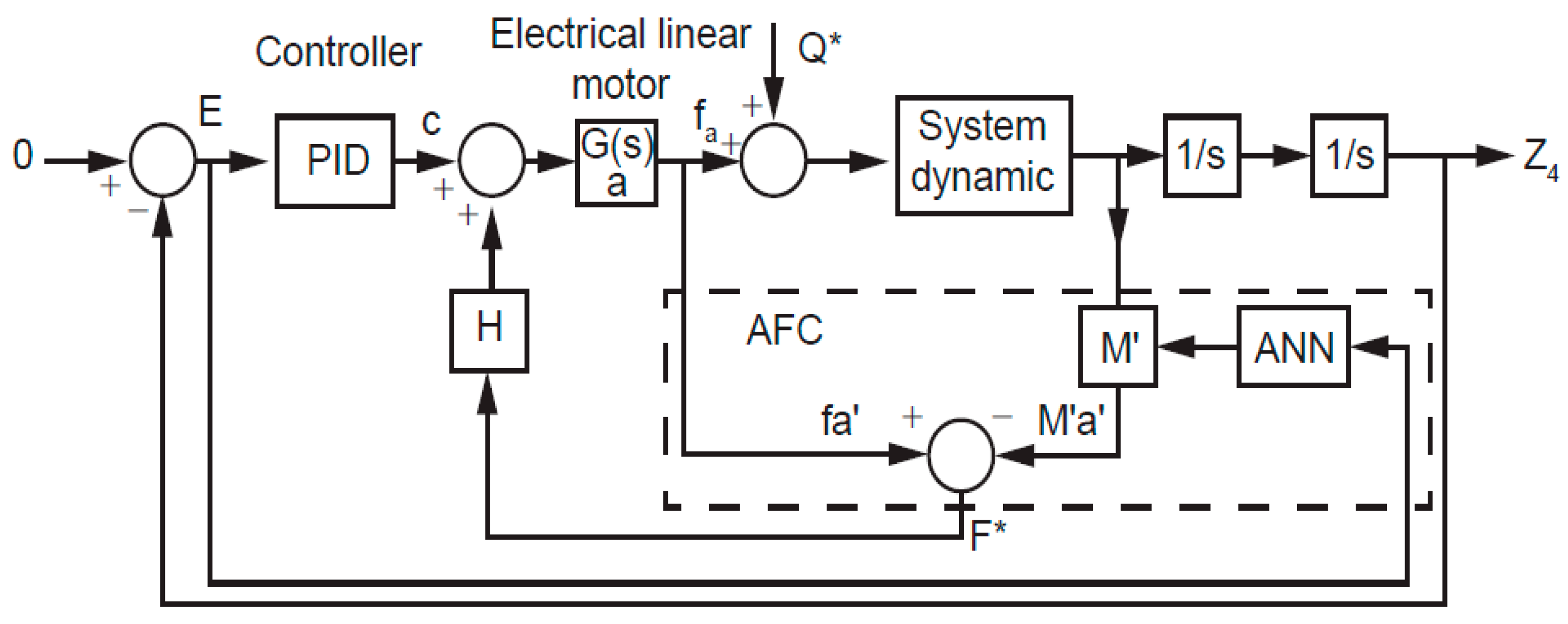
Active force control (AFC) is a disturbance rejection control technique that has been broadly used in the robotic system applications [105]. It was first introduced by Hewit and Burdess in [106]. Recently, the AFC was utilized in the active suspension system to ensure the passenger ride and car stability [107]. Hence, the active force control method was proposed by [108] to increase the robustness of the active seat suspension. The artificial neural network (ANN) was used to approximately estimate the seat and human body weight. The main advantages of the AFC are its disturbance rejection efficiency and simple control algorithm. However, the system can potentially get damaged when the high force is applied. Figure 18 shows the block diagram of the AFC scheme.
The skyhook damped system was integrated with ground-hook damped system in [50]. The skyhook was used to reduce the vibration transmitted to the driver, while the ground-hook was implemented to reduce the relative deflection of the seat suspension.
According to Reference [27], a different type of control method was presented to suppress the driver’s vertical acceleration in the whole low-frequency as well as the human body sensitive frequency range using the power spectrum density (PSD) scaling factor based on the projective chaos synchronization (PCS). The Lyapunov theory was used to validate the stability of the PCS.
The primary and secondary controllers were proposed to attenuate the active vibration of the active seat suspension [109]. The reverse dynamics of the force actuator were considered as a secondary controller where the force feedback was used to track the force of the system. The active seat suspension was considered as a single degree of freedom. The multi-criteria optimization technique was utilized to evaluate the primary controller. Two different masses were selected to examine the performances of the proposed controllers. SEAT method was selected as an optimization technique for different driver masses and different suspension travel range. The experimental results indicated that the vibration of the active seat suspension was reduced by 44.8% compared with that of a passive seat suspension.
The optimal control algorithms were designed to minimize the vertical acceleration at the driver’s hip point where the linear quartic regulator was used as a controller [110]. Table 3 summarizes the existing work in the active seat suspension control in the vertical direction. While Table 4 shows the pros and cons of each control algorithm used in the active seating system.

9. Our Contributions

Our group has been working on the active vibration control of a seating system since 2016 [31,111]. A 5-DOF seat–occupant biodynamic model was developed and applied in vibration control simulation research [67]. A new active vibration control system of a seating suspension structure that combines a traditional rotating actuator and a scissor-like suspension structure was developed to reduce low-frequency vibration and improve ride comfort [72]. The PID, fuzzy PID and state feedback H-infinity controllers were designed and applied to the active vibration control actuator of the seating suspension structure in [20,72]. An analysis of the parameter sensitivity of a 5-DOF model-based Monte Carlo simulation was performed [20]. The measurement data and results recorded from four actual trucks in a field test were applied in the research to identify the 5-DOF system parameters of the human body seating system [20]. The relevant active vibration control of the seating system was simulated in the Simulink software [20].

Research Gaps and Research Questions

Based on the previously published research papers, various vehicle seating suspension structures have been proposed and illustrated in detail in the above sections. However, these structures have a common shortcoming, which is that the seat suspension designs are either expensive or difficult to implement in real commercial vehicles because the size of the seat suspension structures are huge. Therefore, our team are going to design an innovative seat structure which can be practically implemented at a low cost. The detailed seat suspension design structure will be presented in our future work.
In terms of the control algorithms of active seat suspension, to the authors’ best knowledge, the Model Predictive Controller (MPC) technique has not been applied in the active seat suspension system, which encourages the authors to bring the method up for study and implement the method into the vehicle seat suspension system.
System-state estimation and disturbance observers are the core feature of the active seat suspension because they can reduce the number of sensors needed to provide information about the system performance measurements. However, some observers require a mathematical model of high complexity, which is hard to understand. Thus, choosing a more accurately estimation observer for the real model is essential for our research direction.
Based on the above comprehensive research gaps, the following questions are raised:
  • What innovative seat suspension structure should be used to implement the actuator and control algorithm within?
  • What type of MPC can be used to improve the driver comfort for active seat suspension system?
  • How can the Kalman filter be used to estimate the disturbances for active vibration seating system?

10. Conclusions

This paper attempts to provide a systematic literature review on the active vibration control of seating suspension system. Based on the examined findings, the active seating suspension system is suggested to be the future development trend of the seating suspension system due to the accurate force control, good ride quality and handling performances. Fundamental concepts of the biodynamic model of the seating suspension system and human body have been studied. The bio-dynamic models are categorized into three groups: the lumped mass-spring-dashpot model, finite element analysis model and multi-body human model. Degrees of freedom of the lumped mass-spring-dashpot models such as 1 DOF and 2 DOF models are determined based on the number of the independent coordinates to which the oscillators are referred. Three types of the ride comfort assessment strategies of frequency weighted RMS acceleration, VDV and SEAT values have been illustrated. The paper has also summarized the control strategies that have been applied in the active seating suspension system and evaluated their performances. The research gaps have been identified where research questions have been raised and will be answered in our future work. The authors have proposed the control algorithm of the model predictive control to be applied in the active seating suspension system.

Author Contributions

M.A.-A. analyzed the data; M.A.-A. and X.W. contributed reagents/materials/analysis tools; M.A.-A. and X.W. wrote the paper. All authors have read and agreed to the published version of the manuscript.

Funding

This research was funded by Australian Research Council grant number LP160100132.

Conflicts of Interest

The authors declare no conflict of interest.

References

  1. Paddan, G.; Griffin, M. Effect of seating on exposures to whole-body vibration in vehicles. J. Sound Vib. 2002, 253, 215–241. [Google Scholar] [CrossRef]
  2. Cinquemani, S.; Cutini, M.; Abbati, G.; Meloro, G.; Sabbioni, E. Experimental Assessment of the Effect of Different Tires on Comfort of Construction Truck Operators. In Special Topics in Structural Dynamics; Springer: Cham, Germany, 2019; Volume 5, pp. 249–257. [Google Scholar]
  3. Demic, M.; Lukic, J.; Milic, Z. Some aspects of the investigation of random vibration influence on ride comfort. J. Sound Vib. 2002, 253, 109–128. [Google Scholar] [CrossRef]
  4. Pope, M.H.; Magnusson, M.; Wilder, D.G. Low Back Pain and Whole Body Vibration. Clin. Orthop. Relat. Res. 1998, 354, 241–248. [Google Scholar] [CrossRef] [PubMed]
  5. Mansfield, N.J. Impedance methods (apparent mass, driving point mechanical impedance and absorbed power) for assessment of the biomechanical response of the seated person to whole-body vibration. Ind. Health 2005, 43, 378–389. [Google Scholar] [CrossRef] [Green Version]
  6. Wang, W.; Rakheja, S.; Boileau, P.-É. Relationship between measured apparent mass and seat-to-head transmissibility responses of seated occupants exposed to vertical vibration. J. Sound Vib. 2008, 314, 907–922. [Google Scholar] [CrossRef]
  7. Kumar, V.; Saran, V. Seat-to-Head Transmissibility and Reading Discomfort of the Seated Subjects Exposed to Whole Body Vibration. Int. J. Acoust. Vib. 2016, 21, 67–74. [Google Scholar] [CrossRef]
  8. Dobry, M.W.; Hermann, T. A comparison of human physical models used in the ISO 10068: 2012 standard based on power distribution. Part 1. Vib. Phy. Syst. 2014, 26, 49–56. [Google Scholar]
  9. Coyte, J.L.; Stirling, D.; Du, H.; Ros, M. Seated whole-body vibration analysis, technologies, and modeling: A survey. IEEE Trans. Syst. Man Cybern. Syst. 2015, 46, 725–739. [Google Scholar] [CrossRef]
  10. Wen, S.; Chen, M.Z.; Zeng, Z.; Yu, X.; Huang, T. Fuzzy control for uncertain vehicle active suspension systems via dynamic sliding-mode approach. IEEE Trans. Syst. Man Cybern. Syst. 2016, 47, 24–32. [Google Scholar] [CrossRef]
  11. Huang, Y.; Na, J.; Wu, X.; Liu, X.; Guo, Y. Adaptive control of nonlinear uncertain active suspension systems with prescribed performance. ISA Trans. 2015, 54, 145–155. [Google Scholar] [CrossRef]
  12. Zhao, F.; Ge, S.S.; Tu, F.; Qin, Y.; Dong, M. Adaptive neural network control for active suspension system with actuator saturation. IET Control Theory Appl. 2016, 10, 1696–1705. [Google Scholar] [CrossRef]
  13. Ning, D.; Du, H.; Sun, S.; Li, W.; Li, W. An energy saving variable damping seat suspension system with regeneration capability. IEEE Trans. Ind. Electron. 2018, 65, 8080–8091. [Google Scholar] [CrossRef] [Green Version]
  14. Du, H.; Li, W.; Zhang, N. Integrated seat and suspension control for a quarter car with driver model. IEEE Trans. Veh. Technol. 2012, 61, 3893–3908. [Google Scholar]
  15. Devdutt, M. Active vibration control of passenger seat with HFPIDCR controlled suspension alternatives. Int. J. Mech. Mechatron. Eng. 2016, 10, 916–923. [Google Scholar]
  16. Wang, K.; Gao, F. Vibration Isolation Analysis and Optimization of Commercial Vehicle Cab Suspension System. In SAE Technical Paper 0148-7191; SAE, 2018; Available online: https://www.sae.org/publications/technical-papers/content/2018-01-1405/ (accessed on 8 February 2020).
  17. Kumbhar, P.B.; Xu, P.; Yang, J.J. A Literature Survey of Biodynamic Models for Whole Body Vibration and Vehicle Ride Comfort. In Proceedings of the ASME 2012 International Design Engineering Technical Conferences and Computers and Information in Engineering Conference, Chicago, IL, USA, 12–15 August 2012; American Society of Mechanical Engineers Digital Collection: Chicago, IL, USA, 2012; pp. 671–687. [Google Scholar]
  18. Choi, S.; Choi, J.; Lee, Y.; Han, M. Vibration control of an ER seat suspension for a commercial vehicle. J. Dyn. Sys. Meas. Control 2003, 125, 60–68. [Google Scholar] [CrossRef]
  19. Liang, C.C.; Chiang, C.F. A study on biodynamic models of seated human subjects exposed to vertical vibration. Int. J. Ind. Ergon. 2006, 36, 869–890. [Google Scholar] [CrossRef]
  20. Wang, W.; Rakheja, S.; Boileau, P.É. Effects of sitting postures on biodynamic response of seated occupants under vertical vibration. Int. J. Ind. Ergon. 2004, 34, 289–306. [Google Scholar] [CrossRef]
  21. Wang, X.; Bi, F.; Du, H. Reduction of low frequency vibration of truck driver and seating system through system parameter identification, sensitivity analysis and active control. J. Mech. Syst. Signal Process. 2018, 105, 16–35. [Google Scholar] [CrossRef]
  22. Kitazaki, S.; Griffin, M.J. A modal analysis of whole-body vertical vibration, using a finite element model of the human body. J. Sound Vib. 1997, 200, 83–103. [Google Scholar] [CrossRef]
  23. Kong, W.Z.; Goel, V.K. Ability of the finite element models to predict response of the human spine to sinusoidal vertical vibration. Spine 2003, 28, 1961–1967. [Google Scholar] [CrossRef]
  24. Amirouche, F.; Ider, S. Simulation and analysis of a biodynamic human model subjected to low accelerations—A correlation study. J. Sound Vib. 1988, 123, 281–292. [Google Scholar] [CrossRef]
  25. Qassem, W. Model prediction of vibration effects on human subject seated on various cushions. Med. Eng. Phys. 1996, 18, 350–358. [Google Scholar] [CrossRef]
  26. Coermann, R.R. The mechanical impedance of the human body in sitting and standing position at low frequencies. Hum. Factors Ergon. Soc. 1962, 4, 227–253. [Google Scholar] [CrossRef] [PubMed]
  27. Wen, G.; Zhang, Z.; Yao, S.; Yin, H.; Chen, Z.; Xu, H.; Ma, C. Vibration control for active seat suspension system based on projective chaos synchronisation. Int. J. Veh. Des. 2012, 58, 1–14. [Google Scholar] [CrossRef]
  28. Magid, E.B.; Coermann, R. The reaction of the human body to extreme vibrations. Proc. Inst. Environ. Sci. 1960, 135, 37. [Google Scholar]
  29. Muksian, R.; Nash, C., Jr. On frequency-dependent damping coefficients in lumped-parameter models of human beings. J. Biomech. 1976, 9, 339–342. [Google Scholar] [CrossRef] [Green Version]
  30. Boileau, P.-É.; Rakheja, S. Whole-body vertical biodynamic response characteristics of the seated vehicle driver: Measurement and model development. Int. J. Ind. Ergon. 1998, 22, 449–472. [Google Scholar] [CrossRef]
  31. Zhao, Y.; Wang, X. A Review of Low-Frequency Active Vibration Control of Seat Suspension Systems. J. Appl. Sci. 2019, 9, 3326. [Google Scholar] [CrossRef] [Green Version]
  32. Randall, J.; Matthews, R.; Stiles, M. Resonant frequencies of standing humans. Ergonomics 1997, 40, 879–886. [Google Scholar] [CrossRef]
  33. Ning, D.; Du, H.; Sun, S.; Li, W.; Zhang, B. An innovative two-layer multiple-DOF seat suspension for vehicle whole body vibration control. IEEE Trans. Mechatron. 2018, 23, 1787–1799. [Google Scholar] [CrossRef]
  34. Paddan, G.; Griffin, M. Evaluation of whole-body vibration in vehicles. J. Sound Vib. 2002, 253, 195–213. [Google Scholar] [CrossRef]
  35. ISO. Mechanical Vibration and Shock: Evaluation of Human Exposure to Whole-Body Vibration. Part 1, General Requirements: International Standard ISO 2631-1: 1997 (E); ISO: Geneva, Switzerland, 1997. [Google Scholar]
  36. ISO. ISO 8041-1:2017. Human Response to Vibration—Measuring Instrumentation—Part 1: General Purpose Vibration Meters. Available online: https://www.sis.se/api/document/preview/921825/ (accessed on 28 December 2019).
  37. Griffin, M.J. A comparison of standardized methods for predicting the hazards of whole-body vibration and repeated shocks. J. Sound Vib. 1998, 215, 883–914. [Google Scholar] [CrossRef]
  38. Ciloglu, H.; Alziadeh, M.; Mohany, A.; Kishawy, H. Assessment of the whole body vibration exposure and the dynamic seat comfort in passenger aircraft. Int. J. Ind. Ergon. 2015, 45, 116–123. [Google Scholar] [CrossRef]
  39. Martins, I.; Esteves, M.; da Silva, F.P.; Verdelho, P. Electromagnetic Hybrid Active-Passive Vehicle Suspension System. In Proceedings of the 1999 IEEE 49th Vehicular Technology Conference (Cat. No. 99CH36363), Houston, TX, USA, 16–20 May 1999; IEEE: Piscataway, NJ, USA, 1999; Volume 3, pp. 2273–2277. [Google Scholar]
  40. Alkhatib, R.; Jazar, G.N.; Golnaraghi, M. Optimal design of passive linear suspension using genetic algorithm. J. Sound Vib. 2004, 275, 665–691. [Google Scholar] [CrossRef]
  41. Du, X.-M.; Yu, M.; Fu, J.; Peng, Y.-X.; Shi, H.-F.; Zhang, H. H∞ control for a semi-active scissors linkage seat suspension with magnetorheological damper. J. Intell. Mater. Syst. Struct. 2019, 30, 708–721. [Google Scholar] [CrossRef]
  42. Ning, D.; Du, H.; Sun, S.; Zheng, M.; Li, W.; Zhang, N.; Jia, Z. An Electromagnetic Variable Stiffness Device for Semi-Active Seat Suspension Vibration Control. IEEE Trans. Ind. Electron. 2019. [Google Scholar] [CrossRef]
  43. Gad, S.; Metered, H.; Bassuiny, A.; Abdel Ghany, A.M. Multi-objective genetic algorithm fractional-order PID controller for semi-active magnetorheologically damped seat suspension. J. Vib. Control 2017, 23, 1248–1266. [Google Scholar] [CrossRef]
  44. Yang, Z.; Liang, S.; Zhou, Y.; Zhao, D. Sliding Mode Control for Vibration Comfort Improvement of a 7-DOF Nonlinear Active Vehicle Suspension Model. J. Robot. Mechtron. 2019, 31, 95–103. [Google Scholar] [CrossRef]
  45. Ning, D.; Sun, S.; Zhang, F.; Du, H.; Li, W.; Zhang, B. Disturbance observer based Takagi-Sugeno fuzzy control for an active seat suspension. J. Mech. Syst. Signal Process. 2017, 93, 515–530. [Google Scholar] [CrossRef] [Green Version]
  46. Nevala, K.; Kangaspuoskari, M.; Leinonen, T. Development of an Active Suspension Mechanism for the Seat Vibration Damping. In Proceedings of the 4th IASTED International Conference: Robotics and Manufacturing, Honolulu, HI, USA, 19–22 August 1996; pp. 337–339. [Google Scholar]
  47. Bai, X.-X.; Jiang, P.; Qian, L.-J. Integrated semi-active seat suspension for both longitudinal and vertical vibration isolation. J. Intell. Mater. Syst. Struct. 2017, 28, 1036–1049. [Google Scholar] [CrossRef]
  48. Li, Y.; Feng, L.; Wang, Y. A cascade control approach to active suspension using pneumatic actuators. Asian J. Control 2019, 21, 70–88. [Google Scholar] [CrossRef] [Green Version]
  49. Ning, D.; Sun, S.; Du, H.; Li, W.; Li, W. Control of a multiple-DOF vehicle seat suspension with roll and vertical vibration. J. Sound Vib. 2018, 435, 170–191. [Google Scholar] [CrossRef]
  50. Kieneke, R.; Graf, C.; Maas, J. Active seat suspension with two degrees of freedom for military vehicles. IFAC Proc. Vol. 2013, 46, 523–529. [Google Scholar] [CrossRef]
  51. Yu, J.-H.; Lee, K.-C.; Park, H.-B.; Choi, Y.-G.; Ryu, K.-H. Development of 2-DOF active seat suspension system for agricultural tractor–design of mechanism and controller. In 2008 Providence, Rhode Island, June 29–July 2, 2008; American Society of Agricultural and Biological Engineers: Rhode Island, RI, USA, 2008; p. 1. Available online: https://elibrary.asabe.org/abstract.asp?aid=25007 (accessed on 8 February 2020).
  52. Boonporm, P.; Houdjaroen, K.; Panchomphu, C. Development of 2 DOF Truck’s Suspension Seat for Improving Ride Comfort. In Proceedings of the 2nd International Symposium on Computer Science and Intelligent Control, Stockholm, Sweden, 21–23 September 2018; ACM: New York, NY, USA, 2018; p. 7. [Google Scholar]
  53. Mandapuram, S.; Rakheja, S.; Boileau, P.E.; Maeda, S.; Shibata, N. Apparent Mass and Seat-to-head Transmissibility Responses of Seated Occupants under Single and Dual Axis Horizontal Vibration. Ind. Health 2010, 48, 698–714. [Google Scholar] [CrossRef] [PubMed] [Green Version]
  54. Mandapuram, S.; Rakheja, S.; Marcotte, P.; Boileau, P.-É. Analyses of biodynamic responses of seated occupants to uncorrelated fore-aft and vertical whole-body vibration. J. Sound Vib. 2011, 330, 4064–4079. [Google Scholar] [CrossRef] [Green Version]
  55. Maciejewski, I.; Krzyzynski, T.; Meyer, H. Modeling and vibration control of an active horizontal seat suspension with pneumatic muscles. J. Vib. Control 2018, 24, 5938–5950. [Google Scholar] [CrossRef]
  56. Hostens, I.; Ramon, H. Descriptive analysis of combine cabin vibrations and their effect on the human body. J. Sound Vib. 2003, 266, 453–464. [Google Scholar] [CrossRef]
  57. Qiu, Y.; Griffin, M.J. Biodynamic Response of the Seated Human Body to Single-axis and Dual-axis Vibration: Effect of Backrest and Non-linearity. Ind. Health 2011, 50, 37. [Google Scholar] [CrossRef] [Green Version]
  58. Stein, G.J.; Zahoranský, R.; Gunston, T.P.; Burström, L.; Meyer, L. Modelling and simulation of a fore-and-aft driver’s seat suspension system with road excitation. Int. J. Ind. Ergon. 2008, 38, 396–409. [Google Scholar] [CrossRef]
  59. Blüthner, R.; Hinz, B.; Menzel, G.; Schust, M.; Seidel, H. On the significance of body mass and vibration magnitude for acceleration transmission of vibration through seats with horizontal suspensions. J. Sound Vib. 2006, 298, 627–637. [Google Scholar] [CrossRef]
  60. Gündoğdu, Ö. Optimal seat and suspension design for a quarter car with driver model using genetic algorithms. Int. J. Ind. Ergon. 2007, 37, 327–332. [Google Scholar] [CrossRef]
  61. Kuznetsov, A.; Mammadov, M.; Sultan, I.; Hajilarov, E. Optimization of a quarter-car suspension model coupled with the driver biomechanical effects. J. Sound Vib. 2011, 330, 2937–2946. [Google Scholar] [CrossRef]
  62. Rajendiran, S.; Lakshmi, P. Simulation of PID and fuzzy logic controller for integrated seat suspension of a quarter car with driver model for different road profiles. J. Mech. Sci. Technol. 2016, 30, 4565–4570. [Google Scholar] [CrossRef]
  63. Singh, D. Ride comfort analysis of passenger body biodynamics in active quarter car model using adaptive neuro-fuzzy inference system based super twisting sliding mode control. J. Vib. Control 2019, 25, 1866–1882. [Google Scholar] [CrossRef]
  64. Devdutt. Passenger Seat Vibration Comparison Using ANFIS Control in Active Quarter Car Model. Int. J. Mech. Mechatron. Eng. 2017, 11, 1–7. [Google Scholar]
  65. Stein, G.J. A driver’s seat with active suspension of electro-pneumatic type. J. Vib. Acoust. 1997, 119, 230–235. [Google Scholar] [CrossRef]
  66. Shurpali, M.V.; Mullinix, L. An Approach for Validation of Suspension Seat for Ride Comfort using Multi-Body Dynamics. In SAE Technical Paper 0148-7191; SAE International, 2011; Available online: https://www.sae.org/publications/technical-papers/content/2011-01-0434/ (accessed on 8 February 2020).
  67. Quaglia, G.; Sorli, M. Air suspension dimensionless analysis and design procedure. Intl. J. Veh. Mech. Mobil. 2001, 35, 443–475. [Google Scholar] [CrossRef]
  68. Jin, A.; Zhang, W.; Wang, S.; Yang, Y.; Zhang, Y. Modeling air-spring suspension system of the truck driver seat. Intl. J. Commer. Veh. 2014, 7, 157–162. [Google Scholar] [CrossRef]
  69. Maciejewski, I.; Glowinski, S.; Krzyzynski, T.J.M. Active control of a seat suspension with the system adaptation to varying load mass. Mechtronics 2014, 24, 1242–1253. [Google Scholar] [CrossRef]
  70. Gan, Z.; Hillis, A.J.; Darling, J. Adaptive control of an active seat for occupant vibration reduction. J. Sound Vib. 2015, 349, 39–55. [Google Scholar] [CrossRef] [Green Version]
  71. Wu, J.D.; Chen, R.J. Application of an active controller for reducing small-amplitude vertical vibration in a vehicle seat. J. Sound Vib. 2004, 274, 939–951. [Google Scholar] [CrossRef]
  72. Zames, G.; Francis, B. Feedback, minimax sensitivity, and optimal robustness. IEEE Trans. Autom. Control 1983, 28, 585–601. [Google Scholar] [CrossRef]
  73. Gu, D.-W.; Petkov, P.; Konstantinov, M.M. Robust Control Design with MATLAB; Springer Science & Business Media: London, UK, 2005; ISBN 978-1-4471-4681-0. [Google Scholar]
  74. Tolaimate, I.; Elalami, N. Elalami, Engineering, and Development. Robust Control Problem as H2 and H∞ control problem applied to the robust controller design of Active Queue Management routers for Internet Protocol. Int. J. Syst. Appl. Eng. Dev. 2011, 5, 683–691. [Google Scholar]
  75. Ning, D.; Sun, S.; Zhang, J.; Du, H.; Li, W.; Wang, X. An active seat suspension design for vibration control of heavy-duty vehicles. J. Low Freq. Noise Vib. Act. Control 2016, 35, 264–278. [Google Scholar] [CrossRef]
  76. Ning, D.; Sun, S.; Li, H.; Du, H.; Li, W. Active control of an innovative seat suspension system with acceleration measurement based friction estimation. J. Sound Vib. 2016, 384, 28–44. [Google Scholar] [CrossRef]
  77. Wei, C.; Cai, Y.; Zhang, K.; Wang, Z.; Yu, W. Novel Optimal Design Approach for Output-Feedback H∞ Control of Vehicle Active Seat-Suspension System. Asian J. Control 2018, 22, 411–422. [Google Scholar] [CrossRef]
  78. Gu, Z.; Fei, S.; Zhao, Y.; Tian, E. Robust control of automotive active seat-suspension system subject to actuator saturation. J. Dyn. Sys. Meas. Control 2014, 136, 041022. [Google Scholar] [CrossRef]
  79. Gordon, T.; Marsh, C.; Milsted, M. A comparison of adaptive LQG and nonlinear controllers for vehicle suspension systems. Intl. J. Veh. Mech. Mobil. 1991, 20, 321–340. [Google Scholar] [CrossRef]
  80. Sun, W.; Li, J.; Zhao, Y.; Gao, H.J.M. Vibration control for active seat suspension systems via dynamic output feedback with limited frequency characteristic. Mechtronics 2011, 21, 250–260. [Google Scholar] [CrossRef]
  81. Choi, H.D.; Lee, C.J.; Lim, M.T. Fuzzy Preview Control for Half-vehicle Electro-hydraulic Suspension System. Int. J. Control Autom. Syst. 2018, 16, 2489–2500. [Google Scholar] [CrossRef]
  82. Pang, H.; Wang, Y.; Zhang, X.; Xu, Z. Robust state-feedback control design for active suspension system with time-varying input delay and wheelbase preview information. J. Frankl. Inst. 2019, 356, 1899–1923. [Google Scholar] [CrossRef]
  83. Arunachalam, K.; Jawahar, P.M.; Tamilporai, P. Active suspension system with preview control—A review. In SAE Technical Paper 0148-7191; 2003; Available online: https://www.sae.org/publications/technical-papers/content/2003-28-0037 (accessed on 8 February 2020).
  84. Alfadhli, A.; Darling, J.; Hillis, A.J. The control of an active seat with vehicle suspension preview information. J. Vib. Control 2017, 24, 1412–1426. [Google Scholar] [CrossRef] [Green Version]
  85. Alfadhli, A.; Darling, J.; Hillis, A. The Control of an Active Seat Suspension Using an Optimised Fuzzy Logic Controller, Based on Preview Information from a Full Vehicle Model. Vibration 2018, 1, 3. [Google Scholar] [CrossRef] [Green Version]
  86. Alfadhli, A.; Darling, J.; Hillis, A. An Active Seat Controller with Vehicle Suspension Feedforward and Feedback States: An Experimental Study. Appl. Sci. 2018, 8, 603. [Google Scholar] [CrossRef] [Green Version]
  87. Li, P.; Lam, J.; Cheung, K.C. Multi-objective control for active vehicle suspension with wheelbase preview. J. Sound Vib. 2014, 333, 5269–5282. [Google Scholar] [CrossRef]
  88. Liu, J. Sliding Mode Control Using MATLAB; Academic Press: Cambridge, MA, USA, 2017. [Google Scholar]
  89. Edwards, C.; Alwi, H.; Hamayun, M.T. Fault tolerant control using integral sliding modes. In Advances in Variable Structure Systems and Sliding Mode Control—Theory and Applications; Springer: Berlin/Heidelberg, Germany, 2018; pp. 305–338. [Google Scholar]
  90. Holkar, K.; Waghmare, L. Sliding mode control with predictive PID sliding surface for improved performance. Int. J. Comput. Appl. 2013, 78, 1–5. [Google Scholar]
  91. Ning, D.; Sun, S.; Wei, L.; Zhang, B.; Du, H.; Li, W.J.M. Vibration reduction of seat suspension using observer based terminal sliding mode control with acceleration data fusion. Mechtronics 2017, 44, 71–83. [Google Scholar] [CrossRef]
  92. Lathkar, M.S.; Shendge, P.D.; Phadke, S.B. Active Control of Uncertain Seat Suspension System Based on a State and Disturbance Observer. IEEE Trans. Syst. Man Cybern. Syst. 2017. [Google Scholar] [CrossRef]
  93. Liu, Y.-J.; Zeng, Q.; Liu, L.; Tong, S. An Adaptive Neural Network Controller for Active Suspension Systems with Hydraulic Actuator. IEEE Trans. Syst. Man Cybern. Syst. 2018. [Google Scholar] [CrossRef]
  94. Landau, I.D.; Airimitoaie, T.; Castellanos-Silva, A.; Constantinescu, A. Adaptive and Robust Active Vibration Control; Springer: Berlin/Heidelberg, Germany, 2016. [Google Scholar]
  95. Tzafestas, S.G. Introduction to Mobile Robot Control; Elsevier: Amsterdam, The Netherlands, 2013; ISBN 978-0-12-417049-0. [Google Scholar]
  96. Widrow, B. Pattern recognition and adaptive control. IEEE Trans. Appl. Ind. 1964, 83, 269–277. [Google Scholar] [CrossRef]
  97. Panda, R.C. Introduction to PID Controllers: Theory, Tuning and Application to Frontier Areas; Intechopen: Rijeka, Croatia, 2012; ISBN1 978-953-307-927-1. eBook (PDF); ISBN2 978-953-51-6098-4. [Google Scholar] [CrossRef]
  98. Del Campo, I.; Echanobe, J.; Bosque, G.; Tarela, J.M. Efficient hardware/software implementation of an adaptive neuro-fuzzy system. IEEE Trans. Fuzzy Syst. 2008, 16, 761–778. [Google Scholar] [CrossRef]
  99. Biglarbegian, M.; Melek, W.; Golnaraghi, F. A novel neuro-fuzzy controller to enhance the performance of vehicle semi-active suspension systems. Veh. Syst. Dyn. Int. J. Veh. Mech. Mob. 2008, 46, 691–711. [Google Scholar] [CrossRef]
  100. Aldair, A.A.; Wang, W.J. A neurofuzzy controller for full vehicle active suspension systems. J. Vib. Control 2012, 18, 1837–1854. [Google Scholar] [CrossRef]
  101. Nguyen, S.D.; Nguyen, Q.H.; Choi, S.-B. Hybrid clustering based fuzzy structure for vibration control—Part 1: A novel algorithm for building neuro-fuzzy system. J. Mech. Syst. Signal Process. 2015, 50, 510–525. [Google Scholar] [CrossRef]
  102. Nguyen, S.D.; Nguyen, Q.H.; Choi, S.-B. A hybrid clustering based fuzzy structure for vibration control—Part 2: An application to semi-active vehicle seat-suspension system. J. Mech. Syst. Signal Process. 2015, 56, 288–301. [Google Scholar] [CrossRef]
  103. Tsampardoukas, G.; Stammers, C.W.; Guglielmino, E. Hybrid balance control of a magnetorheological truck suspension. J. Sound Vib. 2008, 317, 514–536. [Google Scholar] [CrossRef]
  104. Demir, O.; Keskin, I.; Cetin, S. Modeling and control of a nonlinear half-vehicle suspension system: A hybrid fuzzy logic approach. J. Nonlinear Dyn. 2012, 67, 2139–2151. [Google Scholar] [CrossRef]
  105. Kwek, L.; Wong, E.; Loo, C.K.; Rao, M. Application of active force control and iterative learning in a 5-link biped robot. J. Intell. Robot. Syst. 2003, 37, 143–162. [Google Scholar] [CrossRef]
  106. Hewit, J.; Burdess, J. Fast dynamic decoupled control for robotics, using active force control. J. Mech. Mach. Theory 1981, 16, 535–542. [Google Scholar] [CrossRef]
  107. Alexandru, C.; Alexandru, P. The virtual prototype of a mechatronic suspension system with active force control. WSEAS Trans. Syst. 2010, 9, 927–936. [Google Scholar]
  108. Gohari, M.; Tahmasebi, M. Active off-road seat suspension system using intelligent active force control. J. Low Freq. Noise Vib. Act. Control. 2015, 34, 475–489. [Google Scholar] [CrossRef] [Green Version]
  109. Maciejewski, I.; Krzyżyński, T. Control system design of active seat suspensions. J. Theor. Appl. Mech. 2012, 331, 1291–1309. [Google Scholar] [CrossRef]
  110. Kawana, M.; Shimogo, T. Active suspension of truck seat. J. Sound Vib. 1998, 5, 35–41. [Google Scholar] [CrossRef]
  111. Heidarian, A.; Wang, X. Review on Seat Suspension System Technology Development. J. Appl. Sci. 2019, 9, 2834. [Google Scholar] [CrossRef] [Green Version]
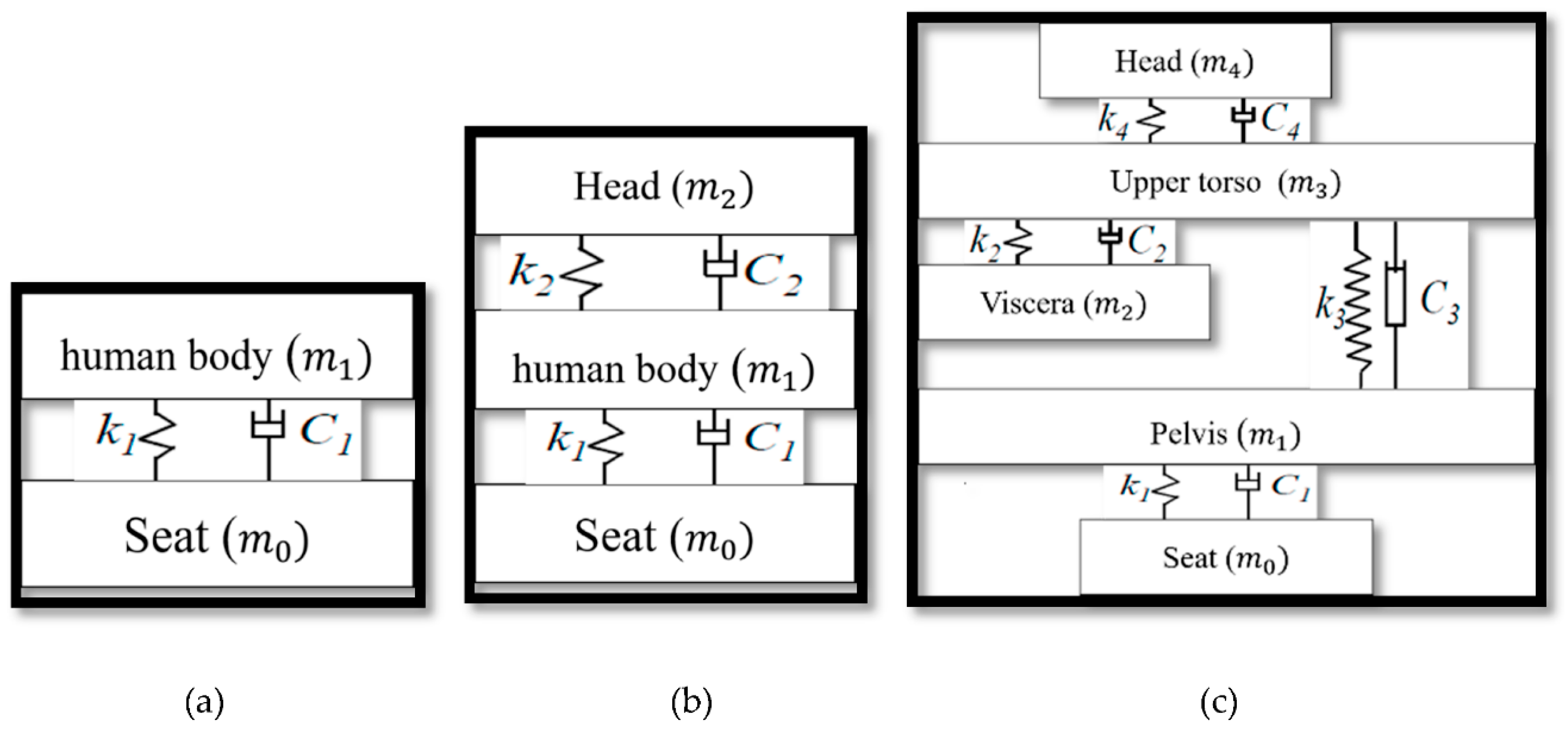
Figure 1. Biodynamic model of the seat with human body. (a) 1 degree of freedom (DOF) representation. (b) 2 DOF representation. (c) 4 DOF representation.
Applsci 10 01148 g001
Figure 2. Whole body vibration (WBV) of the human body [9].
Applsci 10 01148 g002
Figure 3. Seat suspension system. (a) Passive seat suspension. (b) Active seat suspension [45].
Applsci 10 01148 g003
Figure 4. CAD model of the seating suspension structure [43].
Applsci 10 01148 g004
Figure 5. Multiple DOF active seating suspension system [49].
Applsci 10 01148 g005
Figure 6. Integrated active quarter suspension and seat suspension system [64].
Applsci 10 01148 g006
Figure 7. Scissor structure of active seating suspension system [64].
Applsci 10 01148 g007
Figure 8. Active seating suspension system structure [69].
Applsci 10 01148 g008
Figure 9. CAD model of active seating suspension system [50].
Applsci 10 01148 g009
Figure 10. Mechanical design of active seating suspension system [70].
Applsci 10 01148 g010
Figure 11. Structure of active seating system [71].
Applsci 10 01148 g011
Figure 12. Active seating suspension system scheme [51].
Applsci 10 01148 g012
Figure 13. Standard H configuration [73].
Applsci 10 01148 g013
Figure 14. System trajectory of sliding mode controller (SMC) with sliding surface [90].
Applsci 10 01148 g014
Figure 15. Adaptive block diagram representations [95].
Applsci 10 01148 g015
Figure 16. ANFIS structure [99].
Applsci 10 01148 g016
Figure 17. Hybrid structure of adaptive neuro fuzzy interference system (ANFIS) and super twisting sliding mode controller (ASTSMC) [63].
Applsci 10 01148 g017
Figure 18. Representation block of active force control scheme [108].
Applsci 10 01148 g018
Table 1. Comfort level scales of the ISO standard [35].
Weighted Acceleration (m/s2)ISO Comfort Level
<0.315Not uncomfortable
0.315–0.63A little uncomfortable
0.5–1Fairly uncomfortable
0.8–1.6Uncomfortable
1.25–2.5Very uncomfortable
>2Extremely uncomfortable
Table 2. Summary of the current active seat suspension systems in multiple vibration directions.
References Type of Actuator SystemDegree of Freedom Summary
[48]Pneumatic actuator Vertical and lateral translationDecoupled controllers were designed in the frequencies between 0.5 and 1 Hz. Experimentally measured vibration amplitude reduction in a single direction is 70%. Reduction of 20% is evident when the lateral and vertical vibration controls are integrated
[50]Linear actuator + Air spring Vertical and lateral translation Dynamic feedforward Controller (DFC) and Hybrid Vibration Control (HVC) were used. Experimentally measured vibration amplitude reductions in the vertical direction are 39% and 36% using HVC and DFC, respectively. No reduction in the lateral direction was observed.
[51]Hydraulic actuatorVertical and
pitch motions
Fast Fourier Transform (FFT) analysis based on ISO 5007.
The results showed that the active seat suspension is stable in the frequency range of 0–5 Hz.
[49]Rotary servo motors Vertical and roll motion Two decoupled controllers were implemented. Experimentally measured vibration amplitude reductions in FW-RMS are 29.8% in health evaluation and 23.6% in ride comfort.
Table 3. Summary of recent work of active seat suspension control in the vertical vibration direction.
ReferencesControl
Methods
Actuator
Type
Biodynamic
Model
Summary
[76]H
With friction compensation
Rotary Servo motors1 DOF
seat suspension model
Experimentally measured RMS Reduction by 57%, VDV and SEAT reduction by approximately 35%
[75]H
with friction compensation
Rotary servo motors2 DOF
seat suspension model
Experimentally measured RMS reduction by 32%, VDV and SEAT reduction by approximately 43%
[45]H
with disturbance observer-based T-S fuzzy
Rotary servo motors2 DOF
seat suspension model
Driver mass variation was considered in the design.
Experimentally measured RMS reduction by 45.5%
[77,78]H-3 DOF
quarter-car suspension model
Numerical results.
Time domain results
[80]H-3 DOF
seat suspension model
Finite frequency range.
Numerical results. Acceleration PSD plots and Time domain results.
[92]SMC
State observer
and disturbance observer are used to estimate the uncertainty
-8 DOF
quarter-car suspension model and passenger model
Simulated SEAT reduction by 80%. RMS Reduction by 77.6%
[91]TSMC
State observer are used to reduce the SMC chatter.
Disturbance observer is used to estimate the absolute seat velocity.
Rotary servo motors6 DOF
seat and passenger car quarter suspension models
Experimentally measured RMS reduction by 54.6%, VDV reduction in by 32.6% and SEAT reduction by 34.1%
[69]Primary and secondary controller with adaptation mechanism Hydraulic shock absorber and pneumatic spring 1 DOF
seat suspension model
Experimentally measured reduction of SEAT value by 45% with low human body mass (50 kg) and reduction of SEAT value by 38% with high human body mass (120 kg).
[83]PID Controller with Feedforward (preview information) and feedback statesElectromagnetic linear actuator 4 DOF
quarter-car suspension model
Experimentally measured reduction of the SEAT value and RMS acceleration by 25%
[64]SMC and ANFIS -3 DOF
quarter-car suspension model
Numerical simulation with VDV reduction by 71% from the passive to active quarter-car suspension model
Table 4. Comparison of cons and pros of the control types used in the active seat suspension.
Controller TypeAdvantages Disadvantages
H• High stability • High level of mathematical complexity
• Large control efforts
Preview controller• Guarantee good vibration attenuation performance in the vertical direction • Costly
• Consumes energy
• Takes longer time to estimate the road condition
Sliding mode controller• Ensure high stability in presence of the disturbances and noise.• Chatter problem, which leads to system damage.
Adaptive controller• Robust controller.
• Provide high periodic vibration attenuation performance
• The reference model is critical
• Parameter variation
Active Force Control• Efficient to reduce the disturbances
• Simple design
• High force could easily damage the system
PID• Simple.
• Easy-to-implement.
• Low cost control strategies.
• Highly effective.
• Diffident tuning methods for each process
• Difficult to achieve a fast response with small overshoot.