Article

Temperature Dependence of the Fracture Toughness JC of Random Fibrous Material

1
Key Laboratory of Road Construction Technology and Equipment, MOE, Chang’an University, Xi’an 710064, China
2
State Key Laboratory for Strength and Vibration of Mechanical Structures, Shaanxi Engineering Laboratory for Vibration Control of Aerospace Structures, School of Aerospace, Xi’an Jiaotong University, Xi’an 710049, China
3
The 39th Institute of CETC, Xi’an 710065, China
*
Authors to whom correspondence should be addressed.
Appl. Sci. 2020, 10(3), 941; https://doi.org/10.3390/app10030941
Submission received: 8 January 2020 / Revised: 27 January 2020 / Accepted: 30 January 2020 / Published: 1 February 2020
(This article belongs to the Section Materials Science and Engineering)

Abstract

:
The temperature dependence of the fracture toughness JC of a three-dimensional (3D) random fibrous (RF) material, with a porosity of 87% along the through-the-thickness (TTT) direction, was investigated using experiments and the finite element method (FEM) in this study. The temperature considered ranges from 299 to 1273 K. The experimental observations revealed the fracture toughness JC with crack length-to-width ratios of 0.4 and 0.5, which increased from 47.32 to 328.28 J/m2 and from 44.92 to 280.09 J/m2, respectively, as the temperature increased. Then, a 3D FE model, considering the meso-morphology characteristics of the 3D RF material, was developed to simulate a size-scaled compact tension (CT) specimen with a single edge crack. Using the elastic modulus and the fracture strength of the silica fibers at room temperature, we verified the effectiveness of the FE model, then predicted the fracture strength of the silica fibers and the bonding between the fibers at elevated temperatures. In addition, our developed FE model proved to successfully simulate the fracture toughness JC from 299 to 1273 K and reveal the deformation mechanism of the 3D RF material at different temperatures.

1. Introduction

The 3-dimensional (3D) random fibrous (RF) material, sintered by inorganic fibers, is one kind of composite material that is notable for its low weight, high porosity, high specific surface area, remarkable insulation properties, etc. Due to these individual performances, the 3D RF materials possess a wide application in engineering fields, such as a space shuttle’s thermal insulation, building and filtration [1,2,3,4,5]. However, the complicated mechanical-thermal coupled service environments of the space shuttle require that the 3D RF materials possess prominent thermal insulation properties and a good mechanical performance. Moreover, this kind of material is promising, as these materials have, relatively, rather high mechanical features but quite a low crack resistance property at the same time. In addition, the crack resistance is critical for ceramic materials that are acting under extreme thermal and mechanical loads, for example, some structures whose brittle fracture is unendurable, even under random loads [6].
Fracture toughness, as a generic term of the material property for crack resistance evaluations, can be directly applicable to fracture control [7]. Moreover, fracture toughness is also a coarse-graining property—when a crack extension crosses the specimen, it supplies a perceived measurement at a certain dimensional scale of the energy dissipation [8]. In addition, some works focus on the temperature effect on the fracture toughness of brittle materials [9,10]. For example, the micro-scale experiment results reveal that the initiation of small-scale plasticity plays an important role in the brittle-to-ductile transition of the material, such as miniaturized Si, at an elevated temperature. However, the measured fracture toughness JC of some metals in the ductile-to-brittle transition temperature region reveals that there are test specimen size effects, even if the specimen is a standardized specimen [11,12]. In addition, the fracture toughness of composite materials can also be estimated using the J-integral [13,14], which was devised in 1968 by Rice [15] to calculate the strain energy release rate and the energy per unit fracture surface area of the materials.
Up to now, several methods have been developed for estimating the fracture toughness or slow stable crack growth of inelastic or nonlinear materials and metallic materials. For example, the most commercial FE analysis software can be applied to calculate the J-integral at a 2D crack tip or along a 3D crack front for actual structures. Some approaches are used to simulate the damage properties of composite materials, such as using cohesive elements [16], smeared crack models [17] or X-FEM [18]. Each of these requires the fracture toughness as a judging criterion for the failure mode analysis in the simulating process. Furthermore, a representative volume element (RVE), assumed in the micromechanics theory, is associated with the continuum damage mechanics to describe the development of the damage properties. Additionally, thermodynamic models are established to describe the progressive failure performances and to account for the stiffness degradation of the composite materials [19,20,21,22,23].
Although much effort has been invested in the fracture toughness of metals and composite materials, the fracture toughness JC model for the 3D RF material has not been well developed, and the temperature dependence of the fracture mechanism is not revealed either. In the previous work, we studied the fracture toughness (KIC) of 3D RF materials from 299 to 1273 K by experiments and the FEM, just based on the critical load PQ [24] in the load displacement curves of compact tension (CT) experiments. Furthermore, we have also uncovered the fracture mechanism of these 3D RF materials at the crack tip [25]. However, the simulated fracture toughness (KIC) only fits well with the experimental observations at a low temperature. For this reason, the aim of this study is to make clear the difference between the simulated fracture toughness and the experimental results at elevated temperatures. Firstly, we obtained the load–displacement curves using a compact tension specimen, fabricated along the through-the-thickness (TTT) direction of the 3D RF material, calculated the fracture toughness JC and analyzed the variation trend of the fracture toughness. Then, we developed an FE model with a scaled CT specimen shape and predicted the fracture strength of the fibers and the bonding between the fibers at high temperatures. Finally, we simulated the fracture toughness JC using the developed FE model.

2. Experiment Description

2.1. Material

The 3D RF material applied in this study was sintered using a few mullite fibers and a substantial amount of high purity silica fibers. The 3D RF material’s average porosity and density were 87% and 0.28 g/cm³, respectively. The high porosity made the 3D RF material have a low weight, which also reduced the mechanical properties of the material. The detailed sintering process of this material is shown in [26]; only a short introduction is given here. Firstly, the mullite fibers and silica fibers were cut into short fibers (the averaging fiber length and diameter were ~0.6 and ~0.01 mm respectively), then the sintering additive, such as B4C powder and soluble starch, were mixed with the short fibers to produce the slurry. The slurry was evaporated in the vacuum. Then, the fiber body was sintered at 1473 K in a furnace for about 2 h. In this sintering process, the fibers in the body were randomly bonded together. Finally, an RF material with a high porosity was constructed. Moreover, a scanning electron microscope (SEM) image for this 3D RF material’s cross-sectional area viewing along the TTT directions is given in Figure 1. Obviously, this 3D RF material had a high fiber spacing and the fibers were distributed randomly along the TTT direction.

2.2. Compact Tension Specimen

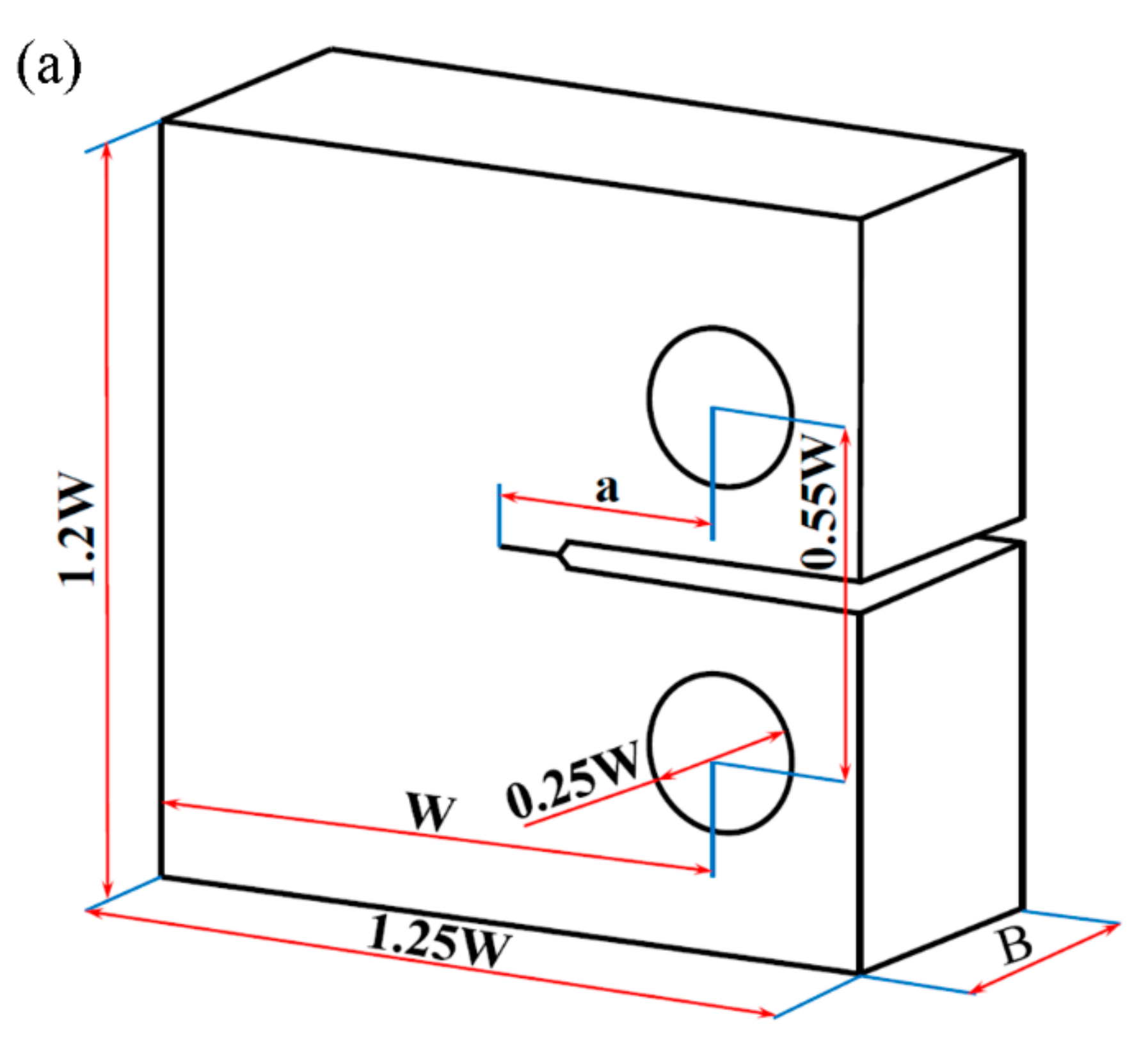
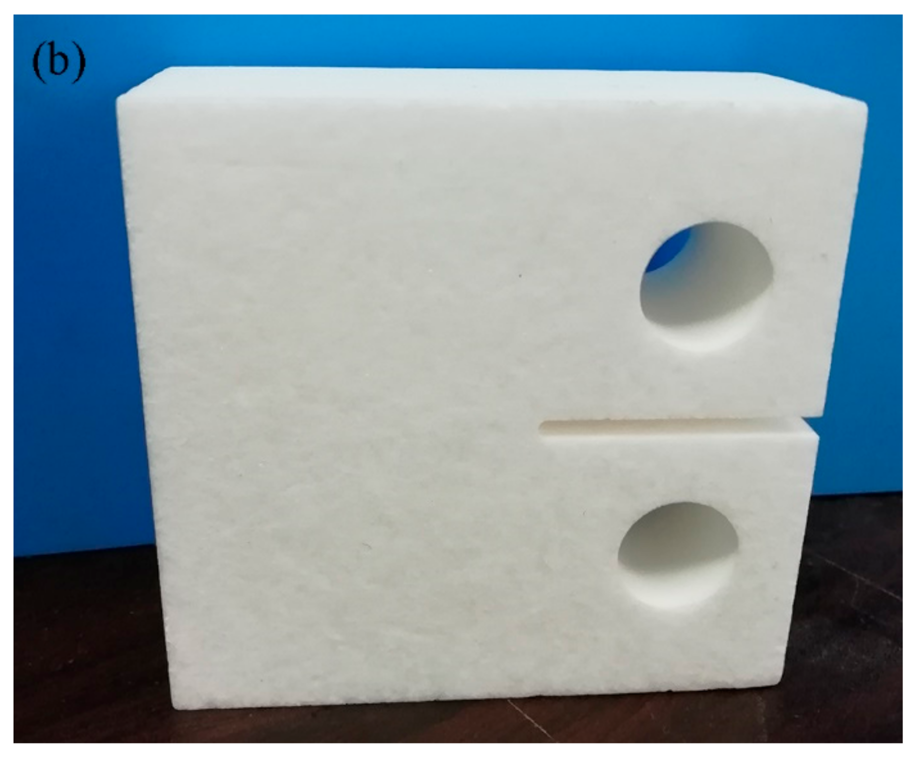
Based on the standard of the American Society for Testing Material (ASTM E399-09), we designed the CT specimen (Figure 2) [27] and obtained the fracture toughness JC from the elevated experiments. The CT specimens were prepared, along the TTT direction, in bulk 3D RF material [28]. Two prefabricated cracks with 25 and 20 mm lengths were created by a fresh razor blade. The CT specimens were loaded at a displacement control mode, with a rate of 1 mm/min, by a material test machine (Z005, Zwick/Roell, Germany). Moreover, the fracture toughness measurement for the CT specimens was accomplished in an elevated temperature mechanics test system from 299 to 1273 K. In the elevated temperature furnace, the set temperature was maintained for 20 min (except the room temperature) before the specimens were tested. Based on our experiment experience, the experimental results and the specimen sizes (the diameter was 20 mm and the height was 30 mm), 20 min was sufficient to bring the specimen to equilibrium in the furnace at a high temperature. In addition, the placed thermocouple was in close proximity to the specimen in the high temperature furnace. Then, we were able to measure the temperature of the specimen. Moreover, in this study, the highest testing temperature was 1273 K, which was determined by the high temperature furnace and the fixture fabricated by the high temperature alloy (their working temperature was also about 1273 K).

2.3. Experimental Results of the Fracture Toughness

Figure 3 only shows the eight typical load–displacement curves of the CT specimens at various experiment temperatures. When the temperature was below 1173 K, the typical brittle fracture mode of the specimen was seen from the load–displacement curves. At 1223 and 1273 K, the softening phenomenon of the specimen was clearly observed. For example, two of the load–displacement curves both contained a nonlinear region before the load peak reached the peak, induced by crack tip blunting, caused by the viscous flow deformation of the fibers and the bonding between the fibers [25]. When the load reached the peak, the load gradually decreased. The millimeter scale crack tip blunting needed to dissipate the extensive energy absorption. Then, the crack caused by the fiber failure initiated from the blunting region. In addition, the similar crack tip blunting deformation of the specimen, at various temperatures, is observed in [25]. For example, using the SEM images of the crack tip of the CT specimens, with a porosity of 89% at different temperatures, we see that the crack tip sizes almost kept constant, and without crack tip blunting deformation, from 299 K to 773 K. After 773 K, the crack tip blunting was obvious, based on the remarkable residual crack sizes of the CT specimens. Those morphological characteristics of the crack tips are similar with CT specimens with a porosity of 87%. In this work, the fracture toughness JC was calculated by [13].
J C = 2 U C B W a g a / W ,   g a / W = 1 + 0.261 1 a / W
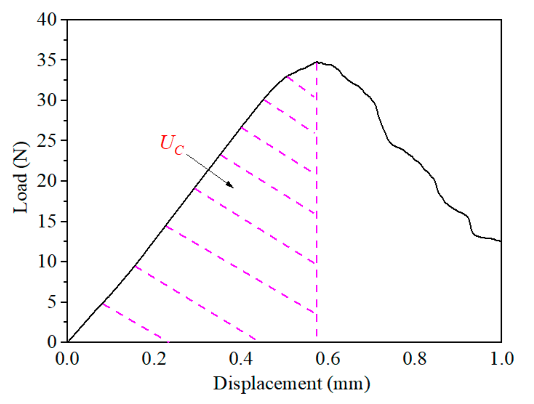
where U C means the area under the load – displacement curve at the maximum load, as indicated in Figure 4. g a / W is a dimensionless constant.
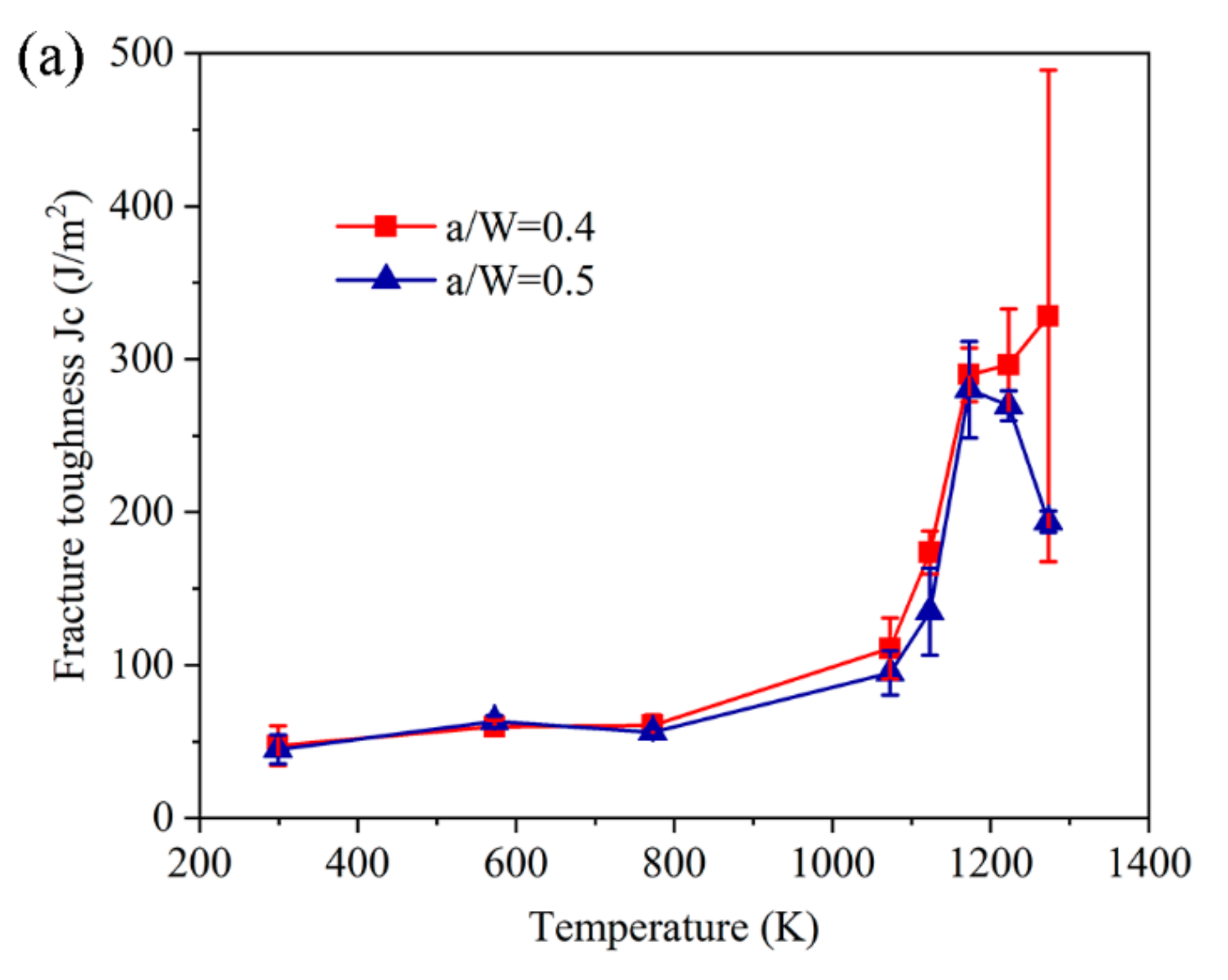
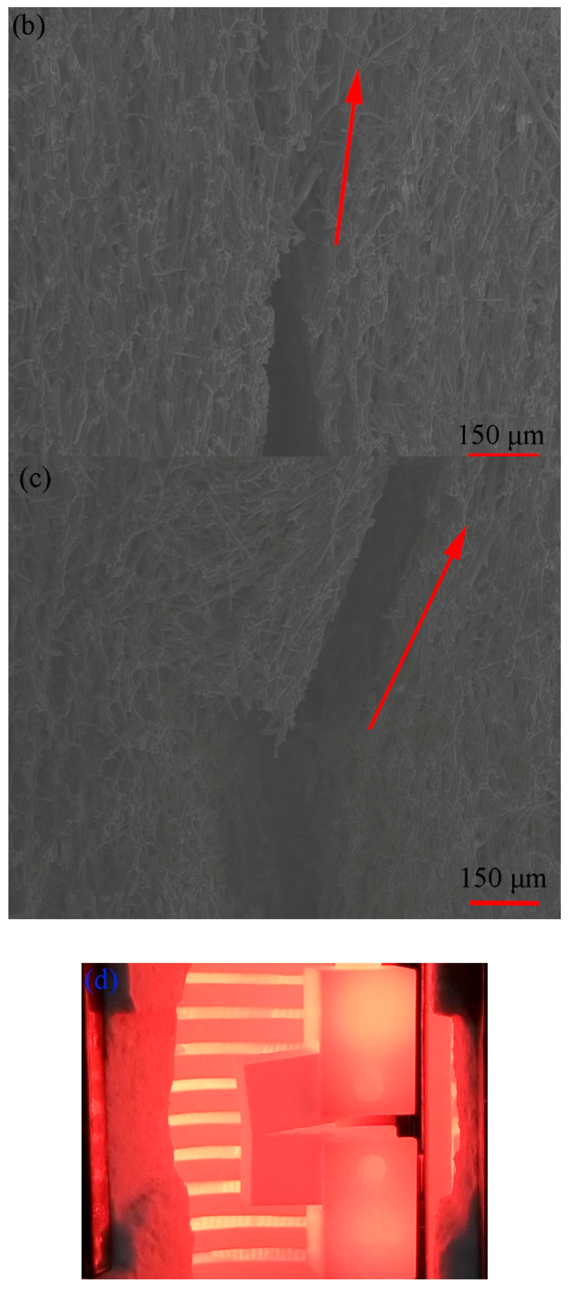
Based on Equation (1), the fracture toughness JC was calculated and plotted in Figure 5a at eight temperatures. Below 1173 K, the fracture toughness with two ratios (a/W=0.4 and 0.5), as the temperature increased, exhibited almost the same variation trend (Figure 5a), and their values were close to each other. For the crack length-to-width ratio of 0.5, the fracture toughness JC increased from 44.92 to 280.09 J/m2 from 299 K to 1173 K, increasing by approximately 524%. For the crack length-to-width ratio of 0.4, the fracture toughness increased by approximately 574% from 47.32 to 328.28 J/m2 between 299 and 1273 K. As temperature increased, the fracture process of the specimen dissipated more energy (Figure 3). This energy dissipation process was attributed to the crack tip blunting caused by the viscous flow deformation in the 3D RF material [25]. In addition, it can be seen that the specimen brittlely fractured at 299 K (Figure 5b) and showed obvious residual crack tip blunting deformation at 1123 K (Figure 5c). In fact, our experimental results and further analysis have confirmed that the viscous flow gave rise to the crack tip blunting. For the crack-tip blunting process, it was a challenge to catch this process in the furnace at elevated temperatures (Figure 5d). However, based on the residual crack size of the specimen (Figure 5b,c), we can still draw the conclusion that the crack tip blunting of the specimen occurred when the temperature was above 773 K [25,27].
When the temperature went beyond 1173 K, two of the temperature dependence of fracture toughness JC curves exhibited different variation trends. For example, the fracture toughness JC from the specimen with a crack length-to-width ratio of 0.5 decreased. However, the fracture toughness JC with a ratio of 0.5 was within the error bars of the fracture toughness JC with a ratio of 0.4. Two facts may explain this phenomenon. On one hand, the 3D RF material had a high fiber spacing and the fibers in the material were distributed randomly. These morphology characteristics easily increased the randomness of the experiment results. On the other hand, above 851.32 K [27], the blunting deformation of the crack tip was the dominant failure mode. This may have increased the uncertainty of the test results. In addition, the pre-crack length of this CT specimen was 25 mm—its effective bearing capacity was lower than the ratio of 0.4, with a pre-crack length of 20 mm, but the crack tip blunting deformation was more obvious.

3. Simulation and Discussion

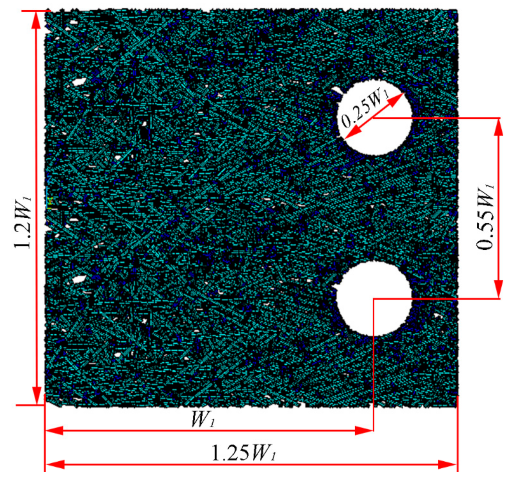
In order to evaluate the blunting deformation and fracture toughness JC of the RF material at an elevated temperature, a 3D FE model, with the morphology characteristics of the RF material and a crack, was developed. This developed FE model was a scaled model with the CT specimen shape. The width W1 of the FE model was made a proportion 1250/21 of the CT specimen size W (Figure 6). The modeling and calculating details are supplied in the Supplementary Material. Furthermore, the whole simulation process was performed in the ANSYS software, and Beam 188 element was applied to study the fibers and the bonding between the fibers. In the CT specimen, there were two holes—this was a limitation in our modeling. In order to overcome this limitation, firstly, we built the FE model based on the set porosity. Then, we used the Boolean operation in ANSYS software to cut two holes in the FE model. In this process, we avoided the Boolean operation affecting the porosity of the FE model. In addition, there were about 39,000 nodes and 41,000 elements in the FE model. The constraint equations between the two RVE (Representative Volume Element) models, the load position and the fixed support are marked in the FE model, as shown in Figure 7. Moreover, based on our experiments of the silica fiber bundle at elevated temperature, we found that the silica fiber bundle exhibited an elastic-fragile behavior. However, the viscous flow deformation temperature of fused SiO2 was about 800 ℃. So, we inferred that the silica fiber exhibited elastic-viscoelastic behavior above the critical temperatures. Moreover, the elementary composition of the bonds was close to the fibers. They should have exhibited a similar elastic-viscoelastic behavior. Therefore, we considered the bond as a short silica fiber in the simulation. However, we assumed that the silica fiber exhibited an elastic-fragile behavior in the simulation. Then, we were able to use the elastic modulus and the fracture strength of the silica fibers to evaluate the mechanical properties of the 3D RF material at elevated temperatures. Thus, we could also overcome the effect of time in the constitutive equation of the viscous flow deformation in the silica fiber.
In addition, all of the silica fibers and bonds in the FE model were considered to be isotropic materials, and then there were only two independent material parameters in constitutive relationships. Moreover, the fibers were all fragile, thus the maximum principal stress criterion was used to predict the onset of their damage. In the analysis, the temperature-dependent elastic modulus and fracture strength were just considered, while the Poisson’s ratio was independent of the temperatures. By doing so, we were able to simulate the mechanical behavior of the 3D RF materials at an elevated temperature.
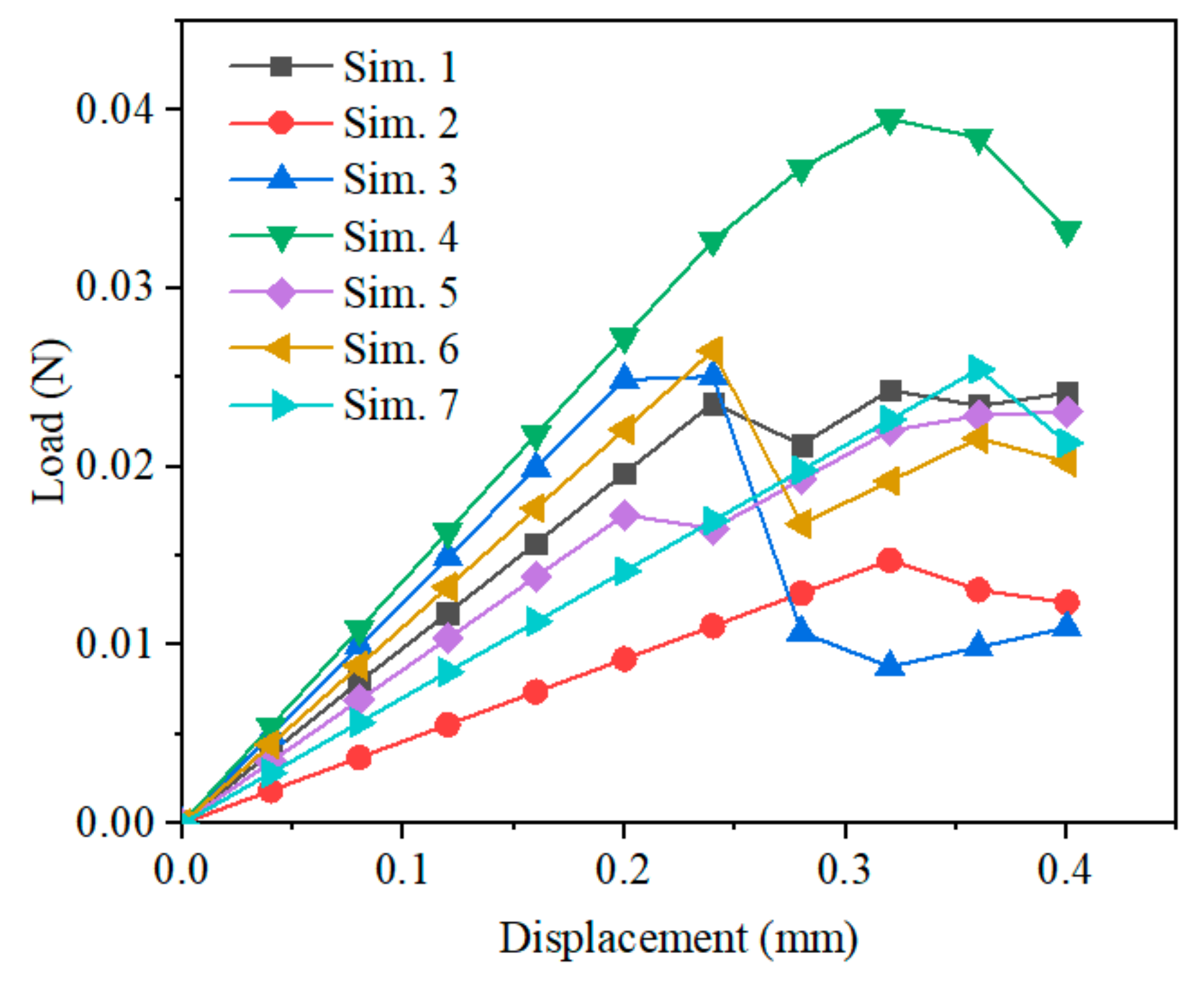
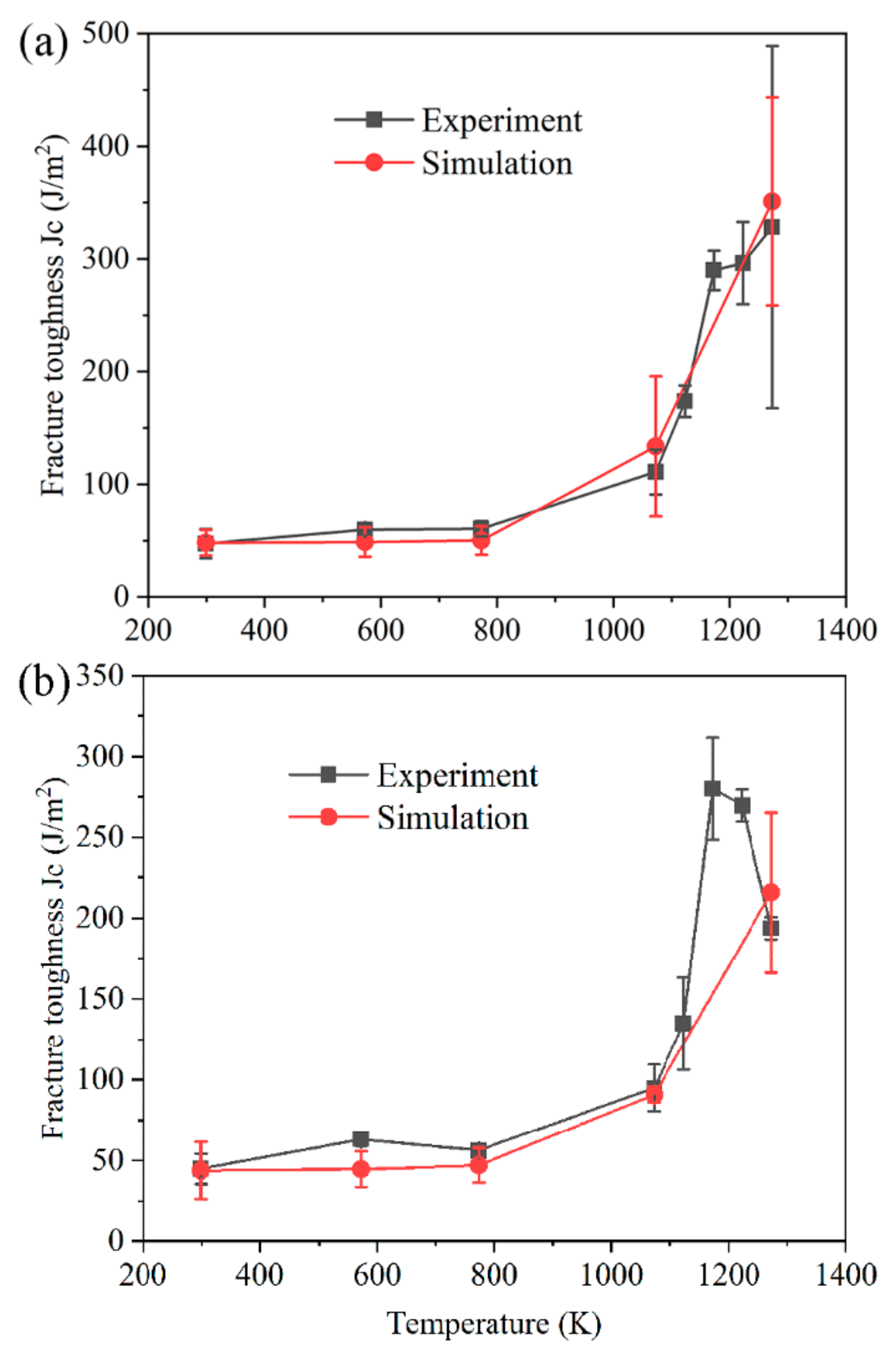
In our previous study, the fracture strength and elastic modulus of the silica fibers were considered as a decreasing variation trend with the temperature. As a result, the simulated fracture toughness showed a decreased variation trend and fit well with the experimental fracture toughness before 773 K [25]. This difference has been attributed to the viscous flow deformation [29] of fibers and bonds between fibers. Using the fracture strength and elastic modulus of the silica fiber at room temperature [26,30], the load–displacement curves from the FE model were simulated and are plotted in Figure 8. Based on these simulated load–displacement curves (Figure 8) and Equation (1), the simulated fracture toughness JC at room temperature was calculated, and the observations showed that the simulated fracture toughness JC of this 3D RF material, with ratios of 0.4 and 0.5, fit well with the experimental results (Figure 9) at 299 K. This observation demonstrates that the developed FE model is useful. In addition, based on the principal stress contours of the FE model as shown in Figure 10 (tensile displacement is 0.4 mm), we found that the maximum principal stress appeared on the fiber surface (Figure 10b), and that the fiber bears a bending deformation (Figure 10b). Our earlier work also revealed that the RF materials fracture through the breaking of the fibers, while almost all of the bonding between the fibers was kept intact when the RF material performed tensile displacement [31].
We showed in our previous study that the elastic modulus of the fibers continuously decreases from 299 to 1273 K [31]. However, the fracture strength of the fibers is hard to determine at elevated temperatures. Using this FE model and the elastic modulus of fibers, we predicted the fracture strength at elevated temperatures based on the predicting process in Figure S3 of the Supplementary Material. Additionally, the predicted tensile strength is plotted in Figure 11. Clearly, the fiber strength almost kept constant from 299 to 1073 K (~3600 MPa), and exhibited a sharp increasing trend as the temperature increased from 1073 to 1273 K (from ~3600 to ~5500 MPa). However, the elastic modulus exhibited a continuous decreasing trend from 299 to 1273 K (from ~78 to ~52 GPa). As shown in Figure 10, the simulated curves of the fracture toughness JC vs. the temperature fitted well with the experimental observations. In fact, such a good fit cannot be obtained when the strength of the silica fibers, as well as the bonding between the fibers, continuously decreases with the increase in temperature. At an elevated temperature, the fibers, and the bonding between the fibers, usually softened and the crack tip of the CT specimen blunted. Therefore, more work is needed to stretch these fibers in this 3D RF material. This phenomenon can also be verified in the typical load–displacement curves from the CT specimen experiments at elevated temperatures (Figure 3).
Moreover, from room temperature to 1273 K, the strength of the fused-silica materials increased from 49.8 ± 3 MPa to 76.9 ± 17 MPa [32]. It increased by approximately 154%. Such an increase in strength at a high temperature has been found to be attributed to the lifted atom mobility, resulting in a limited amount of crack-tip blunting [32,33]. In this work, the fracture strength of the silica fibers increased from 3600 [31] to ~5500 MPa between temperatures of 299 and 1273 K; this increased rate of fracture strength was consistent with the fused-silica materials. In addition, the 3D RF material was sintered using a few mullite fibers and substantial amount of high purity silica fibers in this study. The volume fraction of mullite fibers in the material was very low. Subsequently, we do not discuss the effect of the mullite fibers in this work.

4. Conclusions

In this work, the fracture toughness JC along the TTT direction of the 3D RF material was studied by experimental methods and FE modeling from 299 to 1273K. The experimental observations revealed that the fracture toughness JC almost keeps increasing from 299 to 1273 K. In addition, the experimental fracture toughness JC could be well predicted through the simulation. The main conclusions of this work can be summarized as follows:
(1)
The experimental observations revealed that the fracture toughness JC along the TTT direction of the 3D RF materials, with a crack length-to-width ratio of 0.4, increased by approximately 574% (from 47.32 to 328.28 J/m2) from 299 to 1273K and, when the ratio was 0.5, it increased from 44.92 to 280.09 J/m2 (by approximately 524%) from 299 to 1173 K;
(2)
We developed a scaled FE model with the CT specimen shape and considered the morphological characteristics of the material in this model. Using the material mechanical property of the silica fibers at room temperature, the effectiveness of the developed FE model was verified. The fracture strength of the fibers at elevated temperatures was predicted—it almost kept constant from 299 to 1073 K and sharply increased from 1073 to 1273K;
(3)
Based on the precited fracture strength of the fibers and the developed scaled FE model, the fracture toughness JC was well simulated, and it fit well with experimental observations.

Supplementary Materials

The following are available online at https://www.mdpi.com/2076-3417/10/3/941/s1, Word S1: Supplemental material for Temperature dependence of fracture toughness JC of random fibrous material

Author Contributions

Software, Y.L.; Writing— original draft, D.L.; Writing— review & editing, W.Y. All authors have read and agreed to the published version of the manuscript.

Funding

This study was supported by the NNSF of China (Grant Nos. 11902046, 11872049 and 11632014), the 111 Project (Grant No. B18040), the Chang Jiang Scholar program. This study was also supported by the Fundamental Research Funds for the Central Universities, CHD (Grant Nos. 300102259302 and 300102259305).

Conflicts of Interest

The authors declare no conflict of interest.

References

  1. Hou, Z.; Du, H.; Liu, J.; Hao, R.; Dong, X.; Liu, M. Fabrication and properties of mullite fiber matrix porous ceramics by a TBA-based gel-casting process. J. Eur. Ceram. Soc. 2013, 33, 717–725. [Google Scholar] [CrossRef]
  2. Liu, Q.; Lu, Z.; Hu, Z.; Li, J. Finite element analysis on tensile behaviour of 3D random fibrous materials: Model description and meso-level approach. Mater. Sci. Eng. A 2013, 587, 36–45. [Google Scholar] [CrossRef]
  3. Liu, Q.; Lu, Z.; Zhu, M.; Yang, Z.; Hu, Z.; Li, J. Experimental and FEM analysis of the compressive behavior of 3D random fibrous materials with bonded networks. J. Mater. Sci. 2014, 49, 1386–1398. [Google Scholar] [CrossRef]
  4. Ortiz-Longo, C.R.; White, K.W. Elevated-temperature fracture characterization of advanced fibrous ceramic thermal Insulators. J. Am. Ceram. Soc. 1994, 77, 2703–2711. [Google Scholar] [CrossRef]
  5. Clyne, T.W.; Golosnoy, I.O.; Tan, J.C.; Markaki, A.E. Porous materials for thermal management under extreme conditions. Philos. Trans. 2006, 364, 125–146. [Google Scholar] [CrossRef] [PubMed]
  6. Gogotsi, G.A. Fracture toughness of ceramics and ceramic composites. Ceram. Int. 2003, 29, 777–784. [Google Scholar] [CrossRef]
  7. Sun, B.A.; Wang, W.H. The fracture of bulk metallic glasses. Prog. Mater. Sci. 2015, 74, 211–307. [Google Scholar] [CrossRef]
  8. Ast, J.; Ghidelli, M.; Durst, K.; Göken, M.; Sebastiani, M.; Korsunsky, A. A review of experimental approaches to fracture toughness evaluation at the micro-scale. Mater. Des. 2019, 173, 107762. [Google Scholar] [CrossRef]
  9. Jaya, B.N.; Wheeler, J.M.; Wehrs, J.; Best, J.P.; Soler, R.; Michler, J.; Kirchlechner, C.; Dehm, G. Microscale fracture behavior of single crystal silicon beams at elevated temperatures. Nano Lett. 2016, 16, 7597–7603. [Google Scholar] [CrossRef]
  10. Best, J.P.; Zechner, J.; Wheeler, J.M.; Schoeppner, R.; Morstein, M.; Michler, J. Small-scale fracture toughness of ceramic thin films: The effects of specimen geometry, ion beam notching and high temperature on chromium nitride toughness evaluation. Philos. Mag. 2016, 96, 3552–3569. [Google Scholar] [CrossRef]
  11. Marshall, D.; Cox, B. A J-integral method for calculating steady-state matrix cracking stresses in composites. Mech. Mater. 1988, 7, 127–133. [Google Scholar] [CrossRef]
  12. Petti, J.P.; Dodds, R.H., Jr. Coupling of the Weibull stress model and macroscale models to predict cleavage fracture. Eng. Fract. Mech. 2004, 71, 2079–2103. [Google Scholar] [CrossRef]
  13. Droillard, C.; Lamon, J. Fracture Toughness of 2-D Woven SiC/SiC CVI-Composites with Multilayered Interphases. J. Am. Ceram. Soc. 1996, 79, 849–858. [Google Scholar] [CrossRef]
  14. Pinho, S.T.; Robinson, P.; Iannucci, L. Fracture toughness of the tensile and compressive fibre failure modes in laminated composites. Compos. Sci. Technol. 2006, 66, 2069–2079. [Google Scholar] [CrossRef] [Green Version]
  15. Rice, J.R. A path independent integral and the approximate analysis of strain concentration by notches and cracks. J. Appl. Mech. 1968, 35, 379–386. [Google Scholar] [CrossRef] [Green Version]
  16. Laffan, M.; Pinho, S.; Robinson, P.; McMillan, A. Translaminar fracture toughness testing of composites: A review. Polymer Testing 2012, 31, 481–489. [Google Scholar] [CrossRef]
  17. Pinho, S.; Iannucci, L.; Robinson, P. Physically based failure models and criteria for laminated fibre-reinforced composites with emphasis on fibre kinking. Part II: FE implementation. Compos. Part A Appl. Sci. Manufacturing 2006, 37, 766–777. [Google Scholar] [CrossRef]
  18. Moës, N.; Belytschko, T. Extended finite element method for cohesive crack growth. Eng. Fract. Mech. 2002, 69, 813–833. [Google Scholar] [CrossRef] [Green Version]
  19. Liu, P.; Zheng, J. Recent developments on damage modeling and finite element analysis for composite laminates: A review. Mater. Des. 2010, 31, 3825–3834. [Google Scholar] [CrossRef]
  20. Matzenmiller, A.; Lubliner, J.; Taylor, R. A constitutive model for anisotropic damage in fiber-composites. Mech. Mater. 1995, 20, 125–152. [Google Scholar] [CrossRef]
  21. Kwon, Y.; Liu, C. Study of damage evolution in composites using damage mechanics and micromechanics. Compos. Struct. 1997, 38, 133–139. [Google Scholar] [CrossRef]
  22. Maa, R.-H.; Cheng, J.-H. A CDM-based failure model for predicting strength of notched composite laminates. Compos. Part B Eng. 2002, 33, 479–489. [Google Scholar] [CrossRef]
  23. Camanho, P.P.; Maimí, P.; Dávila, C. Prediction of size effects in notched laminates using continuum damage mechanics. Compos. Sci. Technol. 2007, 67, 2715–2727. [Google Scholar] [CrossRef] [Green Version]
  24. Zhu, X.-K.; Joyce, J. Review of fracture toughness (G, K, J, CTOD, CTOA) testing and standardization. Eng. Fract. Mech. 2012, 85, 1–46. [Google Scholar] [CrossRef] [Green Version]
  25. Li, D.; Yu, W.; Xia, W.; Fang, Q.; Shen, S. Fracture toughness of random fibrous materials with ultrahigh porosity at elevated temperatures. J. Am. Ceram. Soc. 2018, 101, 1323–1332. [Google Scholar] [CrossRef]
  26. Li, D.T.; Xia, W.; Yu, W.S.; Fang, Q.Z.; Shen, S.P. Investigations on the compressive behavior of 3D random fibrous materials at elevated temperatures. Ceram. Int. 2017, 43, 5195–5203. [Google Scholar] [CrossRef]
  27. Li, D.T.; Yu, W.S.; Xia, W.; Fang, Q.Z.; Shen, S.P. Investigations on fracture toughness and fracture surface energy of 3D random fibrous materials at elevated temperatures. Eng. Fract. Mech. 2018, 190, 288–298. [Google Scholar] [CrossRef]
  28. Li, D.T.; Yu, W.S.; Xia, W.; Fang, Q.Z.; Shen, S.P. Porosity Effects on Mechanical Properties of 3D Random Fibrous Materials at Elevated Temperatures. Acta Mech. Solida Sinica 2020, 33, 14–30. [Google Scholar] [CrossRef]
  29. Shinkai, N.; Bradt, R.; Rindone, G.E. Fracture toughness of fused SiO2 and float glass at elevated temperatures. J. Am. Ceram. Soc. 1981, 64, 426–430. [Google Scholar] [CrossRef]
  30. Kourtides, D.A.; Pitts, W.C.; Araujo, M.; Zimmerman, R. High-temperature properties of ceramic fibers and insulations for thermal protection of atmospheric entry and hypersonic cruise vehicles. J. Fire Sci. 1988, 6, 313–332. [Google Scholar] [CrossRef] [Green Version]
  31. Li, D.T.; Xia, W.; Fang, Q.Z.; Yu, W.S.; Shen, S.P. Experimental and numerical investigations on the tensile behavior of 3D random fibrous materials at elevated temperature. Compos. Struct. 2017, 160, 292–299. [Google Scholar] [CrossRef]
  32. Lyons, J.S.; Starr, T.L. Strength and toughness of slip-cast fused-silica composites. J. Am. Ceram. Soc. 1994, 77, 1673–1675. [Google Scholar] [CrossRef]
  33. Brueckner, R. Properties and structure of vitreous silica. J. Non Cryst. Solids 1970, 5, 123–175. [Google Scholar] [CrossRef]
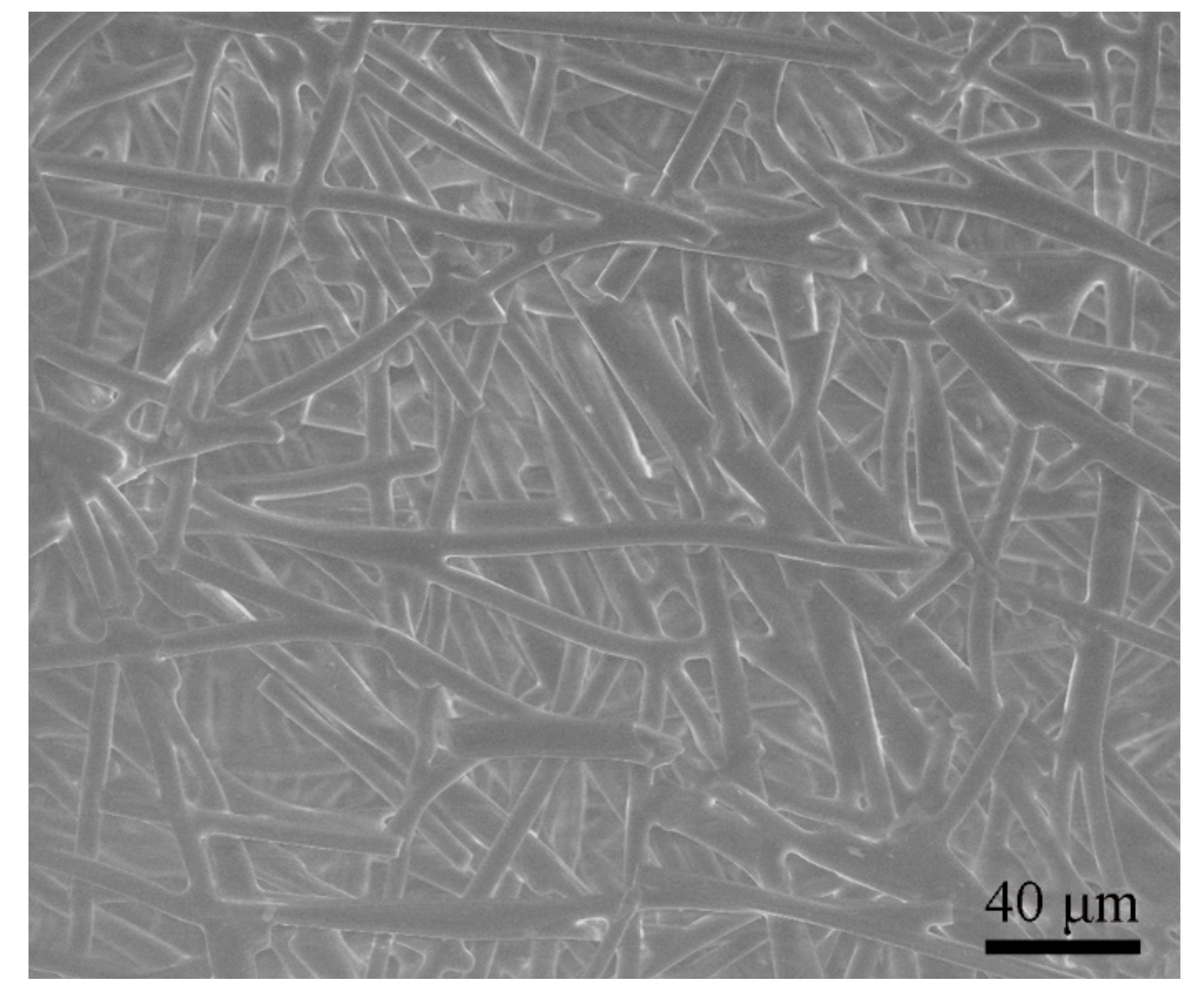
Figure 1. Schematic of a scanning electron microscope (SEM) image for the RF bulk material viewing, along the through-the-thickness (TTT) direction.
Applsci 10 00941 g001
Figure 2. (a) CT specimen schematic diagram (B is the specimen thickness, B = W/2, B = 25 mm, the pre-crack length a is 20 or 25 mm, then a / W = 0.4 or 0.5) and (b) is a photo of the CT specimen.
Applsci 10 00941 g002aApplsci 10 00941 g002b
Figure 3. Typical load – displacement curves from the CT specimen experiments at various temperatures (a / W = 0.4).
Applsci 10 00941 g003
Figure 4. The area under one load – displacement curve of a CT specimen at the maximum load.
Applsci 10 00941 g004
Figure 5. (a) The fracture toughness JC of the CT specimens at various temperatures, with crack length – to – width ratios of 0.4 and 0.5, respectively. The crack tip of the specimen (a / W = 0.4) at (b) 299 K and (c) 1123 K after testing. The red arrows denote the direction of the crack propagation. (d) An image of a CT specimen tested in the furnace.
Applsci 10 00941 g005aApplsci 10 00941 g005b
Figure 6. The FE model of the CT specimen (the width W1 is 1.4L, L is the average fiber length (0.6 mm), the thickness of the FE model B1 is W1/2).
Applsci 10 00941 g006
Figure 7. Constraint equations, load and fixed support shown in the FE model.
Applsci 10 00941 g007
Figure 8. Simulated load–displacement curves from the FE model at room temperature (299 K), where the ratio was 0.5 from crack length to width.
Applsci 10 00941 g008
Figure 9. Experimental and simulated fracture toughness JC of the CT specimen with crack length-to-width ratios of (a) 0.4 and (b) 0.5.
Applsci 10 00941 g009
Figure 10. Principal stress contours of (a) the FE model with a ratio of 0.5 (the tensile displacement was 0.4 mm), (b) the stress contours of the sliced FE model from the red rectangle in (a), and (c) the stress contours of the local structure from the red arrow in (b).
Applsci 10 00941 g010
Figure 11. Elastic modulus [26,30] and the predicted elastic strength of the silica fibers and the bonding between the fibers at various temperatures.
Applsci 10 00941 g011