Article

The Impact of Single- and Multicomponent Liquid Drops on a Heated Wall: Child Droplets

by
Anastasia V. Demidovich
,
Svetlana S. Kropotova
,
Maxim V. Piskunov
,
Nikita E. Shlegel
and
Olga V. Vysokomornaya
*
Power Engineering School, National Research Tomsk Polytechnic University, 30 Lenin Avenue, Tomsk 634050, Russia
*
Author to whom correspondence should be addressed.
Appl. Sci. 2020, 10(3), 942; https://doi.org/10.3390/app10030942
Submission received: 17 January 2020 / Revised: 23 January 2020 / Accepted: 29 January 2020 / Published: 1 February 2020
(This article belongs to the Special Issue Heat and Mass Transfer in Intense Liquid Evaporation)

Abstract

:
This paper presents the experimental research into the impingement of single- and multicomponent liquid drops on a solid wall. We focus on studying the conditions and characteristics of two impact scenarios: rebound and breakup. We performed a comprehensive analysis of the effect of a group of factors on the drop transformation and fragmentation characteristics. These factors include the drop velocity and size, Weber number, impinging angle, wall temperature, thermophysical properties of the wall material, surface roughness, hydrophilic and hydrophobic behavior of the surface, homogeneity and inhomogeneity of the drop composition, as well as viscosity and surface tension of the liquid. We compared the outcomes of one, two, and three drops with the same total volume on a wall. Histograms were plotted of the number and size distribution of the emerging secondary droplets. The results include the critical conditions for the intense breakup of drops. Such factors as wall heating, its roughness, impinging angle, drop size and velocity affected the breakup conditions most notably. The variation of a group of these factors could provide a 2–25-fold increase in the liquid surface area as a result of the impact.

Graphical Abstract

1. Introduction

Nowadays, spray technologies are advancing towards better energy performance in atomization [1,2,3,4]. Gas-vapor-droplet technologies most often involve heterogeneous sprays. Consequently, the priority research line is the enhancement of the secondary atomization of homogeneous and heterogeneous liquids. The most typical secondary atomization technologies are (i) collision between drops and drop impingement on a wall; (ii) explosive breakup of superheated liquid drops; (iii) drop acceleration leading to the catastrophic deformation of its surface and further breakup [1,2,3]. Drop impingement on a wall is the most cost-effective method [1,2,3]. However, there is still no agreement on the conditions for maximizing the number of child droplets. Therefore, it is expedient to analyze the latest achievements of the global scientific community in this area and to outline promising directions for future research [5,6,7,8,9,10].
Liang and Mudawar [1] examined the interaction of a single free-falling water drop with a solid surface. The focus was on the effect of heat fluxes, roughness grade of the surface, as well as drop velocity and size on the impact characteristics. Liang and Mudawar [1] found out that the time of contact between the drop and surface in the case of rebound strongly depended on the thermophysical properties of the wall material. Moreover, the contact time decreased with an increase in the thermal conductivity of the material. They also established that the surface roughness affected the time of drop contact with the surface. In particular, the contact time of a drop noticeably increased with a growth of roughness. With an increase in the drop velocity up to 4 m/s, We = 67, the drop broke up after impinging on the surface. If We < 30, drop rebound took place. At 50 < We < 80, the drop spread over the surface and the resulting lamella disintegrated to form secondary droplets. Moreover, Liang and Mudawar [1] demonstrated the snapshots illustrating details of the drop spreading over a heated surface.
The contact time of a drop with a surface also depends on its hydrophobicity. For example, Tang et al. [5] studied the behavior of a water drop when interacting with superhydrophobic surfaces in the presence of a cold airflow. Experimental studies were carried out at an ambient temperature ranging from −10 °C to 30 °C to investigate the effect of the airflow on a water drop. In the case of superhydrophobic surfaces, a decrease in the contact time of a drop with a surface was observed.
Liang and Mudawar [2] and Šikalo et al. [3] studied heat transfer mechanisms when a drop impinged on a heated surface. An increase in the impact velocity accelerated the spreading velocity during film boiling. In turn, this led to a decrease in the size of secondary droplets. However, the elevated viscosity contributed to an increase in the size of secondary droplets, while a reduction in the surface roughness decreased their size by more than 15%. Moreover, the factor of changing an impingement angle was examined. In particular, the size of child droplets did not depend much on the impingement angle, when it was φ > 45°. However, at φ < 15°, secondary droplets became much smaller.
An experimental study by Clavijo et al. [6] considered the effect of the surface inclination angle on the propagation dynamics of a drop over the surface after an impact. After the drop spreads and reaches its maximum diameter, reverse processes occur, i.e., a drop is formed from the film. For example, a surface slope angle of 67.4° provides maximum droplet spreading. Also, the Weber numbers influence the drop spreading diameter [6]. The maximum drop diameter increases with the Weber number and decreases when the Weber number reaches 2.7. With Weber numbers greater than 5, a drop bounces off a surface.
Tang et al. [5] varied the Weber number from 50 to 1080, using water, isopropanol, and glycerin as well as four materials of a substrate, namely, smooth glass, polyvinyl chloride, wax, and rough glass. A drop of the liquid with a lower surface tension broke up at lower Weber numbers, while an increase in roughness considerably reduced the critical Weber number. Clavijo et al. [6] used lower Weber numbers because the drop diameter was 1.9 ± 0.03 mm, and the average roughness of surfaces was 0.025~6.3 μm. They showed that increasing the Weber number and the surface roughness promoted the drop breakup. In addition to roughness and thermophysical properties of substrate materials, the surface hydrophilicity also had a governing effect on breakup. In particular, Clavijo et al. [6] utilized ultrahydrophilic, hydrophilic, hydrophobic, and superhydrophobic surfaces and performed the experiments at a surface temperature ranging from 125 °C to 415 °C and Weber numbers from 10 to 225. There was some mean temperature range, at which the drop broke up to form a maximum number of child droplets.
Fujimoto et al. [7] generated a sequence of drops to impinge on a surface, so that each successive droplet contacted with a liquid film of a different thickness. They presented the outcomes of two successively moving drops impinging on a surface, varying their diameter from 0.39 mm to 0.65 mm and velocity from 2 m/s to 5 m/s. Metal surface temperatures were 25 °C, 300 °C, and 500 °C, whereas the glass surface temperature remained 25 °C. When two drops fell on the surface one after another, a corona was formed upon the impingement of the second drop. Both drops coalesced, and the resulting rim spread over the surface in a corona-like shape. If the first drop impinged on the surface heated up to 300 °C, it then deformed, forming a thin lamella, and then broke up into smaller fragments. At a surface temperature of 500 °C, a moderate number of child droplets emerged. In addition, surface temperature has a significant effect on drop cooling. Roisman [10] studied the efficiency of cooling water drops falling on the metal disks heated up to 85–400 °C. They used stainless steel and aluminum disks with a surface roughness Ra of 0.4 and 3, respectively. The drop impact velocity was 2.2 m/s. The drop cooling efficiency substantially depended on the surface temperature and was practically independent of the surface roughness.
Williams et al. [11] studied the impact of a nanofluid drop onto a surface (aluminum sheet) with a magnetic field. The effect of surface properties on the dynamic behavior of the drop was analyzed. The behavior of drops on both treated and untreated surfaces had the same tendency: the drops expanded to the maximum diameter (stretch) and then narrowed. However, the treated surface provided a larger drop size, which is explained by the degree of adhesion between the drop and surface.
Experimental findings [1,2,3,4,5,6,7,8] are the basis for developing the models of drop impact on solid walls. Some interesting results in this area were obtained, for instance, by Senda et al. [9], who proposed a model of fuel film formation when impinging a diesel aerosol on a low-temperature wall. The model described the mechanism of fuel film emergence, its breakup and the interaction between the drop having spread over the surface and the drop impinging on it. The theoretical results produced an acceptable fit with experimental data. An important factor was the formation of a thin liquid film on the surface and the contact of all successive droplets with this film. Thus, for instance, Roisman [10] described theoretically the non-stationary laminar viscous flow in a thin layer of a Newtonian fluid. Such a flow appears during the drop impact on a dry surface at high Weber and Reynolds numbers. As a result, Roisman [10] solved the Navier–Stokes equation theoretically for the viscous flow in an expanding drop. He proved that one of the most important parameters characterizing the drop impingement on a surface is the maximum spreading diameter of a drop. This parameter mainly depends on the Weber and Reynolds numbers as well as on the surface wettability. If the Weber and Reynolds numbers were high, then the surface wettability has a moderate effect. The model proposed by Roisman [10] to determine the maximum spreading diameter of a drop furthermore takes into account several impact regimes. The first one corresponded to We < 10 and Re < 100. If both parameters were quite high, i.e., We > 10, Re > 100, then the drop was shape like a radially expanding disk. This matched the second regime. In such a case, the flow in the drop was defined mostly by the inertial force. Within the third regime, the maximum spreading diameter of a drop was chiefly governed by the viscous force.
Despite the large amount of experimental and theoretical data on the drop impingement on a surface, namely, [1,2,3,4,5,6,7,8,9,10], the dynamics of such processes during the drop breakup strongly differs. The problem of determining the breakup characteristics of drops impinging on a wall (accounting for roughness, thermophysical properties, hydrophobicity and hydrophilicity, temperature, impingement angle, etc.) remains unsolved. The relevance of the problem lies in simultaneous consideration of the above factors in order to find the conditions, in which it is possible to produce a fine aerosol with controllable characteristics of the secondary droplets.
Thus, the aim of this research is to study, based on experiments, the breakup characteristics of drops impinging on a wall in order to produce the maximum surface area of the liquid as a governing parameter within heat-exchange technologies.

2. Experimental Procedures

To study the drop impact on a surface, we used the experimental setup involving a group of nozzles for producing the drops of fixed dimensions (Rd). During the experiments, a liquid immersible pump generated the drops having a certain velocity (Ud). After a drop was produced, it moved to the center of a substrate, i.e., solid surface. The surface was represented by plates made of copper and steel with different roughness grades, namely, grade 14—Ra = 0.01; 0.008 μm; Rz = 0.05; 0.04; 0.032 μm; grade 6—Ra = 2.5; 1.25 μm; Rz = 10; 8; 6.3 μm; grade 3—Ra = 20; 16; 10 μm; Rz = 80; 63; 50; 40 μm. In addition, we used a glass plate and a metal mesh with a mesh size of 1 × 1 mm.
The experiments involved drops of various compositions (Table 1). This will enable specialists to use the findings for improving such technologies as fuel spraying, thermal treatment of liquids, contact heat exchangers, and others. We chose the liquids with substantially different properties (Table 1) to cover more applications. Water is the main component of power fluids in heat-exchange technologies. Therefore, all liquids in the study contained this component. We tested water as a single-component liquid, and the slurry and two emulsions as multicomponent ones. The viscosity was measured using a Brookfield DV3TLV viscometer (AMETEK Brookfield, Middleboro, MA, USA) [11]. The surface tension was measured using the Du Noüy ring method [12].
In addition, the effect of surface hydrophobicity on the impact outcomes was addressed. To do that, the copper plate was covered with a paraffin or oil film. Also, we managed to account for the effect of surface temperature on the drop breakup. In this case, the copper plate was heated up to 50 °C, 100 °C, and 180 °C. A Testo 835-T2 pyrometer (Testo Industrial Services GmbH, Kirchzarten, Germany) with an accuracy of ± 0.1 °C monitored the heating temperature.
A Fastcam mini UX high-speed camera (Photron USA, Inc. San Diego, CA, USA) with a resolution of 1280 × 1024 px and a sample rate of 4000 frames per second recorded drops impinging on a wall. By using the Photron Fastcam Viewer software 4.0.3.1 (Photron USA, Inc. San Diego, CA, USA), we managed to determine the velocity (Ud), size (Rd), and impinging angle (αd) (Table 2). Table 3 lists the errors in determining these parameters. To vary the drop velocity Ud before impinging on the surface, the altered the distance between the pump and substrate. In particular, a linear module moved the pump vertically above the substrate.
The uniqueness of the study as compared to [1,2,3,4,5,6,7,8,9,10] is in studying the effect of different types and characteristics of a surface on drop impact parameters and outcomes. Figure 1 demonstrates how we computed the main parameters. When processing the videos, we determined the angular parameter of β = cos(αd). The variation of αd results from the inclination of the substrate fixed on a roller at the end of a rod. By using a power-driven position control system and a video camera, the surface slope was adjusted and monitored. In addition, the dimensionless criteria listed in Table 2, namely, the Weber, Ohnesorge, and Reynolds numbers, were calculated.
The initial surface area of a drop before impact S0 was given by S0 = 4·π·Rd2 and the volume of such a drop, by V0 = 4/3·π·Rd3. The surface area and volumes of child droplets were given by Si = 4·π·ri2 and Vi = 4/3·π·ri 3, respectively. A total surface area of the child droplets S and their total volume were expressed as a sum of the surface areas of all child droplets and their volumes, respectively.
During drop impact, a corona was formed and then broke up. However, the corona disintegrated partially to form a liquid film on the surface. To account for that, the computation procedure was as follows. The liquid film volume was taken as Vf = V0V. After that, we calculated the liquid film area as Sf = 4·π·Rf2, where Rf is the liquid film radius derived from the known volume Vf. The cumulative surface area was a sum of surface areas of the child droplets and the liquid film, i.e. S1 = S + Sf.
In this case, the maximum size of the child droplets r d m corresponded to the radius of the largest secondary droplet and the minimum one to the smallest child droplet size. The mean size of the child droplets r d a represented the ratio of a sum of the child droplet sizes to their number, i.e., r d a = r i /n.

3. Results and Discussion

3.1. Patterns, Observations, and Outcomes of Drop Impact on a Wall

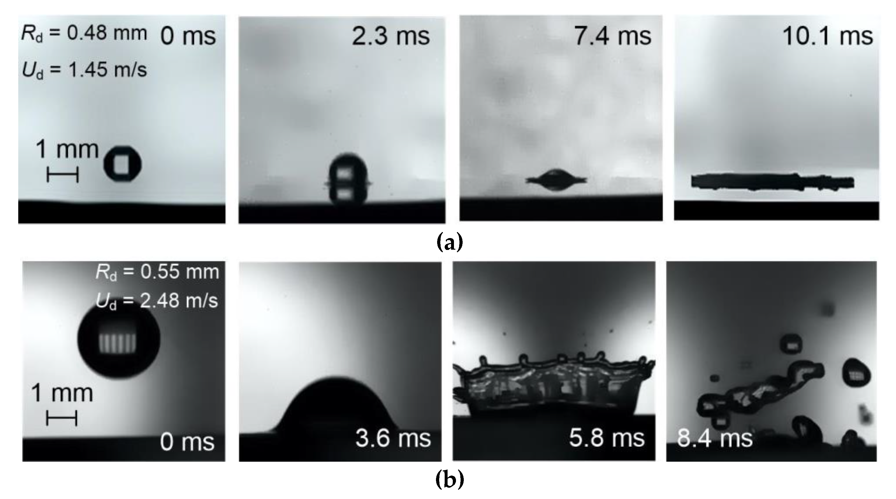
We established that a critical velocity, at which the first drop breaks up after impact, equaled 2.5 m/s (We ≈ 206) for the copper substrate and 2.4 m/s (We ≈ 380) for the aluminum one. If We < 100, the second drop did not break up because it coalesced with the first one or rather with the liquid film on the surface. A wave structure on the liquid film surface did not appear in this case (Figure 2a). With an increase in the Weber number up to 100–150 in the case of the second drop impact on the liquid film of the first drop, the waves emerged but there was no splashing. A further increase in the Weber number caused the resulting film to splash (Figure 2b).
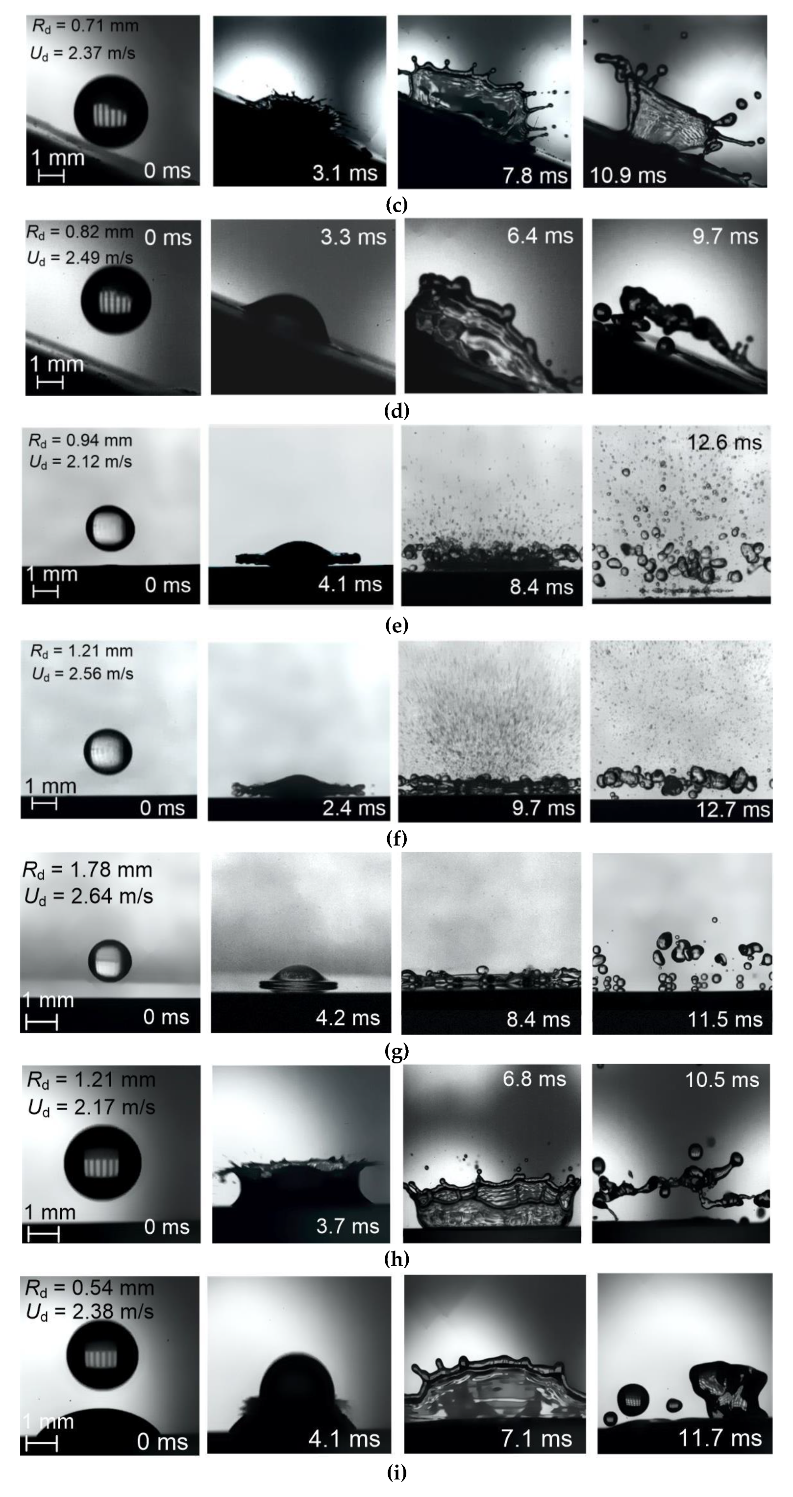
The tests with the copper substrate showed a noticeable increase in the number of child droplets, from about 20 to 30, when changing the impinging angle from about 30° to 60° (Figure 2c). If the angle is reduced to 30°, the number of the child droplets will go down to about 8–10 (Figure 2d).
Having studied the effect of the thermal factor on the impact outcomes, we found out that when the copper substrate was heated up to 50 °C, the drops first spread over the surface. Then, larger child droplets are produced at the solid–liquid interface, and smaller ones (rd ≈ 0.01 mm) emerged at the liquid–gas interface (Figure 2e). The number of child droplets was vast and could reach several dozen. As for rebound, the parent drops were strongly deformed. Only 3–4 fragments with rd ≈ 0.05 mm were detached in this case. With an increase in the wall temperature up to 100 °C, the number of child droplets rose (Figure 2f). A further temperature growth up to 180 °C resulted in mostly large fragments (rd ≈ 0.1 mm) detaching from the parent droplet. Their number approximated 25–40. In general, the drops rebounded from a surface without scattering to the sides, i.e. the spreading angle was considerably limited. In this case, almost no splashing of small child droplets was observed (Figure 2g).
When studying the effect of roughness on outcomes of the impact of the first drop on a surface, we used an aluminum substrate with miscellaneous grades of finish. At the Weber number of We ≈ 380, breakup was the most frequent outcome of the impact of the first drop on a rough surface (Figure 2h). In the case of a smooth surface in the identical impact conditions, the first drop spread over the surface, and each successive one interacted with the resulting liquid film.
Upon impinging on a wall covered by transformer oil, all successively falling drops were observed to coalesce (Figure 2i). The emulsion film formed on the surface caused all the falling droplets to merge into a monolayer. This stems from the fact that the transformer oil enhances the surface tension and interfacial interaction in the liquid. During the impact on the surface covered by paraffin, only very small particles and several larger fragments emerged (Figure 2j). The main part of the drop broke up at the surface and spread over it as separate fragments. This phenomenon could be explained by the high hydrophobicity of paraffin.
During the impact of emulsion drops containing 30 vol.% of transformer oil and 70 vol.% of water, we recorded the phenomena similar to those observed during the impact of water drops on a wall covered by transformer oil (Figure 2k). The oil film prevented the child droplets from spreading over the surface and promoted the coalescence of the falling drops. Sometimes the fragments merged into larger ones and slowly spread over the surface at a short distance from the contact point. On the other hand, after the impact of the castor oil (30 vol.%) in water (70 vol.%) emulsion drops, the number of the child droplets was higher compared with the transformer oil in water emulsion (Figure 2l). Coal (30 wt%)–water (70 wt%) slurry drops broke up more actively than water drops impinging on a surface, i.e. the number of child droplets was noticeably higher (Figure 2m). The presence of solids in the drops cause drop surface instability and intensify their breakup.
One of the important consistent patterns was established when we analyzed the effect of the drop surface geometry upon contact with a wall on the breakup characteristics. In this case, the experiments were performed using smooth substrates and a metal mesh. When a water drop collided with the mesh, the outstretched fragments of cylindrical shape with a maximum longitudinal size of L ≈ 4 mm were produced. The number and dimensions of such fragments considerably differed from those obtained in similar experiments focusing on drops colliding with each other. We established that the surface area of the solid wall should be much greater than the wall–droplet contact area to provide intense breakup. This is because the contact area of the drop grows due to a large number of the falling drops. In this case, it is important to provide for a thin layer of liquid on the surface in order to atomize each of the drops considerably, especially in the case of the low impact velocities, as well as high viscosity and surface tension.
In contrast to the drop–drop collisions [13,14,15,16,17,18], here we distinguished two regimes. In the first regime, the first drop spreads and all the successively impinging drops merge into a liquid layer on the surface. The second regime involves a fine aerosol generated by the drop impact on the wall. When drops collide with each other, four regimes are identified [13,14,15,16,17,18], namely, coalescence, rebound, separation, and breakup. Rebound means that drops approach each other and then move apart without immediate contact because the kinetic energy is not enough for drops to pass across the gas–vapor layer between them. In the separation regime, the number and size of the primary drops as the same as those of the newly formed fragments. Depending on the drop properties, their size and velocity, impingement angle, and heating temperature, the Weber number ranges providing each of the four regimes significantly differed. Therefore, the following Weber number ranges in [13,14,15,16,17,18] can be considered general for the known experimental results on the collision of two drops: 0.5–5 for rebound, 1–20 for coalescence, 15–50 for separation, and 30–100 for breakup. These values considerably differed from the critical ones in the case of a drop impact on a surface [1,2,3,4,5,6,7,8,9,10].

3.2. Effect of a Group of the Governing Parameters

3.2.1. Velocity, Size, and Impinging Angle

Table 4 presents how two key factors defining the inertia force, namely, size and velocity of drops, affected the impact characteristics. We demonstrated the variation ranges of the drop size and velocity, as well as of the Weber number. These ranges corresponded to the two observed regimes—intense breakup or deposition of the drops on a wall and formation of a thin liquid film. In this regard, the results were generalized by the data obtained in all the tests performed with an initial drop size ranging from 0.5 mm to 3 mm. To find the boundary of transition between two impact regimes, the range was divided into four subranges, in particular, 0.5–1 mm, 1–2 mm, 2–2.5 mm, and 2.5–3 mm (Table 4).
The experiments showed that the drop velocity critically affects the transition boundary between deposition and breakup. Table 4 demonstrates that the drop breakup stably occurred when their size ranged from 0.5 to 3 mm and velocity exceeded 2 m/s. The general range of the critical impact velocities is 2–2.5 m/s. It correlates well with findings [19] describing the stable breakup at a velocity of higher than 2.12 m/s.
The snapshots of the tests depicted the common pattern in the range of initial drop sizes of up to 1.5–2 mm: the larger the droplet, the lower impact velocity required for its breakup. As expected, the critical Weber numbers could be attained by increasing the size or velocity of a drop. The contribution of these two parameters was noticeably different. In particular, to produce a greater number of small child droplets, it was necessary to increase the size of the parent drop, but to get the minimum size of the child droplets, it was reasonable to increase the velocity. Therefore, the expected shift of the transition boundary from deposition to breakup occurred with the growth of Rd at lower impact velocities and, consequently, Weber numbers (see Table 4 for the first two ranges of the drop sizes). In the case of large initial drops, we recorded a strong surface deformation that promoted both the reduction and growth of the transient (critical) velocities (Table 4). Large drops most often had a shape of disk or ellipsoid. The disk shape was typical of lower critical velocities but the ellipsoid one required higher impact velocities. The same reasons allowed us to make similar conclusions in terms of the transient critical Weber numbers. Table 4 depicts a wide range of We for the four subranges of the initial sizes, namely, We = 180–420.
Table 4 starkly illustrates the role of the impinging angle in determining the impact regime. The larger the parent drop was, the smaller the impinging angle would be enough for intense secondary atomization. This is largely caused by a high inertia force. A small parent drop could be deposited on a surface if the impinging angle was less than π/3. Therefore, to enhance the drop breakup during the impingement, our recommendation is to utilize an impinging angle ranging from π/3 to π/2. These results extend the numerical and experimental findings by Li and Duan [20] in terms of the drop impact on an inclined wetted surface. In their study [20], the initial temperature of drops equaled 50 °C, and the temperature of the wall was 27 °C. The impinging angle was 30°, and the impact velocity ranged from 1 m/s to 6 m/s. Li and Duan [20] also showed that at low impact velocities, deposition took place; however, at an impact velocity of 6 m/s, a corona emerged. Then, it stably broke up into child droplets.
The map of the wall-drop impact regimes in Figure 3a was plotted by computing the two governing criteria, namely, the Weber and Ohnesorge numbers, accounting for inertia, viscosity, and surface tension. Thus, when plotting this map, we did not consider the impinging angles and substrate characteristics. This is the main reason for a noticeable scattering of the experimental Oh and We numbers. Nevertheless, when generalizing the experimental findings, we were able to clearly highlight the boundaries of transition from the first impact regime to the second one. In addition, the wide variation range of the drop size played an instrumental role in plotting the map We(Oh). Overall, the scattering of the points looks quite predictable and exhibits the dominance of the conditions for the intense breakup with the growth of We and Oh, i.e. when inertial and viscous forces exceed surface tension.
Figure 3b,c clearly demonstrate the differences in S1/S0 and size distributions of child droplets accounting for the initial parent drop sizes. The differences were noticeable at We < 250 and could reach 30–40%. This result illustrates wide possibilities for varying the drop size and velocity as well as surface tension at We < 250 to provide for the required breakup characteristics. The common pattern suggests that the smaller the initial parent drop, the smaller child droplets it will produce. However, the larger the parent drop, the more child droplets produced, in general. The impact velocity is also essential when defining the impact regime. Figure 4 more clearly demonstrates the transition between deposition and breakup using the dimensionless angular parameter of impact. The same conclusion applies to the S1/S0(We) function. The higher the impinging angle was, the lower impact velocities and the smaller drop size were needed for the stable breakup resulting in small child droplets. This is because of growing inertial, frictional and drag forces. The size distributions of child droplets in Figure 4c showed that a transition to the so-called normal distribution was only possible with large initial sizes of the parent drops. With small initial sizes, the number of small child droplets was higher. Thus, the higher the Weber number, the more noticeable these trends.

3.2.2. Wall Heating

The experiments revealed that the largest number of child droplets was attained by the impact on a heated surface. We figured out the temperature range, namely from 50 °C to 100 °C, at which the thermal factor had a significant influence. To explain the experimental results in Figure 5, we have the following assumptions to add to the findings [6,8]. First, due to wall heating, a preheated liquid layer was formed at the surface after the first drop fell. This decreased the surface tension and weakened the intermolecular bonds. Consequently, the surface layers and successively falling drops broke up more actively. Second, when the wall was heated above 100 °C, a vapor–gas buffer zone was produced between the parent drop and the wall. It reduced the heat flux from the wall to the liquid due to lower thermal diffusivity of liquid in comparison with the wall material. As a result, the heating of the near-surface layer became less intense. Therefore, the wall heating could not intensify the liquid heating at temperatures above a certain limit. Instead of this, we observed a weaker breakup of parent drops and reduced number of child droplets. Third, when parent drops contacted the wall heated up from 20 °C to 100 °C, water reached its boiling point, which led to the micro-explosion of parent drops. This was the reason for the noticeable growth of small child droplets and the S1/S0 ratio, as shown in Figure 5. However, the size distribution of child droplets was quite uniform. Fourth, the wall heating could have a marked effect on breakup by way of rebound of the newly emerged child droplets. They evaporated because of heating, and a vapor buffer zone was generated around them, which prevented coalescence with other falling drops. In this case, breakup could occur during the collision of heated liquid fragments with either colder or warmer child droplets. The higher the temperature of the liquid fragments, the lower their viscosity and surface tension. This enhanced the further breakup of secondary droplets.

3.2.3. Wall Material

Figure 6 shows how the impact regimes vary if we use a fine-meshed screen and a substrate made of various materials. Based on experimental results [6,7,8,9], we formulated an assumption that the fine-meshed screen allowed an increase in the number of small child droplets. When a drop impinged on the screen, dumbbell-shaped child droplets emerged. The liquid surface area grew by 2.2 times (Figure 6b). However, the impact on a solid surface could provide better drop atomization at the same We. In particular, if the screen is used, the size of child droplets could reach 350–500 μm (Figure 6c). If the cellular construction size is assumed even smaller, the falling drop will disintegrate more slowly and into larger fragments because the pressure will be insufficient to squeeze the liquid out of the mesh.
During the impact on a surface, the kinetic energy of a drop mainly defined the breakup characteristics, namely the number and size of child droplets. If the surface was smooth, then the contact area would be minimum during the impact. However, if the surface was rough, then the surface area of a drop would considerably increase during impact. In particular, we managed to provide for the growth of this parameter by two to three times. In this case, the friction force acting upon the drop impinging on a rough surface also grew. As a result, the kinetic energy of the drop impinging on a smooth surface was used to break it up. In the case of a rough surface, a part of the kinetic energy dissipated due to friction. Moreover, when the surface was extremely rough, i.e., in the case of the screen, the vertical elements of such a surface prevented the breakup. A part of the drop passing through a cell could not transform in the cross direction. Besides, the top of the drop could disintegrate as much as it protruded from the mesh cell.
When comparing the breakup characteristics of the drops contacting with copper, steel, and glass surfaces, we established the distributions depicted in Figure 6c. For the metal surfaces, the distributions were quite close in terms of character and size, but the contact with a glass surface mostly produced small child droplets. However, the liquid surface area grew more noticeably when we used metal substrates (Figure 6b). The higher the Weber number, the more noticeable these patterns. This could be explained by a considerable difference in heat fluxes from the wall to the approaching droplet. For the metal substrates, these heat fluxes were notably higher due to higher thermal conductivity and diffusivity compared to glass. The higher the heat flux, the more intensely a drop broke up.

3.2.4. Surface Roughness and Hydrophilicity

Figure 7 and Figure 8 demonstrate that surface roughness and hydrophilicity may considerably affect not only the threshold drop velocity and size but also the number and size of child droplets. In contrast to the previous governing factor (Figure 6), Figure 7 and Figure 8 show that the S1/S0 ratio and the number of child droplets could increase by 2–6 times.
The experimental results in Figure 7c gave grounds for other conclusions. The functions N(rd) demonstrated that the surface roughness noticeably affected the number of child droplets when parent drops were small. When parent drops were comparable in size with the roughness cell, the number and size of child droplets were the same as for the impact on a smooth surface. If the cross dimension of the drop was smaller than size of the roughness cell, then the inner of the roughness cell did not affect the drop behavior. When impinging on a roughness cell, the drop broke up in the same way as during the impact on a smooth surface. In other cases, roughness did affect the characteristics of child droplets. If the parent drop partially falls into a roughness cell and partially on the edge of a roughness element, the drop interacts with the surface in the same way as with a metal mesh.
According to Figure 8, the higher the hydrophobicity of the wall surface, the more intensely the parent drop broke up. For the hydrophilic surfaces, even heated up to high temperatures, rebound or deposition occurred. As for hydrophobicity, it could be provided in different ways. Unnikrishnan et al. [21] studied how the chemical treatment of a metal surface affects the behavior of impinging drops. During the impact on a hydrophobic etched surface, a drop splashed and a corona was formed. Negeed et al. [22] demonstrated a 10 % increase in the maximum spreading diameter of a drop over a super-hydrophilic surface heated up to 300 °C, i.e., from 30% to 40% relative to the initial diameter of a drop, as compared with the case of the drop impact on an unheated surface. During the experiments with a large group of drops impinging on such surfaces, we established some patterns. In particular, it is more efficient to enlarge the contact area of drops with such surfaces in order to increase S1/S0. However, to enlarge a number of small child droplets, We should be increased.

3.2.5. Drop Homogeneity and Heterogeneity; Liquid Viscosity and Surface Tension

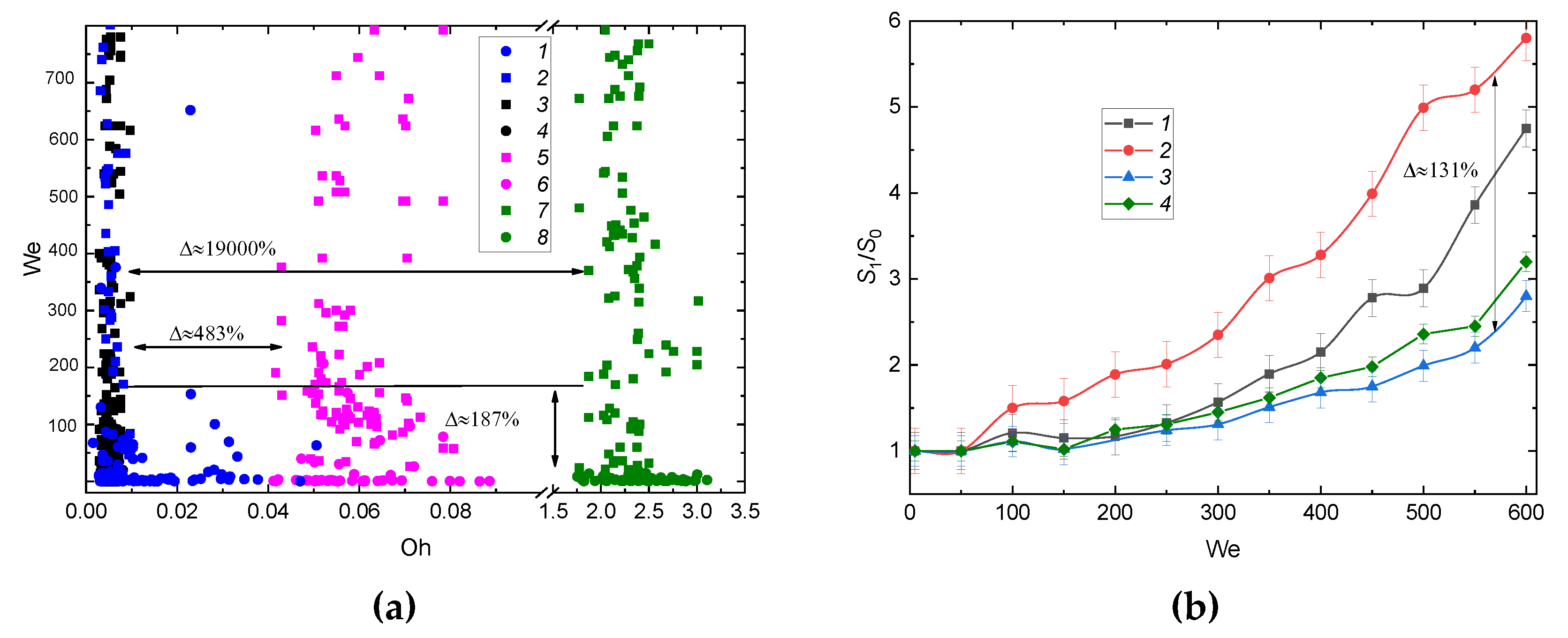
Figure 9 and Figure 10 show that the rheological properties of the components could noticeably change the correlations of the forces of inertia, surface tension, and viscosity on the regime maps. In particular, the critical (transient) Reynolds, Weber, and Ohnesorge numbers, corresponding to the transition from deposition and coalescence to breakup, differed by 1.5–3 times. Such differences could be regarded as significant. The impingement of slurry drops varied especially widely. In this case, the differences in the number and size of child droplets as well as in the critical Re, We, and Oh numbers could be more than tenfold. This resulted from the sedimentation of solids in a drop and their impact on a solid surface, elevated viscosity of the composition and accelerated production of child droplets when the parent drop contacted with a wall.
Figure 10 compares the results for the homogeneous and multi-component drops. We note the most significant increase in the number of large child droplets if the drops of high-viscous slurries and emulsions impinged on the wall. Solids and liquid admixtures with a low surface tension considerably weakened the intermolecular bonds both in the near-surface layer and inside the falling drops. Therefore, the drops were deformed greatly when moving and impinging on the wall. Significant deviations of the drop shape from a spherical one, i.e., disk, dumbbell, and ellipsoid shapes, were recorded precisely in the case of the multi-component drops. As known, the drag force grows considerably in the case of such drop shapes. This resulted in the drop fragmentation even before their impact on a surface.
Figure 10 shows that the main impact characteristics of water and emulsion drops are quite close. However, in the case of emulsion drops, the number of emerging large child droplets increased much more significantly due to lower surface tension. Moreover, due to the high viscosity of emulsions, child droplets rapidly took the spherical shape in contrast to the experiments with water drops, in which the emerging fragments were mainly of the ellipsoidal shape.
The largest number of child droplets and their lower size were provided in the experiments with slurry drops. For such drops, the growth in the number of child droplets was conditioned by the surface instability due to the heterogeneous composition and different densities of the components.
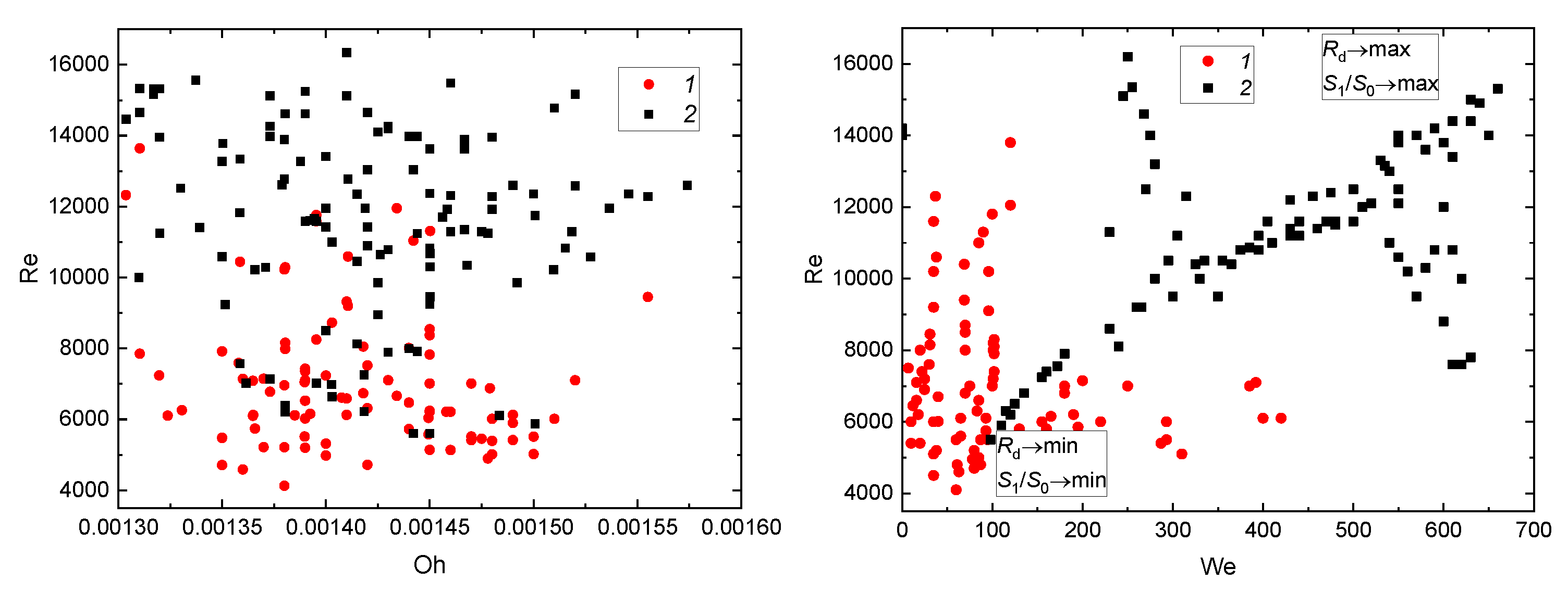
Figure 9 illustrates the deposition-to-breakup transition in the form of the Re(We) map. In contrast to the Re(Oh) function, by using the Re(We) map we managed to show more clearly the relationship between viscosity and surface tension. The experimental results correlated well with the research findings by Roisman et al. [23], in which the fundamental patterns and critical conditions for drop deposition and drop rebound were defined.

3.3. Prospects of the Drop Breakup When Impacting onto a Surface

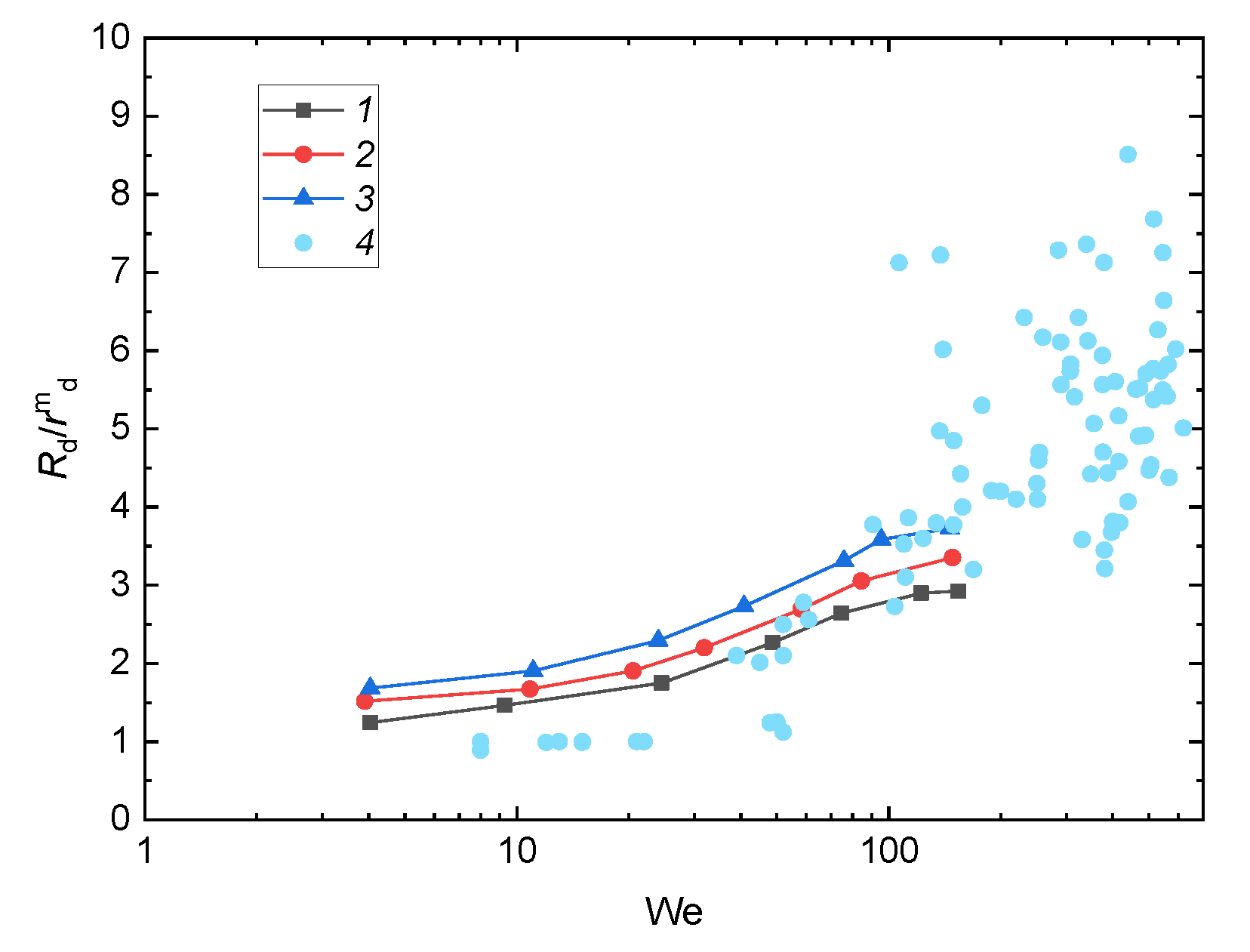
Figure 11 illustrates the comparison between the experimental data and the results of studies [8,9,10] as the relative liquid surface area versus the Weber number. With an increase in the Weber number, the maximum size of a child droplet grew. This was because the increase in the number of secondary droplets resulted in higher inertia, which resisted the surface tension force. Finally, this led to a longer spreading time of a drop over the surface. The characteristics obtained by other researchers [8,9,10] differ from those presented in this study by 8% to 32%. This result illustrates the importance of further research of the drop impact on a wall in terms of developing a more informative dimensionless criterion, which would account for not only inertia and surface tension but also other factors markedly affecting the impingement characteristics. This will make it possible to develop comprehensive regime maps with an account of all the governing characteristics, namely, dimensions, temperature, thermophysical properties of a material, hydrophilicity, hydrophobicity, roughness, etc. To date, this task has not been solved and it remains urgent for the global scientific community.
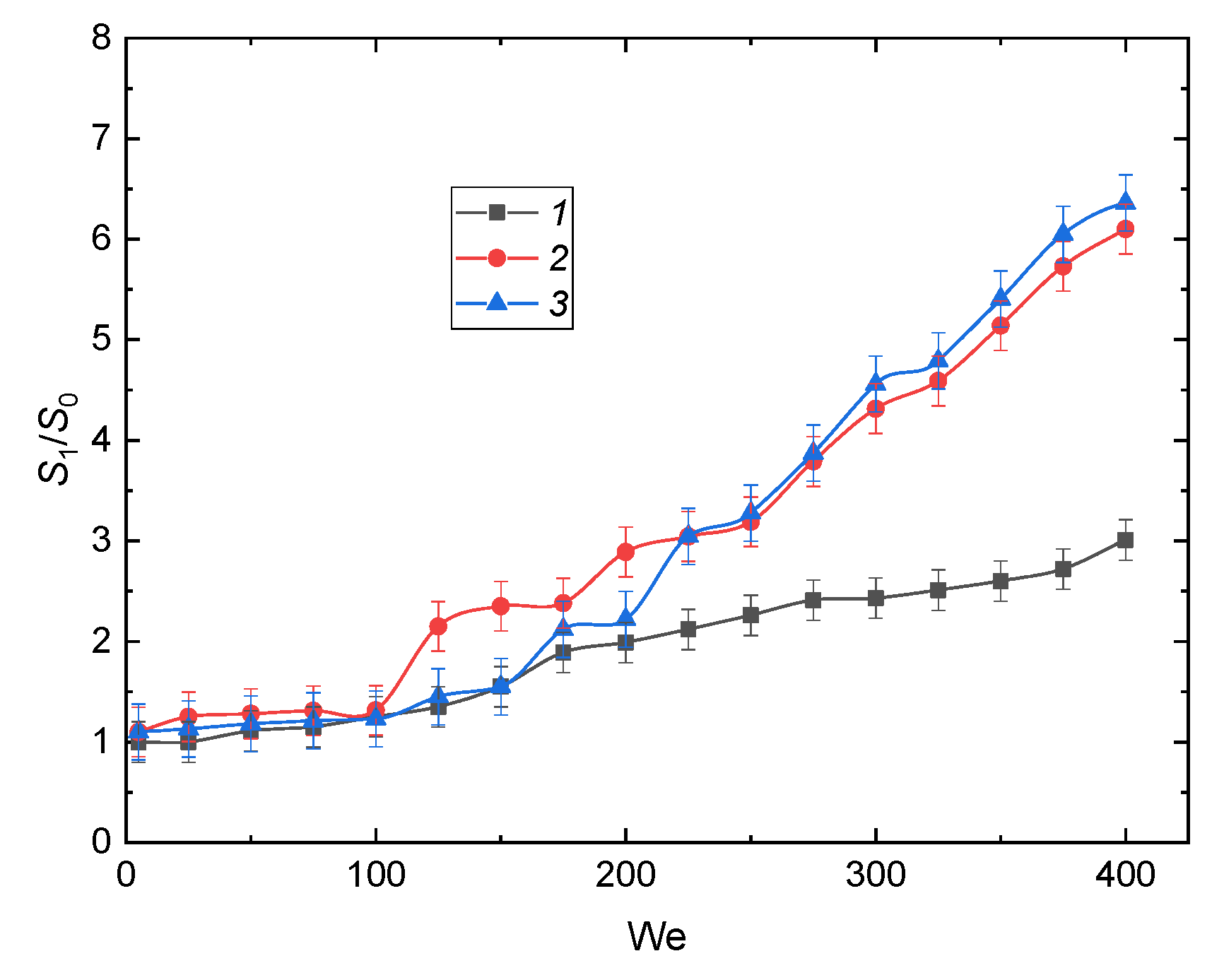
We can conclude that the dispersion of the ratios Rd/rmd noticeably increases with the growing Weber number (Figure 11). For the total surface area of the liquid, we got moderate confidence intervals even at high Weber numbers (Figure 12). This was because an increase in the inertial force led to a noticeable deformation of the drop surface. The contact area strongly depended on the drop shape. In particular, the contact area was the highest with disk-shape drops, the lowest for vertical ellipsoids, and moderate for spheres. The larger the contact area, the thinner the film at the surface. At high impact velocities, this film broke up into a large number of smaller secondary droplets. This was especially noticeable when disk-shaped drops impinged on a wall. In the case of spheres and ellipsoids, the number of larger secondary droplets considerably increased because of the smaller contact area and higher thickness of the liquid film on the surface. A moving drop rotated about its center of mass, so it could take various shapes directly before impact. That is why the dispersion of the experimental values in Figure 11 was quite noticeable. However, the differences in the mean size of child droplets were not that large. Therefore, the ratio S1/S0 grew with an increase of the Weber number more monotonously (Figure 12).
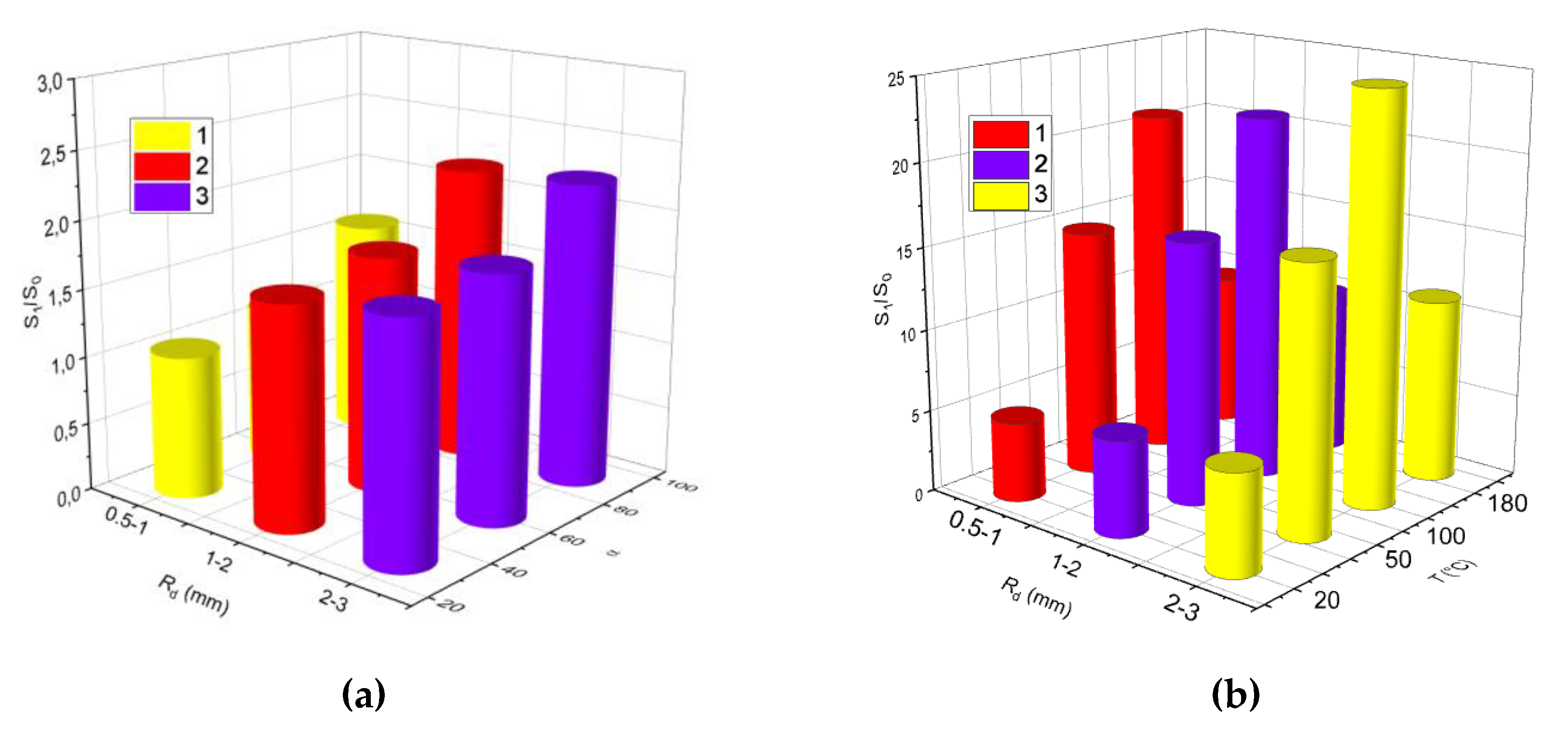
Figure 11 illustrates significant differences in the ratios S1/S0 in the case of impinging drops with different initial volumes. In particular, we performed experiments with a single large drop and three smaller ones. The total volume of the three drops equaled that of the single one. The growth of S1/S0 in the tests with three drops was noticeably higher. Thus, a pre-breakup and further impact on a wall could provide a strong increase in S1/S0. If we compare S1/S0 in the experiments with two or three drops of equal size, the number of the parent drops was of no importance when We exceeded 200 (see Figure 12). Thus, only the size of each drop and, consequently, its volume plays an important role. This result indicates that the experimental findings can be used to predict the breakup of a group of drops and even aerosols. When the Weber number was lower than 200, both the initial volume and number of drops played an important role (Figure 13) because the inertial force did not dominate as much as the surface tension and viscosity. In such conditions, the primary and secondary atomization systems [24,25,26] will be more difficult to adjust because S1/S0 will change considerably if almost any of the aerosol parameters is varied. By using a group of the parameters, namely, size, velocity, and drop concentration in a gaseous environment, we could increase the liquid surface area could by 2–25 times after impingement (Figure 13).

4. Conclusions

The novelty of the study lies in evaluating the effect of a group of the main factors on the breakup of the primary drops impinging on the heated wall and defining the conditions for producing a fine aerosol. These factors include the drop velocity and size, Weber number, impingement angle, wall temperature and heat fluxes, thermophysical properties of the wall material, surface roughness, hydrophobicity, and hydrophilicity, homogeneity and heterogeneity of drops, liquid viscosity and surface tension, as well as the effect of several drops falling successively. The research findings can be used to predict the conditions for increasing the liquid surface area several times, i.e. to provide an efficient secondary breakup, hence the practical significance. In particular, when studying the contribution of each factor, it is important to compare the ratios S1/S0. The critical velocity for breakup was 2–2.5 m/s. Over a range of the drop sizes from 2 mm to 2.7 mm, the highest S1/S0 was 3.51. By changing the impingement angle, it is possible to reach S1/S0 equal to 3.48. The impingement angles of αd = 60–90° provided the maximum S1/S0. A noticeable increase in the number of secondary droplets and the ratio S1/S0 could also be achieved by heating the surface. We determined a several-fold growth of S1/S0 with an increase in the surface temperature. The maximum S1/S0 equal to 24.92 was obtained at a surface temperature of T ≈ 100 °C. We demonstrated the effect of the surface material on the size distributions of secondary droplets and the ratios S1/S0. The utilization of metal substrates allowed us to increase S1/S0 up to 3.8. Then, different roughness of surfaces also resulted in changing S1/S0. In this case, the maximum value was 6.55. Moreover, the drop breakup intensity considerably depended on the drop composition. Thus, for the slurry containing 30 wt% of coal and 70 wt% of water, S1/S0 grew up to 5.78, and, consequently, the number of small secondary droplets increased. The analysis of the above-mentioned factors enabled us to predict the growth of S1/S0 by dozens of times in the case of their combined usage.

Author Contributions

Investigation, A.V.D., S.S.K., N.E.S.; writing—review and editing, O.V.V., S.S.K., M.V.P. All authors have read and agreed to the published version of the manuscript.

Funding

This research was funded by Russian Science Foundation grant number [18–71–10002].

Acknowledgments

The research was supported by the Russian Science Foundation (project 18–71–10002).

Conflicts of Interest

The authors declare no conflict of interest.

References

  1. Liang, G.; Mudawar, I. Review of drop impact on heated walls. Int. J. Heat Mass Transf. 2017, 106, 103–126. [Google Scholar] [CrossRef]
  2. Liang, G.; Mudawar, I. Review of mass and momentum interactions during drop impact on a liquid film. Int. J. Heat Mass Transf. 2016, 101, 577–599. [Google Scholar] [CrossRef]
  3. Šikalo, Š.; Marengo, M.; Tropea, C.; Ganić, E.N. Analysis of impact of droplets on horizontal surfaces. Exp. Therm. Fluid Sci. 2002, 25, 503–510. [Google Scholar] [CrossRef]
  4. Xie, J.; Wong, T.N.; Duan, F. Modelling on the dynamics of droplet impingement and bubble boiling in spray cooling. Int. J. Therm. Sci. 2016, 104, 469–479. [Google Scholar] [CrossRef]
  5. Tang, C.; Qin, M.; Weng, X.; Zhang, X.; Zhang, P.; Li, J.; Huang, Z. Dynamics of droplet impact on solid surface with different roughness. Int. J. Multiph. Flow 2017, 96, 56–69. [Google Scholar] [CrossRef]
  6. Clavijo, C.E.; Crockett, J.; Maynes, D. Hydrodynamics of droplet impingement on hot surfaces of varying wettability. Int. J. Heat Mass Transf. 2017, 108, 1714–1726. [Google Scholar] [CrossRef] [Green Version]
  7. Fujimoto, H.; Tong, A.Y.; Takuda, H. Interaction phenomena of two water droplets successively impacting onto a solid surface. Int. J. Therm. Sci. 2008, 47, 229–236. [Google Scholar] [CrossRef]
  8. Negeed, E.-S.R.; Ishihara, N.; Tagashira, K.; Hidaka, S.; Kohno, M.; Takata, Y. Experimental study on the effect of surface conditions on evaporation of sprayed liquid droplet. Int. J. Therm. Sci. 2010, 49, 2250–2271. [Google Scholar] [CrossRef]
  9. Senda, J.; Kanda, T.; Al-Roub, M.; Farrell, P.V.; Fukami, T.; Fujimoto, H. Modeling Spray Impingement Considering Fuel Film Formation on the Wall. SAE Tech. Pap. 1997. [Google Scholar] [CrossRef]
  10. Roisman, I. Inertia dominated drop collisions. II. An analytical solution of the Navier–Stokes equations for a spreading viscous film. Phys. Fluids 2009, 21, 52104. [Google Scholar] [CrossRef]
  11. Williams, Y.O.; Roas-Escalona, N.; Rodríguez-Lopez, G.; Villa-Torrealba, A.; Toro-Mendoza, J. Modeling droplet coalescence kinetics in microfluidic devices using population balances. Chem. Eng. Sci. 2019, 201, 475–483. [Google Scholar] [CrossRef]
  12. Lunkenheimer, K.; Wantke, K.D. On the applicability of the du Nouy (ring) tensiometer method for the determination of surface tensions of surfactant solutions. J. Colloid Interface Sci. 1978, 66, 579–581. [Google Scholar] [CrossRef]
  13. Orme, M. Experiments on droplet collisions, bounce, coalescence and disruption. Prog. Energy Combust. Sci. 1997, 23, 65–79. [Google Scholar] [CrossRef]
  14. Krishnan, K.G.; Loth, E. Effects of gas and droplet characteristics on drop-drop collision outcome regimes. Int. J. Multiph. Flow 2015, 77, 171–186. [Google Scholar] [CrossRef]
  15. Pawar, S.K.; Henrikson, F.; Finotello, G.; Padding, J.T.; Deen, N.G.; Jongsma, A.; Innings, F.; Kuipers, J.A.M.H. An experimental study of droplet-particle collisions. Powder Technol. 2016, 300, 157–163. [Google Scholar] [CrossRef] [Green Version]
  16. Wang, Y.; Gratadeix, A.; Do-Quang, M.; Amberg, G. Events and conditions in droplet impact: A phase field prediction. Int. J. Multiph. Flow 2016, 87, 54–65. [Google Scholar] [CrossRef]
  17. Charalampous, G.; Hardalupas, Y. Collisions of droplets on spherical particles. Phys. Fluids 2017, 29, 103305. [Google Scholar] [CrossRef] [Green Version]
  18. Finotello, G.; De, S.; Vrouwenvelder, J.C.R.; Padding, J.T.; Buist, K.A.; Jongsma, A.; Innings, F.; Kuipers, J.A.M. Experimental investigation of non-Newtonian droplet collisions: The role of extensional viscosity. Exp. Fluids 2018, 59, 113. [Google Scholar] [CrossRef] [Green Version]
  19. Lin, S.; Zhao, B.; Zou, S.; Guo, J.; Wei, Z.; Chen, L. Impact of viscous droplets on different wettable surfaces: Impact phenomena, the maximum spreading factor, spreading time and post-impact oscillation. J. Colloid Interface Sci. 2018, 516, 86–97. [Google Scholar] [CrossRef]
  20. Li, D.; Duan, X. Numerical analysis of droplet impact and heat transfer on an inclined wet surface. Int. J. Heat Mass Transf. 2019, 128, 459–468. [Google Scholar] [CrossRef]
  21. Unnikrishnan, P.K.; Vaikuntanathan, V.; Sivakumar, D. Impact dynamics of high Weber number drops on chemically modified metallic surfaces. Colloids Surfaces A Physicochem. Eng. Asp. 2014, 459, 109–119. [Google Scholar] [CrossRef]
  22. Negeed, E.-S.R.; Albeirutty, M.; Takata, Y. Dynamic behavior of micrometric single water droplets impacting onto heated surfaces with TiO2 hydrophilic coating. Int. J. Therm. Sci. 2014, 79, 1–17. [Google Scholar] [CrossRef]
  23. Roisman, I.V.; Breitenbach, J.; Tropea, C. Thermal atomisation of a liquid drop after impact onto a hot substrate. J. Fluid Mech. 2018, 842, 87–101. [Google Scholar] [CrossRef]
  24. Solomatin, Y.; Shlegel, N.; Strizhak, P. Secondary atomization of firefighting liquid droplets by their collisions. At. Sprays 2019, 29, 429–454. [Google Scholar] [CrossRef]
  25. Kuznetsov, G.V.; Shlegel, N.E.; Solomatin, Y.; Strizhak, P.A. Combined techniques of secondary atomization of multi-component droplets. Chem. Eng. Sci. 2019, 209, 115199. [Google Scholar] [CrossRef]
  26. Solomatin, Y.; Shlegel, N.E.; Strizhak, P.A. Atomization of promising multicomponent fuel droplets by their collisions. Fuel 2019, 255, 115751. [Google Scholar] [CrossRef]
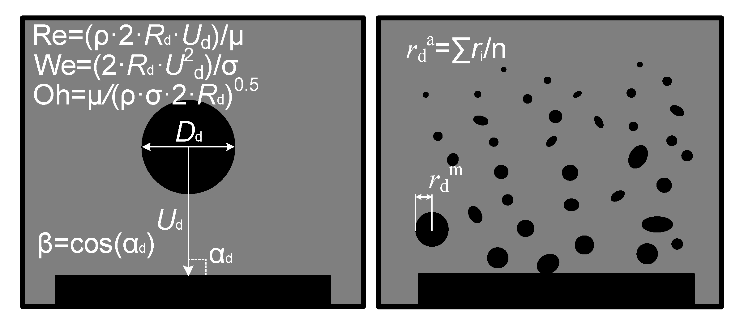
Figure 1. Diagram of the drop impingement and the main recorded and calculated parameters.
Applsci 10 00942 g001
Figure 2. Snapshots of the drop impact on the wall: (a) water; (b) water; (c) water, impingement angle αd ≈ 60°; (d) water, impingement angle αd ≈ 30°; (e) water, surface with a temperature of T ≈ 50 °C; (f) water, surface with a temperature of T ≈ 100 °C; (g) water, surface with a temperature of T ≈ 180 °C; (h) metal surface (Ra = 20; 16; 10 μm; Rz = 80; 63; 50; 40 μm); (i) water, surface is covered by the transformer oil; (j) water, surface is covered by paraffin; (k) emulsion (30 vol.% of the transformer oil, 70 vol.% of water); (l) emulsion (30 vol.% of the castor oil, 70 vol.% of water); (m) slurry (30 wt% of coal, 70 wt% of water).
Applsci 10 00942 g002aApplsci 10 00942 g002bApplsci 10 00942 g002c
Figure 3. (a) Regime map of the drop impact on the surface as a function of We(Oh): 1—deposition of the first drop and coalescence with all others; 2—breakup; (b) S1/S0(We); (c) size distribution of the child droplets at We = 200 and with different sizes of the parent drop: 1Rd = 2–2.7 mm; 2Rd = 1–2 mm; 3Rd = 0.5–1 mm.
Applsci 10 00942 g003
Figure 4. (a) Regime map of the drop impact accounting for the angular parameter and Weber number: 1—deposition of the first drop and coalescence with all others; 2—breakup; (b) S1/S0(We); (c) size distribution of child droplets at We=200 and at different impingement angles: 1—αd = 0–30°; 2—αd = 30–60°; 3—αd = 60–90°.
Applsci 10 00942 g004
Figure 5. (a) Regime map of the drop impact on the wall (circle—deposition of the first drop and coalescence with all others, square—breakup) as a function of We(Oh): 1,2T ≈ 20 °C; 3,4T ≈ 50 °C; 5,6T ≈ 100 °C; 7,8T ≈ 180 °C; (b) S1/S0(We); (c) size distribution of child droplets at We = 200 and at different wall temperatures: 1T ≈ 20 °C; 2T ≈ 50 °C; 3T ≈ 100 °C; 4T ≈ 180 °C.
Applsci 10 00942 g005
Figure 6. (a) Regime map of the drop impact on the wall (circle—deposition of the first drop and coalescence with all others, square—breakup) as a function of We(Oh) at a wall temperature of about 100 °C: 1, 2—copper surface; 3, 4—steel surface; 5, 6—glass surface; 7, 8—metal mesh; (b) S1/S0(We); (c) size distribution of child droplets at We = 200 and at different wall configurations: 1—copper surface; 2—steel surface; 3—glass surface; 4—metal mesh.
Applsci 10 00942 g006
Figure 7. (a) Regime map of the drop impact on the wall (circle—deposition of the first drop and coalescence with all others, square—breakup) as a function of We(Oh): 1, 2Ra = 0.01; 0.008 μm; Rz = 0.05; 0.04; 0.032 μm; 3, 4Ra = 2.5; 1.25 μm; Rz = 10; 8; 6.3 μm; 5, 6Ra = 20; 16;10 μm; Rz = 80; 63; 50; 40 μm; (b) S1/S0(We); (c) size distribution of child droplets at different surface roughness: 1Ra = 0.01; 0.008 μm; Rz = 0.05; 0.04; 0.032 μm; 2Ra = 2.5; 1.25 μm; Rz = 10; 8; 6.3 μm; 3Ra = 20; 16;10 μm; Rz = 80; 63; 50; 40 μm; 4—smooth surface.
Applsci 10 00942 g007
Figure 8. (a) Regime map of the drop impact on the wall (circle—deposition of the first drop and coalescence with all others, square—breakup) as a function of We(Oh): 1,2—copper surface; 3,4—surface covered by paraffin; 5,6—surface covered by oil; (b) S1/S0(We); (c) size distribution of child droplets at We = 200 and at different wetting properties of a surface: 1—copper surface; 2—surface covered by paraffin; 3—surface covered by oil.
Applsci 10 00942 g008
Figure 9. Regime maps of the drop impact as functions of Re(Oh) and Re(We): 1—deposition of the first drop and coalescence with all others, 2—breakup.
Applsci 10 00942 g009
Figure 10. (a) Regime map of the drop impact on the wall (circle—deposition of the first drop and coalescence with all others, square—breakup) as a function of We(Oh): 1,2—water; 3,4—slurry (30 wt% of coal, 70 wt% of water); 5,6—emulsion (30 vol.% of transformer oil, 70 vol.% of water); 7,8—emulsion (30 vol.% of castor oil, 70 vol.% of water); (b) S1/S0(We); (c) size distribution of child droplets at We = 200: 1—water; 2—slurry (30 wt% of coal, 70 wt% of water); 3—emulsion (30 vol.% of transformer oil, 70 vol.% of water); 4—emulsion (30 vol.% of castor oil, 70 vol.% of water).
Applsci 10 00942 g010aApplsci 10 00942 g010b
Figure 11. Ratio between the initial drop radius and maximum radius of secondary droplets vs. We: 1—[8]; 2—[9]; 3—[10]; 4—experimental data for water.
Applsci 10 00942 g011
Figure 12. Comparison of breakup characteristics of a single drop and a group of smaller droplets impinging on a surface as a function of S1/S0(We): 1—single drop (V0 ≈ 600 μL), 2—three drops (V0 ≈ 200 μL for each one), 3—two drops (V0 ≈ 200 μL for each one).
Applsci 10 00942 g012
Figure 13. S1/S0 vs. Rd vs. ɑd (a); S1/S0 vs. Rd vs. T (b): 1Rd = 0.5–1 mm; 2Rd = 1–2 mm; 3Rd = 2–3 mm.
Applsci 10 00942 g013
Table 1. Properties of the liquids under study.
Liquid (Volume or Mass Concentrations of the Admixtures to Water)Temperature [°C]Density [kg/m3]Surface Tension [N/m]Dynamic Viscosity [Pa∙s]
Water209980.07260.0014
Coal slurry (30 wt%)2011260.24720.0033
Transformer oil emulsion (30 vol%)209630.05670.0069
Castor oil emulsion (30 vol%)209870.06150.2857
Table 2. Recorded and calculated parameters of the drop impact.
CompositionWaterWater Water
No. of impingement12 546
αd—impingement angle [°]91.289.430.1
Rd—drop radius [mm]2.52.22.6
Ud—drop velocity [m/s]1.32.32.6
Impact outcomespreadingbreakupbreakup
No. of frame5412614568
Drop shapespherespheresphere
N—number of child droplets15013
We·[(2·Rd·Ud^2)/σ126.3341.7508
Oh·[μ/(ρ·σ·2·Rd)^1/20.00130.00150.0013
Re [(ρ·2·Rd·Ud)/μ6776.910,433.513,867.8
β·[cos(ɑd)]0.020.010.87
rda—mean diameter of child droplets0.050.23
S0—surface area of the parent drop [mm2]79.166.385.6
Sf—surface area of the liquid film [mm2]79.157.6 76.4
S—surface area of child droplets [mm2]105.3121.3
S1—total surface area of child droplets and liquid film [mm2]79.1162.9 197.7
S1/S012.42.3
Table 3. Systematic and random errors in determining the parameters.
ParameterSystematic Error [%]Random Error [%]
Rd1.62.1
Ud2.13.4
αd2.33.1
Table 4. Threshold velocities, impingement angles, and Weber numbers sufficient for drop breakup when impinging on the wall.
Rd [mm]Weber NumbersThreshold Velocities [m/s]Impingement Angles
DepositionBreakupDepositionBreakupDepositionBreakup
0.5–10–195195–6300–2.282.28–30–π/3π/3–π/2
1–20–163163–6300–2.142.14–30–π/4π/4–π/2
2–2.50–442442–6300–2.512.51–30–π/5π/5–π/2
2.5–30–300300–6300–1.891.89–30–π/8π/8–π/2