Abstract
Telemanipulation systems have been widely utilized in industrial, surgical, educational, and even military fields. One of the important issues is that when a robot interacts with environment or objects, it can damage the robot itself or the objects due to hard contact. To address this problem, we propose a novel compliance control of a slave robot using the electromyography (EMG) signal, which is measured by the sensors attached onto the master operator’s arm. The EMG signal is used since it is easy to process and it provides humans with an intuitive capability to perform the operational work. Furthermore, it has been proved that the EMG signal is useful in the control of the stiffness of the slave robot. This research identifies the muscle that is the best suitable to a precision-grip operation, and a series of experiments were performed. A compliance control algorithm with a variable stiffness of a slave robot is proposed, where the stiffness is changed based on the EMG signal, and it is confirmed by a series of experiments using a two-channel force/position teleoperation architecture.
1. Introduction
Telemanipulation systems have been used for diverse purposes [1,2,3]. Over the decades, research studies related to the industrial and surgical fields have been intensively conducted [4,5]. In the industrial field, there are two different applications of telemanipulation systems. For the first one, the manipulator is in contact with the environment, for example, in the task of grinding some material and the task of assembling multiple parts. In the other type, the manipulator moves in a free space with pre-planned trajectory, and thus there is no contact with the environment while following the trajectory. In this case, the manipulator is usually controlled with high stiffness to satisfy the high performance in the position control. Even with a precise position control of the high-stiffness manipulator, the vibration between the manipulator and the environment may exist because a huge reaction force can be generated with even a slight error in the control-loop. This situation can lead to an operational failure and damage the manipulator or the environment. To deal with these problems, various force-control methods regarding the manipulator have been proposed [6].
The typical torque control methods of the manipulators include an impedance control and a hybrid force/position control. The impedance control modulates the mechanical impedance of the end-effector that is in contact with the environment [7,8]. In this method, due to the fixed stiffness, the manipulator may still be damaged by the vibration, and several research studies were conducted to address this problem [9,10]. For the safety of human-robot cooperation in heavy industrial applications, Roveda et al. proposed cooperative fuzzy impedance control with safety rules. To optimize the performance of heavy tasks through human safety-based empowerment, minimal muscle activity using EMG sensors was used to assess the performance cooperation between the human and robot [11]. Roveda et al. introduced a manual guidance controller with force tracking requirements which allows the human operator to perform both fine and large positioning of the robot system to improve the human capabilities while executing cooperative industrial tasks [12]. The hybrid force/position control methods are applied in a situation where the contact force and the fixed position control must be executed simultaneously; that is, the condition where both controls have to avoid operating at the same axis must be satisfied. The hybrid position/force control scheme, which is another method for impedance control, uses two independent control loops of force and position. However, when position control and force control for the same axis are required, position or force control is switched and utilized because it causes errors in position or force [9]. The position control axis and the force control axis are separated and controlled according to the characteristics of the work given in advance. However, it is not suitable for the case where the work is performed in an unspecified environment, like most remote-control operations. For this reason, this method is inappropriate for the uncertain situations. The impedance control was selected for use in this paper as a result. To deal with the fixed stiffness issue of the impedance control, this paper proposes a compliance-control method for which the impedance value of the slave robot is modified in the teleoperation with the electromyography (EMG)-attached to operator’s arm.
A medical wearable robot is the main focus of the method that modifies the robot stiffness using the EMG [13]. From the literature review, the entire manipulator can be controlled with the EMG. Vogel et al. [14] introduced the possibility of controlling the manipulator with only the EMG signal without the modeling of the human arm; however, this control method is disadvantageous regarding the learning procedure and can only be used at low speeds [15]. Lenzi et al. proposed human-robot interface that uses EMG signals to observe users’ movement intention assisted by the exoskeleton, reducing their muscle effort while maintaining the joint trajectory unaltered. They developed human-robot interface system using a proportional EMG control applied by an elbow powered exoskeleton. Even with a rough estimate of users’ muscular torque, the exoskeleton could give effective movement assistance to users with a torque proportional to their muscle-activation intensity [16]. Bitzer et al. introduced a highly integrated approach to the use of EMG recording of the human lower arm in order to control the opening and closing of three fingers of the hand, but if the differences between trained and untrained sessions are too large, the system has to be retrained to adapt to these changes [17]. Ajoudani et al. introduced the tele-impedance control method made use of a vision sensor and the EMG, which shows feasibility, but only the vision sensor can be used by the operator to obtain the master position data [18].
In this paper, a compliance control for the slave manipulator for which the EMG signal and a haptic device are utilized in the telemanipulation is proposed. The EMG signals determine the compliance of the slave robot through signal processing, and the position of master device determines the position of the slave robot. Additionally, the force/torque sensor attached at the end-effector of the slave robot provides the reaction-force feedback to the operator through a master device. The contribution of the paper is as follows. Optimal location to measure EMG signal for pinch grasping is investigated to find a highly related muscle of precision control. Unlike Ajoudani et al. [18], we use master device’s kinematics information directly for the intuitive operation and apply a position-force architecture for bilateral teleoperation.
Section 2 contains the detailed procedure for the attainment of the EMG signal and processing. Then, the experiment to define which muscle is suitable for the attainment of the EMG signal is introduced. In Section 3, the system composition, controller-design method, and two-channel architecture of the telemanipulation are contained. In Section 4, the experiment result is shown, and this is followed by the conclusion in the final section.
2. Compliance Control Using the Normalized EMG Signal
In order to manipulate the slave robot both in free space motion and contact situations, we proposed a compliance control using EMG signal as described in the previous section. For this purpose, we focused on the force control that can be applied when holding and manipulating a serial-type master device and proposed to modify the two-channel architecture for existing telemanipulation.
Figure 1 shows the entire block diagram of the system using the proposed compliance-control method. is the EMG signal measured from the human operator . is the normalized EMG-signal value, which is explained in Section 3. The human operator manipulates the master device with the trajectory . The information is transmitted to the controller in the form of and through the TCP communication channel. Moreover, the position of the slave robot and the measured reaction force are transmitted to the controller as input parameters. is also delivered to the master device through the TCP communication channel, and it is exerted on the human in the form of .
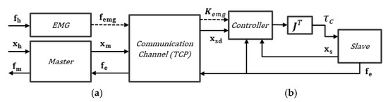
Figure 1.
Block diagram of the system using the proposed compliance-control method.
The controller is implemented based on the conventional PD controller. We propose a hybrid type controller for a control system that has high stiffness according to the user’s intention even when the contact is generated according to the user’s EMG value while the compliance control of the robot manipulator is applied. The proposed PD controller is derived as follows:
where is the force calculated by the PD-controller; is the force calculated by the spring-model parameter for the making of the EMG-signal contribution; and are the positions of the slave and master devices, respectively; and are the velocities of the slave and the master devices, respectively; and are the constant and diagonal matrices of the PD controller, each value of the primary components corresponds to each joint; is the normalized stiffness according to EMG-signal matrix that is defined as ; and is the normalized signal defined in Section 3 with the range of 0 to 1. The is spring constant based on EMG-signal induced compliance. As in Equation (3), the is obtained by summing and . Finally, the torque is obtained using Equation (4) on the assumption the system is static or quasi-static for the simplification. The matrix is the force information matrix from the environment measured by the F/T sensor attached to the slave robot and is the reaction force of the environment limited by the maximum value , which is represented by Equation (5), as follows:
where the is the predefined maximum reaction force from the environment, and , , and are the reaction forces measured at the end effector of the slave device. Matrix C acts as a weighting factor of the compliance effect index by the muscle signal and the control signal. Therefore, the proposed controller part as shown in Figure 1 can be described as shown in Figure 2 in detail.
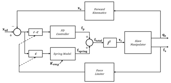
Figure 2.
Block diagram of the proposed controller.
The proposed controller can make the slave robot trace the trajectory of the master device in free space, where contact between the slave robot and the environment is nonexistent. In addition, when the human operator grasps the master device with weak grasping force while operating it with some contact force, it is possible to control the compliance according to the measured data from the force/torque sensor. When the human operator holds the master device strongly and operates it, for example, to do the assembly operation to overcome the frictional force, the stiffness of the slave robot is changed according to the contact force of the precise gripping posture measured by the EMG sensor in the same direction even when the contact occurred.
3. Identification of EMG Signal Sensing Location
3.1. EMG Signal Processing
Figure 3 depicts how the EMG signal is processed by a filtering method to extract the useful information in this work. The signal-processing procedures comprise data collection, wave rectification, mean filtering, root-mean-square (RMS) operation, and normalization, as shown in Figure 3.

Figure 3.
Signal process diagram.
First, the EMG signal is measured by the Bagnoli-4 EMG System of DELSYS Co. The measured EMG signal is obtained by the data acquisition system (DAQ USB-6009) of National Instrument Co. Based on the Nyquist theory, the sampling frequency was set to 1 kHz because the frequency of the human muscle is mainly between 20 Hz and 450 Hz [19,20,21].
In general, there are two types of rectification methods in EMG signal processing; the one is a half-wave rectification to exclude negative signal, and the other is a full-wave rectification that converts both the positive and negative halves of the signal to positive. Since the half-wave rectification process causes the loss of some signals, the full-wave rectification is applied to process the entire EMG signal without loss. Then, the signal has to be smoothened to eliminate the high-frequency noise signal. Numerous methods can be utilized to eliminate the high-frequency signal and to obtain the tendency of the signal [22]. In this work, the average filter of size 10 is used to eliminate the high-frequency noise signal, as it is widely chosen and easy to implement. The following signal processing step is the RMS operation step, in order to indicate a trend or characteristic at the measured voltage level , where k indicates the sampling iteration [14]. The RMS value is obtained using Equation (6), as follows:
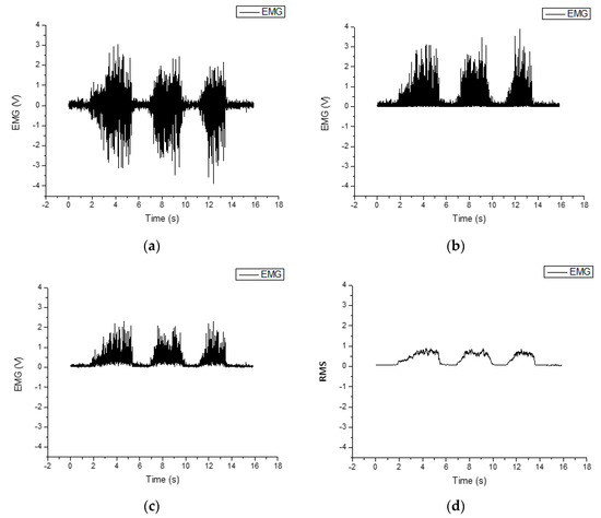
Figure 4.
The EMG signal (a), raw data after (b) rectification, (c) average filter, (d) RMS value.
This filtered EMG signal after the RMS operation is used to estimate the force magnitude exerted on the master device. The EMG signal, however, depends on measurement conditions such as the temperature, humidity, and operator skin; therefore, the filtered signal should be normalized before each operation as described in [23] as in Equation (2).
where the and denote the maximum and the minimum filtered signal value, which are measured before the operation, respectively. The value of this normalized EMG signal ranges between 0 and 100, and therefore it can be functional as the sensor through the signal processing procedure.
3.2. Location for the EMG Attachment
The surface-EMG sensor is utilized to measure how strong the human operator grasps the master device during the telemanipulation task. The accurate attachment of the surface-EMG sensor to the target muscle is critical in this work. The experiment was performed to find the appropriate muscles that cause sensitive EMG signal variation when the operator holds the master device. The candidate muscles are selected according to their unique nature [15,24]. The candidates are the abductor pollicis brevis (APB), first dorsal interosseous (FDI), flexor pollicis longus (FPL), and extensor digitorum (ED), which are related to the grasp and spread of the hand motions. The candidates are displayed in Figure 5 [15].
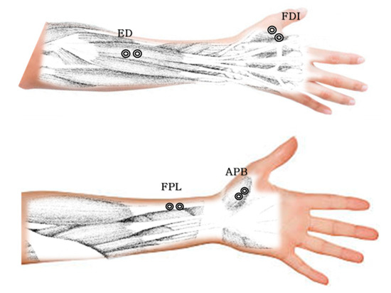
Figure 5.
Candidate for EMG signal sensing.
To determine the candidates with the maximum grasp-motion relationship, a surface-EMG sensor was attached at each candidate point, and the EMG signal was measured when a human operator held the force/torque sensor between his/her thumb and detection finger. This motion is similar to the master device holding motion. Then, it became possible to obtain the correlation between the measured force and the EMG signal at each point; therefore, the muscle that is related to the holding motion could be identified by the correlation. Figure 6 shows the holding motion and the surface-EMG location.
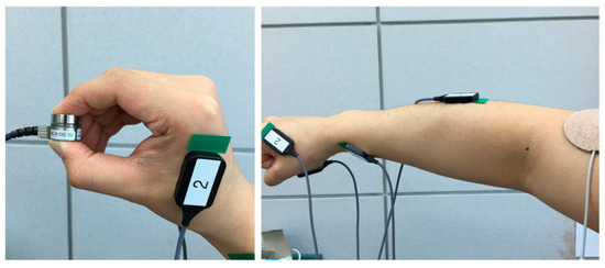
Figure 6.
Attached EMG sensors and gripping of F/T sensor.
The experiment was conducted with three types of force model. When the operator holds the force/torque sensor using the visual feedback from the monitor screen, it is possible to measure the force/torque profiles on three different types of force model, as shown in Figure 7, Figure 8 and Figure 9. The force modes are composed of 5 N and 30 N periodical steps, and 10 N, 20 N, and 30 N stair profiles.
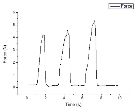
Figure 7.
Experimental results on 5N press.
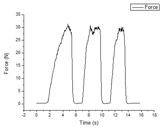
Figure 8.
Experimental results on 30N press.
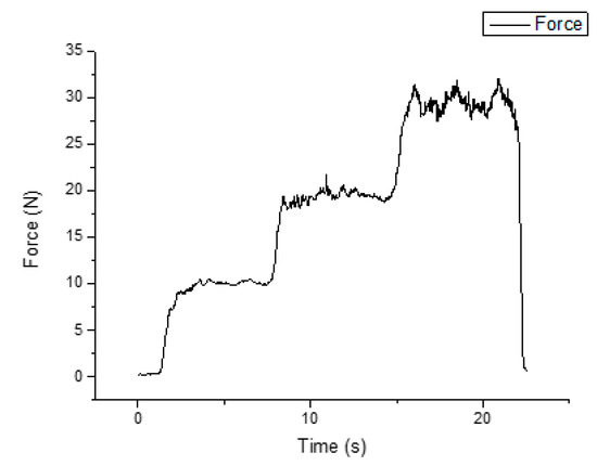
Figure 9.
Experimental results on 10, 20, and 30 N stair step press.
The Pearson-correlation method [21] was employed to find the muscle that highly correlates with the precision-grip motion. Figure 10 and Figure 11 show the filtered EMG signals according to the force models. As shown in Figure 10, the RMS value range of the APB is the biggest among the candidate muscles.
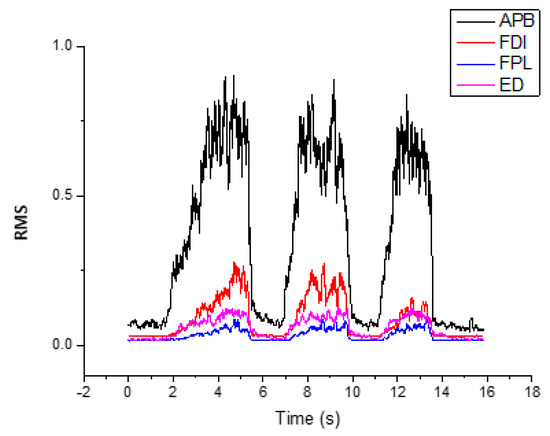
Figure 10.
RMS value of filtered EMG signals according to the muscles.
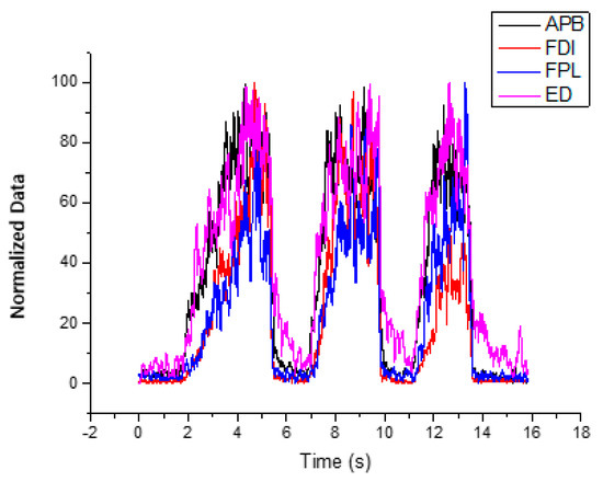
Figure 11.
Filtered EMG signals according to the muscles.
Table 1 shows the Pearson correlation in the force mode. The APB and FDI values are similar here, but the slave robot needs to be sensitive to transmit small stiffness changes such as a 5 N periodical step force. Moreover, the selected-muscle interference should be the smallest except for the precision-grip motion. Figure 12 shows the filtered EMG signal that is affected by the wrist motion during the precision-gripping posture. Because the APB muscle is the most sensitive for gripping posture and less affected by the wrist motion, we selected the APB muscle.

Table 1.
Pearson correlation value for each muscle in the force mode.
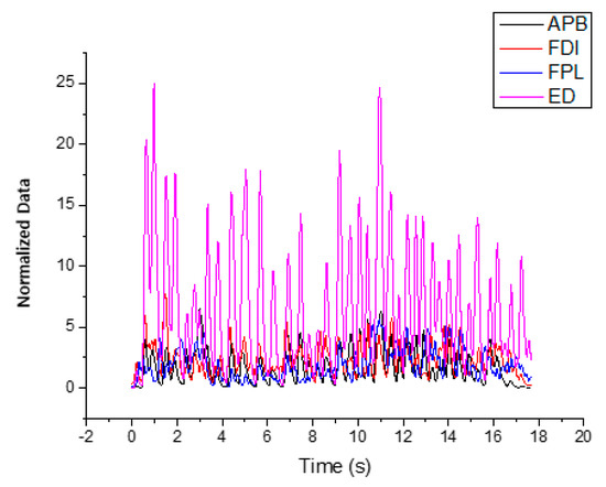
Figure 12.
Filtered EMG signal related to the motions except precision grip.
4. Implementation of Telemanipulation System
4.1. System Structure
This session describes the bilateral-control method in terms of telemanipulation, and the entire system schematic with the two-channel architecture is presented in Figure 13. A human operates the master device, and the slave robot follows the trajectory of the master device. When the slave robot is in contact with the environment, the reaction force is measured by the force/torque sensors at its end effector. The measured reaction force is transmitted to the master device so that the human can feel the reaction force through the master device. The information between the master device and the slave robot is exchanged through transmission control protocol (TCP) communication with the LAN. The control system is implemented in the subnet, thereby neglecting the communication-time delay.
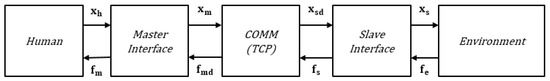
Figure 13.
The Entire system schematic with the two-channel architecture.
The PHANToM Omni and PHANToM Premium 1.5 A of Sensable are used as the master device and the slave robot, respectively. The master device can measure its three-axis position and the three-axis orientation but can provide only three-axis reaction force at its end effector to the user. The PHANToM Premium 1.5 A was utilized as the slave robot since three actuators at three joints can be used to control the motion. The ATI-manufactured SI-125-03 force/torque sensor is attached to the end effector of the slave robot and is made use of to measure the contact force between the slave robot and the environment. Figure 14 shows the devices that were utilized in the experiment.
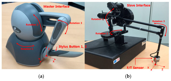
Figure 14.
The master device and the slave robot for the experimental setup. (a) master interface; (b) slave robot.
The control method introduced in this paper is also used in the re-targeting method for versatility. Although the structure between the master device and slave robot is the same, the re-targeting method is necessary in consideration of the independent structure of the general master slave [14].
4.2. Control Architecture
The slave robot that is shown in Figure 15 is modelled as the three-axis 3R type conventional manipulator. This system is controlled by the torque-control method. Each actuator can operate 3.5 N-mm at its maximum moment force. The system kinematics and Jacobian are required for the use of the re-targeting function and the Cartesian transformation. First, the forward kinematics is obtained by Equation (8), as follows:
where and are derived from Figure 16, and expressed as in Equations (9) and (10), respectively.
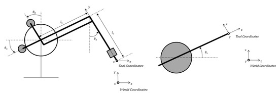
Figure 15.
Modeling parameters of the slave robot.
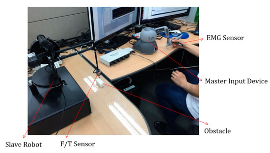
Figure 16.
Developed experimental setup.
From this transformation, the position and orientation of the end effector can be presented in the Cartesian space. Moreover, the slave-actuator torque can be transformed using Equation (11). Furthermore, the Jacobian can be obtained from , as follows:
5. Experimental Evaluation
Figure 16 shows the experimental block diagram and the posture, respectively. As previously indicated, the PHANToM Omni was utilized as the master device, the PHANToM Premium 1.5 A was used as the slave interface, the ATI SI-125-03 is the force/torque sensor, and the Bagnoli-4 Surface-EMG was attached onto the human arm. Therefore, the human subject remotely operates the slave robot by manipulating the master device while attaching the EMG sensor in his/her hand.
In order to check the variable stiffness function and the position error in the proposed control method, the experiment to contact with a hard obstacle is carried out, as shown in Figure 16. First, the master device was manipulated in free space to check the performance of the controller.
Figure 17 and Figure 18 show 3-DOF moving trajectories and the errors of the position control. Figure 18 shows the results of the position control at each joint in a time domain. The steady-state error of the PD controller is shown, and the maximum errors are measured 7.9 mm in X-axis, 7.77 mm in Y-axis, and 5.71 mm in Z-axis. The average errors are 3.00 mm in X-axis, 2.67 mm in Y-axis, and 2.22 mm in Z-axis.
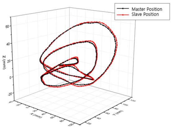
Figure 17.
Free space motion of the master-slave experimental system.
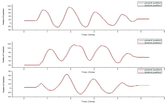
Figure 18.
Position tracking result according to perpendicular translational axis.
The experiments of the three different scenarios were conducted as follows: The first scenario was a constant stiffness, the second scenario was a variable stiffness according to the force/torque sensor, and the last scenario was a variable stiffness according to both the force/torque sensor and the EMG signal. Figure 19 shows the results of the first scenario, which means that the matrix C is zero. As shown in Figure 19, it can be seen that when a stiffness of the slave robot is fixed, a large reaction force can be generated even when a small contact is made with an object. Figure 20 shows the second scenario results. In the case of having variable stiffness as described above, the size of the force is reduced, so that more stable contact is possible.
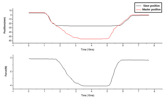
Figure 19.
Constant stiffness.
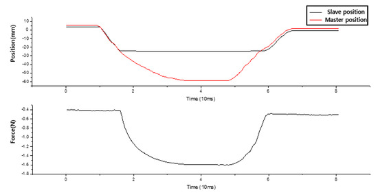
Figure 20.
Variable stiffness according to the force/torque sensor.
Figure 21 shows the results for the last- scenario results. The EMG signal at time T1 indicates the moment when the user increases the muscle force. At this time, since user required high stiffness of the slave robot, the slave robot instantaneously responded with increased stiffness. In addition, the slave robot becomes more compliant when it finishes the task requiring high stiffness at T2 and reduces the muscle force, and does not have to pay much attention to avoid the contact with the surrounding objects. Table 2 shows the data from the quantitative inspection that was conducted among the experiments.
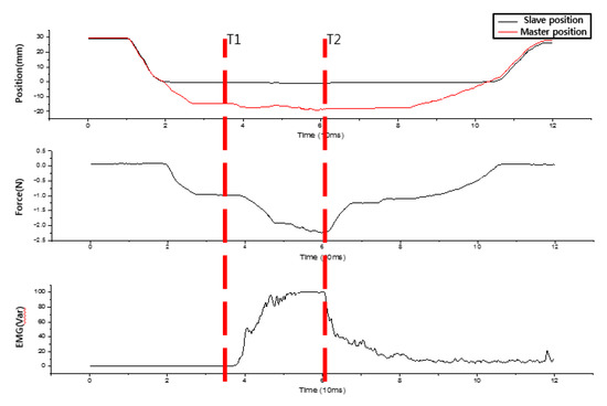
Figure 21.
Variable stiffness according to both the force/torque sensor and the EMG signal.
Table 2.
Performance index for experimental type.
The value of the last-experiment result is similar to the other results in terms of the force versus the position error (Table 2). The estimated stiffness values of the first and second experiments, 0.07~0.12 (N/mm), are in the range of the estimated stiffness values of the last experiment. In the last experiment, the estimated stiffness is larger than the expected stiffness because of the F/T sensor noise and modelling error of the controller. The reason underpinning the higher force versus the position error is related to the stable control of the force limitation; therefore, the performance of the position control in free space is soundly compared with the constant-stiffness experiment. In addition, the variable stiffness can be detected according to the EMG and force/torque sensors.
To prove the performance of the proposed control method, an experiment was conducted with soft paper tissue. As shown in Figure 22, the tissue near the slave robot’s end-effector was divided into two types of zones. The black zones are not to be damaged and the red zones are to be damaged. The user was instructed to perform a selectively punctured operation according to the color of the paper tissue which is easily damaged during the teleoperation. The performance of the proposed control method was proven as sound, as shown in Figure 23. In this empirical test, subjects easily completed their mission to punctuate the tissue with the variation of the stiffness according to EMG signal by changing their gripping force. In the experiment, in case of fixed stiffness, the force of the environment felt through the master input device allows the user to adjust the position at the red side, minimizing the damage and performing the task. However, in the case of the conventional compliance control method, it was difficult to perform the task indicated on the black-colored surface. On the other hand, the variable stiffness control method using EMG, which is proposed in this paper, showed the better performance as shown in the Figure 23.
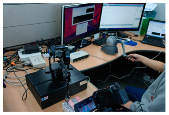
Figure 22.
Experimental setup of the experiment.
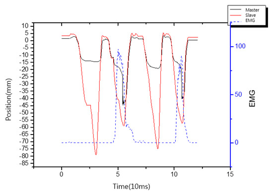
Figure 23.
Position of master-slave according to the EMG signal.
6. Conclusions
In this paper, a compliance-control method for a slave manipulator with the EMG signal during telemanipulation is proposed. The EMG signal was used to change the stiffness of the slave robot. In order to find the most relevant muscle for EMG signal during precision grip, the differences between the EMG signals from the four muscles were analyzed using the Pearson correlation. The APB indicated the strongest relationship regarding the precision-grip motion. Therefore, a PD controller utilizing an EMG signal is proposed. Regarding this controller, the force/torque sensor and the EMG signal are used to determine the stiffness of the slave robot. The proposed controller is able to exert a high stiffness in free space and can vary the stiffness when contact occurs during manipulation task. In addition, even in friction situations such as those wherein grinding and assembling occur, the slave robot can be manipulated by human intervention using the EMG signal. Therefore, in relation to the proposed controller, the variable stiffness characteristic enables a more intuitive operation of the remote control because the remote operator receives feedback from the environment through the reaction force while changing the stiffness of the slave robot.
Author Contributions
Supervision and Funding Acquisition, G.-H.Y.; Writing-Review & Editing, G.-H.Y.; Conceptualization, B.A. and S.Y.K.; Writing-Original Draft Preparation, B.A.; Implementation B.A. and S.Y.K.; Software, G.-H.Y.; Data acquisition and analysis, B.A. and S.Y.K. All authors have read and agreed to the published version of the manuscript.
Funding
This work was supported in part by the Technology Innovation Program (Industrial Strategic Technology Development Program, 10060070, Development of Core Teleoperation Technologies for Maintaining and Repairing Tasks in Nuclear Power Plants) funded by the Ministry of Trade, Industry and Energy (MOTIE), Korea, in part by Korea Institute of Industrial Technology as under “The development of Intelligent Marine Robot to Improve Underwater Work Convenience” (KITECH UR180053).
Conflicts of Interest
The authors declare no conflict of interest.
References
- Yun, S.S.; Kim, M.; Choi, M.T. Easy interface and control of tele-education robots. Int. J. Soc. Robot. 2013, 5, 335–343. [Google Scholar] [CrossRef]
- Guo, J.; Guo, S.; Wei, X.; Gao, Q. A Novel tele-operation controller for wireless microrobots in-pipe with hybrid motion. Robot. Auton. Syst. 2016, 76, 68–79. [Google Scholar] [CrossRef]
- Kruse, D.; Wen, J.T.; Radke, R.J. A sensor-based dual-arm tele-robotic system. IEEE Trans. Autom. Sci. Eng. 2014, 12, 4–18. [Google Scholar] [CrossRef]
- Cui, J.; Tosunoglu, S.; Roberts, R.; Moore, C.; Repperger, D.W. A review of teleoperation system control. In Proceedings of the Florida Conference on Recent Advances in Robotics, Boca Raton, FL, USA, 8–9 May 2003. [Google Scholar]
- Hokayem, P.F.; Spong, M.W. Bilateral teleoperation:An historical survey. Automatica 2006, 42, 2015–2057. [Google Scholar] [CrossRef]
- Vukobratovic, M.; Tuneski, A. Contact Control Concepts in Manipulation Robotics—An Over View. IEEE Trans. Industrial. Electron. 1994, 41, 12–24. [Google Scholar] [CrossRef]
- Hogan, N. Impedance Control: An Approach to Manipulation: Part I, II and III. Dynam. Sys. Meas. Control 1985, 107, 8–16. [Google Scholar] [CrossRef]
- Zhang, T.; Jiang, L.; Fan, S.W.; Wu, X.Y.; Feng, W. Development and experimental evaluation of multi-fingered robot hand with adaptive impedance control for unknown environment grasping. Robotica 2016, 34, 1168–1185. [Google Scholar] [CrossRef]
- Manson, M. Compliance and Force Control for Computer Controlled Manipulators. IEEE Trans. Sys. Man Cybern. 1981, 11, 418–432. [Google Scholar] [CrossRef]
- Oh, S.R.; Kim, H.C.; Suh, I.H.; You, B.J.; Lee, C.W. A Compliance Control Strategy for Robot Manipulators using A Self-controlled Stiffness Function. In Proceedings of the 1995 IEEE/RSJ International Conference on Intelligent Robots and Systems, Human Robot Interaction and Cooperative Robots, Pittsburgh, PA, USA, 5–9 August 1995; pp. 179–184. [Google Scholar]
- Roveda, L.; Haghshenas, S.; Caimmi, M.; Pedrocchi, N.; Molinati Tosatti, L. Assisting Operators in Heavy Industrial Tasks: On the Design of an Optimized Cooperative Impedance Fuzzy-Controller With Embedded Safety Rules. Front. Robot. AI 2019, 6, 75. [Google Scholar] [CrossRef]
- Roveda, L. A User-Intention Based Adaptive Manual Guidance with Force-Tracking Capabilities Applied to Walk-Through Programming for Industrial Robots. In Proceedings of the 2018 15th International Conference on Ubiquitous Robots (UR), Honolulu, HI, USA, 26–30 June 2018; pp. 369–376. [Google Scholar]
- Aguirre-Ollinger, G.; Colgate, J.E.; Peshkin, M.A.; Goswami, A. Active-Impedance Control of a Lower Limb Assistive Exoskeleton. In Proceedings of the 2007 IEEE 10th International Conference on Rehabilitation Robotics, Noordwijk, The Netherlands, 13–15 June 2007; pp. 188–195. [Google Scholar]
- Vogel, J.; Castellini, C.; van der Smagt, P. EMG-Based Teleoperation and Manipulation with the DLR LWR-III. In Proceedings of the 2011 IEEE/RSJ Int. Conference on Intelligent Robots and Systems, San Francisco, CA, USA, 25–30 September 2011; pp. 672–678. [Google Scholar]
- Hochberg, L.R.; Bacher, D.; Jarosiewicz, B.; Masse, N.Y.; Simeral, J.D.; Vogel, J.; Haddadin, S.; Liu, J.; Cash, S.S.; van der Smagt, P.; et al. Reach and grasp by people with tetraplegia using a neurally controlled robotic arm. Nature 2012, 485, 372–375. [Google Scholar] [CrossRef] [PubMed]
- Lenzi, T.; De Rossi SM, M.; Vitiello, N.; Carrozza, M.C. Intention-based EMG control for powered exoskeletons. IEEE Trans. Biomed. Eng. 2012, 59, 2180–2190. [Google Scholar] [CrossRef] [PubMed]
- Bitzer, S.; Van Der Smagt, P. Learning EMG control of a robotic hand: Towards active prostheses. In Proceedings of the 2006 ICRA 2006 IEEE International Conference on Robotics and Automation, Orlando, FL, USA, 15–19 May 2006; pp. 2819–2823. [Google Scholar]
- Ajoudani, A.; Tsagarakis, N.; Bicchi, A. Tele-impedance: Teleoperation with impedance regulation using a body–machine interface. Int. J. Robot. Res. 2012, 31, 1642–1656. [Google Scholar] [CrossRef]
- Pezarat-Correia, Pedro, L.C.; Mil-Homens, P. A Electromiografia no Estudo do Movimento; Faculdade De Motricidade Humana: Lisboa, Portugal, 2004. [Google Scholar]
- Altimari, L.R.; Dantas, J.L.; Bigliassi, M.; Kanthack TF, D.; Moraes, A.C.; Abrão, T. Influence of Different Strategies of Treatment Muscle Contraction and Relaxation Phases of EMG Signal Processing and Analysis During Cyclic Exercise. In Computational Intelligence in Electromyography Analysis—A Perspective on Current Applications and Future Challenges; 2012; pp. 97–116. Available online: https://www.intechopen.com/books/computational-intelligence-in-electromyography-analysis-a-perspective-on-current-applications-and-future-challenges/influence-of-different-strategies-of-treatment-muscle-contraction-and-relaxation-phases-on-emg-signa (accessed on 20 February 2020). [CrossRef]
- Keman, G.; Gabriell, D.A. Essentials of Electromyography; Human Konetics: Chanmpaign, IL, USA, 2010. [Google Scholar]
- Delagi, E.F.; Peretto, A. Anatomic Guide for the Electromyographer (the Limbs); Charles C Thomas Publisher: Springfield, IL, USA, 1980. [Google Scholar]
- Hermens, H.J.; Freriks, B.; Disselhorst-Klug, C.; Rau, G. Development of recommendations for SEMG sensors and sensor placement procedures. J. Electromyogr. Kinesiol. 2000, 10, 361–374. [Google Scholar] [CrossRef]
- Kendall, F.P.; McCreary, E.K.; Provance, P.G.; Rodgers, M.; Romani, W.A. Muscles, Testing and Function: With Posture and Pain; Williams & Wilkins: Baltimore, MD, USA, 1993. [Google Scholar]


© 2020 by the authors. Licensee MDPI, Basel, Switzerland. This article is an open access article distributed under the terms and conditions of the Creative Commons Attribution (CC BY) license (http://creativecommons.org/licenses/by/4.0/).