1. Introduction
The spherical diamond wheels can be used for the grinding of complex surfaces, such as aspheric surfaces, off-axis surfaces, free-form surfaces, and also play a significant role in the optical manufacturing industry [
1,
2]. However, ultra-precision grinding is only possible provided that a periodic form truing of the diamond wheels is conducted over the whole grinding cycle [
3,
4]. The resin-bonded spherical diamond wheels are especially beneficial for obtaining better ground surface quality but are more susceptible to wear [
5]. A high-efficiency on-machine precision form truing process and a form-truing error in-situ measurement method are therefore necessary to reduce the influence of grinding wheel wear on the resulting accuracy of the grinding surface profile, thus allowing for efficient and precision grinding of complex surfaces of hard and brittle materials [
6].
On-machine precision form truing is primarily aimed to eliminate the errors caused by installation, manufacturing, wear, and other factors of the grinding wheel [
7]. The error elimination could improve the rotation and profile accuracy of the grinding wheels, which is crucial for obtaining good surface accuracy and quality [
8,
9]. The common form-truing methods that can be used for resin-bonded diamond wheels include diamond pen truing, pulsed laser truing, abrasive block truing, diamond roller truing, etc. [
10]. The single point diamond pen can achieve the purpose of truing by extruding it on the grinding wheel surface and shedding the bond materials [
11]. This method is simple, but the diamond pen wears out quickly when truing large diamond wheels. In addition, the single point diamond pen is not suitable for truing grinding wheels with complex profile [
12]. The pulsed laser truing method can sharpen and profile the grinding wheel in radial and tangential directions, respectively [
13,
14]. Although it can be used for truing resin-bonded grinding wheels, the resulting form accuracy is usually not impressive. The main difference between abrasive block truing and diamond roller truing lies in the truing tools. For abrasive block truing, in order to make the grinding wheel bond materials wear and fall off to achieve the truing purpose, sintered corundum and green silicon carbide truing tools on the diamond wheel are often used [
15]. Due to the rapid wear of the abrasive block truing tools, it is difficult to control the form-truing accuracy of the grinding wheels. However, abrasive block truing has the advantages of low cost, small truing force, and good sharpening effect [
16]. The diamond roller can achieve from truing of the grinding wheels by both grinding and rolling effects under high rotation speed [
17]. The coarse-grained electroplated diamond wheels are generally used for diamond roller truing, which results in a large truing force and has high requirement on the rigidity of the truing spindle, tool spindle, and machine tool. As the diamond roller is resistant to wear, it is easy to control the grinding wheel shape, and the resulting truing efficiency is high [
18].
Although the truing and dressing techniques of resin-bonded diamond wheels have been widely reported, relatively few reports focusing on the precision form truing of spherical diamond wheels. Chen et al. [
19] applied the generating method to precision form truing of a micro-spherical diamond wheel, where the cup truer and the grinding wheel rotate around their respective axes and make axial feed to generate the spherical surface of the grinding wheel. By this method, the profile
PV (peak to valley) value of the grinding wheel with a diameter of 1 mm is approximately 1–2 μm. Based on the generating method, the cup truer can be replaced with an electrode tool for truing the metal bonded spherical diamond wheels. Wang et al. [
20] applied the electrical discharge truing method to profile a metal-bonded spherical diamond wheel with a diameter of 3.8 mm. The profile graph showed that the achieved form-truing error can be less than 2 μm under the optimal process parameters. More research on precision form truing of spherical diamond wheel is of great significance to further improve the grinding surface form accuracy and reduce the machining allowance in the subsequent polishing process.
The in-situ measurements of the dimension and form accuracies of the grinding wheels are the critical process of on-machine form truing. The common measurement methods of grinding wheel profile include contact measurement, image acquisition method, graphite copy method, and so on [
21,
22]. The detection probe in contact measurement is highly liable to be damaged since sharp diamond abrasive particles are randomly distributed on the grinding wheel surface, which could substantially affect the detection result [
23]. The image acquisition and graphite copy methods are not suitable for profile measurement of grinding wheels with large-size and complex surface. Chromatic confocal displacement sensor and laser displacement sensor are commonly used in non-contact measurement systems. Chromatic confocal displacement sensor is based on wavelength displacement modulation technique, and possesses a sub-micron meter accuracy over a millimeter order range [
24]. Chromatic confocal profilometer has been widely used in science investigation and industry fields for its high precision and great measurement range [
25]. Zou et al. [
26] integrated a chromatic confocal measurement probe with an ultra-precision turning machine, and on-machine measurement with nanometer-level accuracy was achieved. Laser scan micrometer is based on the triangulation measurement principle, which is characterized by good stability, large measurement range, and high efficiency [
27]. It has become widely available in measurements of dimension, surface profile, and even 3D shape [
28,
29,
30]. However, the measurement accuracy is affected by the geometrical and optical conditions [
31]. For non-contact measurement of grinding wheel profile accuracy, the sensor needs to meet the requirements of precision, range, and working distance at the same time.
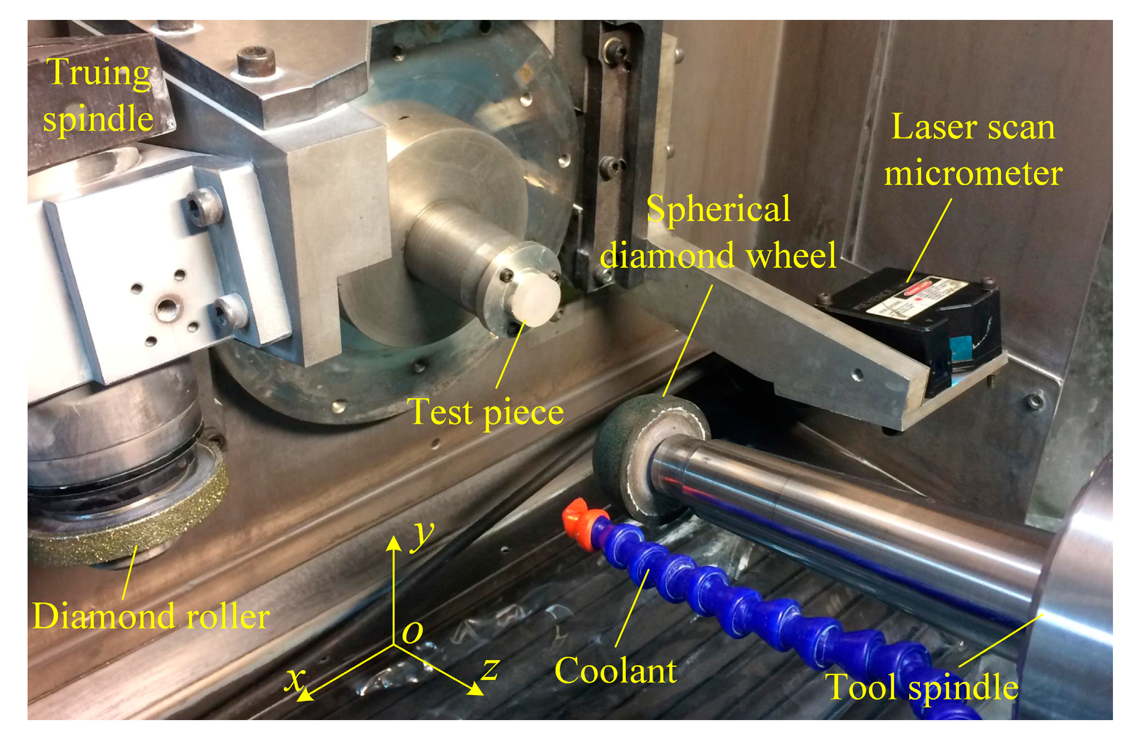
In this paper, the coarse-grained diamond roller is applied to perform precision form truing of the resin-bonded spherical diamond wheel. The non-contact in-situ measurement method of the form-truing error and the alignment error are proposed and verified by using a laser scan micrometer.
3. Measurement and Compensation of the Alignment Error
The position of the spherical diamond wheel and the laser scan micrometer in the measuring process is shown in
Figure 5a. The laser beam by the laser scan micrometer is adjusted to parallel to the
yoz-plane of the machine tool coordinate system, and coplanar with the axis of the diamond wheel. Then, the laser scan micrometer is controlled by the CNC system to scan the diamond wheel surface bottom-up linearly. The scanning direction is perpendicular to the axis of the diamond wheel. The sampling points of the laser scan micrometer are the height information of the diamond wheel surface, and the continuous sampling data constitute the profile of the spherical diamond wheel. As shown in
Figure 5b, the arc AC in the measurement results corresponds to the AC section profile of the spherical diamond wheel. After truing the spherical diamond wheel, the AC section is tested, and the least square fitting is performed. The fitting radius and residual value are the measuring radius and profile error of the spherical diamond wheel, respectively.
Based on the measurement results shown in
Figure 5b, a biarc curve-fitting method is proposed to calculate the alignment error between the truing spindle and tool spindle. As displayed in
Figure 6, the arc A’B’C’ represents the ideal spherical diamond wheel profile, and the arc ABC is the actual diamond roller trued profile. The DE arc is intercepted and fitted from the AB segment of the detected profile, and the coordinates (
xl,
yl) of the circle center
Ol as well as the arc radius
rl, are then calculated. Similarly, the GF arc is intercepted and fitted from the BC segment of the detected profile, and the position coordinates (
xr,
yr) of the circle center
Or as well as the arc radius
rr are then obtained. The distance
OlOr between the center of the two circles is the alignment error in the
x direction. When
xr >
xl, the roller is not trued to the center of the spherical diamond wheel, as shown in
Figure 6a. When
xr <
xl, the roller has passed by the center of the spherical diamond wheel, as shown in
Figure 6b.
Figure 7 shows a set of center coordinates and radius fitting values obtained by the biarc curve-fitting method. It is seen that the alignment error between the roller and the spherical diamond wheel is approximately 0.28 mm, and the diamond roller is not trued to the center of the spherical diamond wheel. The alignment error can be eliminated by introducing a “truing-detection-compensation” process. Then, the precision form truing of the resin-bonded spherical diamond wheel can be achieved. The diameter of diamond roller can be approximately considered as fixed in the actual truing process of the resin-bonded diamond wheel.
Figure 8 displays scanning electron microscope (SEM) micrographs showing the surface topography of the resin-bonded spherical diamond wheel after the diamond roller truing. The flat and regular surface of the spherical diamond wheel proves the good truing effect of the diamond roller. Part of the diamond grains were broken during the truing process, and the micro-breakage of the abrasive grains generates new sharp cutting edges. The diamond roller truing method can achieve the purposes of both shaping and sharpening. It is conducive to enhancing the grinding ability of the spherical diamond wheel, and improving both the ground surface form accuracy and the surface quality.
4. Results and Discussion
Figure 9a shows the measured line-profile of the spherical diamond wheel after diamond roller truing. The spherical diamond wheel is stationary during the measuring process. The measuring radius and the two-dimensional (2D, along the generatrix direction) form-truing error of the spherical diamond wheel can be obtained by least square fitting. As affected by the abrasive grain size and the surface micro-roughness, the measuring radius possesses a certain deviation from the actual radius, which needs to be compensated according to the ground surface form error of the test specimen. The 2D form-truing error of the spherical diamond wheel is the deviation between the measured surface profile and the fitted curve. As shown in
Figure 9b, the obtained 2D form-truing error is approximately 40 μm, which is slightly less than the average grain size of the spherical diamond wheel.
In order to validate the accuracy of the in-situ measurement results, the 2D form-truing error of the spherical diamond wheel are also measured by stylus profilometer (Form Talysurf PGI 1240, Taylor Hobson Ltd., Leicester, UK), as shown in
Figure 10. By comparing the error curves in
Figure 9b and
Figure 10, it is observed that the two measurement results have a high degree of consistency, especially the high-frequency form error of the spherical diamond wheel. The high-frequency error signals in the measurement results mainly originate from the protruding diamond grains and bond pits on the surface of the spherical diamond wheel. These grains and pits are extremely random and can be expressed by the signal amplitude in the measurement results. In addition, the amplitude detected by the stylus profilometer is less than that of the laser scan micrometer. Due to the limitation of the profiler probe size and shape, it cannot detect the bottom of the pits in the contact measurement process, this may generate an error in the peak to valley value. The 2D form-truing errors obtained by both the laser scan micrometer and the stylus profilometer cannot accurately characterize the form accuracy of the grinding wheel, as only the protruding diamond grains on the whole grinding wheel surface is functional for the ground surface form accuracy.
The highest point of the protruding diamond grains on the rotation circumference of the spherical diamond wheel is the actual effective profile in the grinding process. Therefore, the surface profile can better reflect the form accuracy of the spherical diamond wheel rather than the line-profile. One of the advantages of non-contact measurement is that the spherical diamond wheel can rotate in the detection process to obtain the surface profile.
Figure 11 shows the surface profile information of the form-trued spherical diamond wheel detected by the laser scan micrometer under a rotation speed of 600 rpm. It can be seen from
Figure 11a that the measured profile of the spherical diamond wheel is in good consistency with the fitted curve. However, the rotation of the spherical diamond wheel causes continuous change and rapid fluctuation of the measured surface, the high-frequency signals are introduced into the measured results. These high frequency signals contain not only the form error in the rotation direction but also noise signals. According to the original form error signals shown in
Figure 11b, the maximum amplitude exceeds 150 μm. In order to obtain the effective information about the enveloping profile of the protruding diamond grains, the noise signals are removed by low-pass filtering. Along with cut-off frequency increasing, more information of form-truing error in the rotation direction as well as more noise signals will be retained. However, the cut-off frequency needs to be greater than the rotational frequency of the spherical diamond wheel to avoid the radial run-out error signals being filtered out. The rotational frequency
fr of the diamond wheel is expressed as:
where,
nt is the rotation speed of the spherical diamond wheel (rpm), and
vf is the scanning movement speed in the measurement process (mm/min). According to Equation (1), under the experimental conditions of a grinding wheel rotation speed of 600 rpm and a scanning feed rate of 30 mm/min, the rotational frequency is 20 Hz. As shown in
Figure 11c, the 3D (along the generatrix and the rotation direction) form-truing error of the spherical diamond wheel is approximately 5 μm by setting the cut-off frequency of the low-pass filter to 32 Hz. The form-truing error is distributed symmetrically on both sides of the grinding wheel center.
The form accuracy of the spherical diamond wheel can be verified by grinding a test specimen, and the actual radius of the spherical diamond wheel can also be calculated based on dimension error of the ground surface. In this paper, the hot-pressed ZnS with a diameter of 20 mm is selected as the test specimen, which incurs little wear to the spherical diamond wheel. The grinding wheel rotation speed is 12,276 rpm, the feeding speed is 5 mm/min, and the grinding depth is 2 μm. The grinding surface of the test specimen is a sphere with a target radius of 25 mm in the NC program. As shown in
Figure 12a, the ground surface form error is approximately 1.6 μm without any compensation, which is determined mainly by the form-truing accuracy of the spherical diamond wheel. It can be found from
Figure 12b that the surface form error of the test specimen is mainly resulted from low-frequency fluctuations with a space period of about 2 mm, which is equivalent to the low-frequency fluctuation period of the spherical diamond wheel surface profile shown in
Figure 11c. The test specimen grinding results verified the accuracy of the 3D form-truing error that was obtained by laser scan micrometer non-contact measurement. By comparing the obtained 3D form-truing error and ground surface form error values, it is confirmable that the uncertainty of the measured form-truing error is about 3 μm for aspherical diamond wheel with a diameter of about 50 mm. In addition, the sphere radius of the test specimen is 24.9896 mm, which is 10.4 μm less than the target radius. Therefore, the measuring radius of the spherical diamond wheel is 10.4 μm smaller than the actual value. The uncertainty of the measuring radius is high related to the size and surface state of the grinding wheel, but the measuring error can be compensated by test specimen grinding. In conclusion, the accurate form-truing error as well as the actual size of the spherical diamond wheel can be obtained by combining the laser scan micrometer non-contact measurement and test specimen grinding.
5. Conclusions
In this paper, the coarse-grained diamond roller is applied to perform on-machine precision form truing of the resin-bonded spherical diamond wheel. The non-contact in-situ measurement based on a laser scan micrometer is proposed to achieve the measurement of form and alignment errors. The main conclusions include:
(1) The diamond roller truing is an efficient and feasible method for conditioning the resin-bonded spherical diamond wheel. The grinding wheel surface after truing is flat and regular, and micro-breakage of the abrasive grains generated new sharp cutting edges. The form truing of a resin-bonded spherical diamond wheel with a radius of about 24 mm and particle size of D46 was conducted after alignment error compensation, and the obtained form-truing error is approximately 5 μm.
(2) The alignment error between the diamond roller and the spherical diamond wheel can be accurately calculated by applying the proposed biarc curve-fitting method. The spherical diamond wheel with good form accuracy can be obtained by introducing a “truing-detection-compensation” process to eliminate the alignment error.
(3) The laser scan micrometer is used for non-contact in-situ measurement of the form-truing error of the spherical diamond wheel. The accuracy of the measurement results is validated by comparing with the results of the stylus profilometer. Besides, the actual form-trued diamond wheel has been employed in grinding a ZnS spherical surface, and the form accuracy is approximately 1.6 μm without any compensation. The ground surface profile shared similar characteristics with the roller-trued diamond wheel profile, confirming that the diamond roller truing and in-situ measurements methods are accurate and feasible.


