Article

Opal-Like Photonic Structuring of Perovskite Solar Cells Using a Genetic Algorithm Approach

1
Centre Spatial de Liège, STAR Institute, University of Liege, Avenue du Pré-Aily, B-4031 Angleur, Belgium
2
Laboratoire de Physique du Solide, University of Namur, Rue de Bruxelles 61, B-5000 Namur, Belgium
3
University of Liège, CESAM-GREENMAT, Allée du Six-Aout 13, B-4000 Sart Tilman, Belgium
*
Author to whom correspondence should be addressed.
Appl. Sci. 2020, 10(5), 1783; https://doi.org/10.3390/app10051783
Submission received: 30 January 2020 / Revised: 18 February 2020 / Accepted: 1 March 2020 / Published: 5 March 2020
(This article belongs to the Special Issue State of the Art of Nanosciences in Belgium)

Abstract

:

Featured Application

Applications are perovskite solar cells.

Abstract

Light management is an important area of photovoltaic research, but little is known about it in perovskite solar cells. The present work numerically studies the positive effect of structuring the photo-active layer of perovskite material. This structuration consists of a hybrid absorbing layer made of an uniform part and an opal-like part. A genetic algorithm approach allows us to determine the optimal combination among more than 1.4 × 10 9 potential combinations. The optimal combination provides an internal quantum efficiency of 98.1%, nearly 2% higher than for an equivalent unstructured photo-active layer. The robustness of the optimum against potential experimental deviations, as well as the angular dependency of the proposed structure, are examined in the present study.

1. Introduction

Crystalline Si solar cells are the most abundant technology on the photovoltaic (PV) market due to their high power conversion efficiency (PCE). The best research cell efficiency for crystalline Si to date is attributed to Amonix Inc., with a PCE of 27.6% [1]. However, due to the market being highly competitive, different routes are being investigated to cut production costs. One of them is thin film technology, which drastically reduces the amount of absorbing material. A major drawback of this approach is the high photon penetration depth around the optical bandgap of the semiconducting material, which is located at 1.08 µm for Si [2]. In 2014, Solexel manufactured a thin film crystalline Si solar cell with a PCE of 21.2% [1], with this value being 6.4% lower than Amonix’s device.
Light management inside thin film PV technologies is consequently necessary in order to enhance the amount of light entering and eventually being absorbed within the cell. Surface texturing [3,4,5,6], anti-reflective coatings [7], and use of plasmonics [8,9] or photonic crystals [10] are some of the methods explored in the recent years in order to improve the efficiency of PV devices and increase the amount of light captured inside the photo-active layer. Our attention is focused on photonic crystals, since they enable the excitation of quasi-guided resonances, allowing an enhanced electromagnetic (EM) field concentration inside the dedicated absorbing layer [11,12,13,14,15]. These kinds of phenomena intrinsically have a very narrow bandwidth. Adjusting the geometrical properties of the photonic crystal enables the position of the resonance wavelength to be tailored within the desired range, and can therefore help in solving the high photon penetration depth issue occurring around the bandgap wavelength. A peculiar characteristic of quasi-guided modes is their ability to couple with external light [16]. These modes drastically affect the transmission and reflection of light within the slab, resulting in complex resonant line shapes, which are described well by the Fano interference process [17]. This concept refers to an interaction process between resonant and broadband scattering processes.
Another strategy to enhance the PCE is to use a more absorbent PV material than Si, with a higher optical absorption coefficient, and consequently a shorter photon penetration depth. Among the emerging PV technologies, one can cite dye-sensitized solar cells (record PCE of 12.3% [1]), organic cells (record PCE of 17.4% [1]), and quantum dots cells (record PCE of 16.6% [1]), among others. The fastest growing emerging technology involves organic–inorganic perovskite solar cells (PSCs); starting from 2.2% PCE [18] in 2006, they reached 25.2% in 2019 [1]. Their high optical absorption coefficient, high diffusion length, and low fabrication costs are indubitable advantages drawing the attention of the PV community to these unique materials [19,20,21,22]. From a degradation point of view, several studies point out the fact that the structure of methylammonium lead triiodide (CH3NH3PbI3), the photo-active component used in most of the PSCs studied lately, is stable against spontaneous degradation, as long as the cells remain isolated from environmental factors, such as temperature, humidity, oxygen, and intense solar irradiation. The use of filters and encapsulation strategies for the assembly of PSCs usually protects the perovskite material from these troublemakers. However, if this is not the case, the degradation of CH3NH3PbI3 into P b I 2 and C H 3 N H 3 I can be significant, especially in presence of water. Then, the perovskite stability has been shown to be enhanced by substituting iodine with bromine or chlorine. However, the associated increase of the band gap, often exceeding 2 eV, can be detrimental in terms of accessible light absorption and consecutive power conversion [23,24].
Nevertheless, methylammonium lead triiodide still exhibits a high photon penetration depth around its bandgap (around 800 nm [22]). It severely reduces the absorption in this wavelength range, and consequently the number of electron–hole pairs that are photo-generated. Therefore, the idea of applying photonic management strategies, which have been successfully demonstrated for Si solar cells, to PSCs came along recently [25,26,27,28,29,30,31,32,33]. Inverse opal perovskite films have previously been successfully prepared and Chen et al. [27] demonstrated that an optimal radius of 200 nm results in a promising PCE of 11.7% compared to an island-like perovskite film of PCE equal to 5.6%. Ha et al. achieved a PCE of 17.1% using 600 nm-thick inverse opal perovskite films (with the radius of the spheres being equal to 50 nm) [28], while Schmager et al. experimentally demonstrated that a 2D periodic array of holes inside a perovskite film was able to excite quasi-guided modes in thin film PSCs [31]. The latter photonic management strategy showed an improved PCE of 2% compared to planar structures.
Recently, our team numerically investigated the positive impact of photonic structuring inside PSCs. Without a specific optimization scheme, we evidenced a maximal relative enhancement of 6.4% in the spectrally integrated absorbed photon flux, with the photo-active layer consisting of a monolayer of entire perovskite spheres (radius of the spheres being equal to 175 nm) instead of a homogeneous perovskite layer [33]. Additional layers of spheres increase the integrated quantum efficiency (iQE). For example, three layers of entire perovskite spheres arranged in a face-centered, cubic, closed-packed structure with ABC stacking allowed for an iQE of 96.7% over the 310–800 nm wavelength range. The 3D interconnected structure of inverse opals allows the excitation of quasi-guided modes within the active layer, which increases the photon lifetime inside the desired layer.
Off the strength of those results, the main goal of this study is to further optimize the rational structure of PSCs to be closer to experimental reality by using a genetic algorithm (GA). The GA finds a global optimum or a high-quality solution within a multi-dimensional parameter space for a dedicated problem, such as light absorption [34,35,36]. This procedure enables the smart exploration of a larger range of parameters and is particularly relevant for the absorption inside the PSCs (e.g., the thicknesses of the different layers or the radius of the spheres). The GA approach is interesting, since it finds a global optimum without specifically testing each combination (their number increases exponentially with the number of parameters). The GA does not require the computation of gradients. In contrast with algorithms such as the (quasi-)Newton method or gradient descent, the GA is able to find the global optimum of a problem, while the former methods converge to the first local optimum encountered. In contrast with a standard simulated annealing algorithm, the GA enables a collective exploration of the parameter space, since a whole population actually contributes to this exploration. The GA can easily escape the local optima, since it requires only one individual to find a better place to attract the rest of the population. Compared to a GA based on a real number encoding of the parameters, a GA that relies on binary encoding, as in this work, will account for the precision required for these parameters in every operation. Instead of improving an unnecessarily large number of digits, a binary-encoded GA will keep exploring globally before converging to a solution with just the required precision [37,38]. Combined with an intrinsic suitability for parallel computing, a binary-encoded GA is especially attractive for optical engineering problems. This approach allows us to provide a stable range of experimental parameters that will lead to robust EM absorption.
Our manuscript is organized as follows. Firstly, the design of the PSCs is discussed, explaining the rationale behind the choice of materials and the range of the different parameters under investigation in the GA optimization procedure. Secondly, we briefly introduce the numerical method used to solve Maxwell equations, our GA approach, as well as the different figures of merit used for the optimization of the absorption within the PSC. Results from the GA providing the most absorbent PSCs from a purely photonic point of view are then discussed. Furthermore, we provide maps of the iQE as a function of the radius of the perovskite spheres and the thickness of the perovskite layer. This allows us to identify stable regions of experimental parameters, providing a roadmap for further experiments. Finally, the angular dependency of the optimal solution is discussed.

2. Design of the Perovskite Solar Cell

The combination of PSCs under investigation is based on representative PV devices described in the literature [39] and is shown in Figure 1.
The incident (emergence) medium is composed of a semi-infinite, non-dispersive glass (air) slab with a refractive index n i ( n s ) of 1.5 (1). The first layer of the photonic structure consists of a uniform transparent conducting electrode layer made of fluorine-doped tin oxide (FTO), with its thickness denoted as t F T O . This thickness is the first variable for the GA optimization and varies from 50 to 800 nm. A numerical resolution of 10 nm is chosen for all parameters.
A uniform hole blocking layer made of TiO2 is placed above the photo-active hybrid perovskite layer. Its thickness is fixed to 40 nm according to optimized results from the literature [33,40,41,42]. Both refractive indices of the FTO and TiO2 layers are taken from [42]. Importantly, the optical bandgap of TiO2 is 385 nm, implying that this layer slightly absorbs incident light in the following simulations, introducing some additional parasitic absorption, namely absorption occurring outside of the photo-active layer, in the short wavelength part of the spectrum (310–385 nm).
The third layer is a hybrid photo-active layer made of a uniform homogeneous layer and of spheres of methylammonium lead triiodide (MAPbI3) perovskite arranged according to a face-centered cubic (fcc) close-packed structure (filling fraction of 0.74 ) with ABC stacking. The spheres are integrated within a mesoporous TiO2 host matrix acting as an electron-collecting electrode. At the structured perovskite–TiO2 layer interface, the spheres might be non-entire. This choice adds two advantages to the structure. It first confers more photonic flexibility for the light trapping at the interface (i.e., it introduces a new parameter that can be used during the GA optimization). Secondly, this approach involving potentially non-entire spheres formalizes a less ideal case, better reproducing the experimental reality than with entire spheres, the latter being the ideal case limit described in our previous work [33]. Therefore, the two important parameters for the structured part of the photo-active layer are (i) the radius R of the spheres and (ii) the thickness t s t r u c of the structured perovskite layer. The radius of the spheres can be tuned by selecting appropriate polystyrene beads that act as structuring agents during the synthesis of the inverse opal TiO2 porous films. In the following, R can vary between 50 nm and 1100 nm. The thickness t s t r u c can be controlled by the quantity of perovskite being infiltrated inside the spherical pores left after calcination of the TiO2 precursor solution. The thickness t s t r u c will vary between 50 nm and 2200 nm. These potentially non-entire spheres represent the opal-like subunits used in the photonic structuring strategy applied here.
The presence of a uniform perovskite layer underneath the structured part of the photo-active layer confers a hybrid character to the photo-active layer (a mix of unstructured and structured layers), differing from the previous structures investigated to date in the literature, and consequently differing from our previous study [33]. This layer is often observed experimentally when the TiO2 porous matrix is overfilled by perovskite during the infiltration process. The thickness t u n i of this uniform layer will vary between 0 (no layer) and 100 nm.
To complete the design of the PSC, a hole transporting (HT) layer made of 2,2’,7,7’-Tetrakis[N,N-di(4-methoxyphenyl)amino]-9,9’-spirobifluorene or “spiro–OMeTAD” (C81H68N4O8) is placed between the hybrid photo-active layer and a gold counter-electrode. The thickness t s p i r o of the HT layer is our last parameter, varying between 50 and 800 nm. The idea behind the variation of this parameter is to allow the spiro–OMeTAD layer to act as a Fabry–Perot cavity, maximizing the reflection of non-absorbed light by the Au counter-electrode and using constructive interferences to enhance light absorption inside the hybrid photo-active layer. The thickness of the Au layer is fixed to 100 nm, which is sufficient to almost perfectly block and reflect any remaining light (transmittance T = 0 ) [43].
This particular device design is considered here so as to focus on the purely photonic optical properties of the system and their potential impact on the efficiency of absorption in PSCs (using the iQE, as defined below). Effects related to the electronic properties are, therefore, not tackled in the present work as this would require a different approach in terms of calculation methodology and material design. The thermodynamic (un)stability of the perovskite material and the consecutively assembled PSCs, known to be potentially detrimental in reality, are not discussed here, considering that the cell constituents are protected and isolated from external degradation factors such as moisture, heat, and intense solar irradiation.
The different parameters for the GA are summarized in Table 1 below, as well as their range of variation.

3. Numerical Methods and Figure of Merits

In order to assess the absorption properties of the different PSCs made of opal-like subunits, we have to solve Maxwell equations. A perfectly adapted numerical method for solving such a stratified and periodic photonic structure is the rigorous coupled wave analysis (RCWA) [44]. The total reflectance R and total transmittance T are calculated for each incident wavelength, and the global absorptance A is deduced from the conservation of energy. Numerical convergence is ensured if a sufficient number of plane waves is taken in order to reproduce the electric permittivity and EM fields developed in the truncated 2D Fourier series. Here, this convergence is verified using 7 × 7 plane waves along the x and y directions.
In order to find the set of parameters that will provide the highest photon absorption over the considered wavelength range amongst the 1.45   × 10 9 possible combinations of the five parameters described in Table 1, we used a genetic algorithm (GA) optimization approach [45,46,47]. The idea consists of working with a population of n p o p = 50 individuals that represent possible solutions to the problem. Each individual is representative of given values for the parameters we seek to determine. A binary Gray code is used for the representation of these parameters [37,47]. We refer by DNA to the chain of bits associated with the coding of the complete set of parameters and by fitness to the function we seek to maximize (the iQE, as explained in the next paragraph). We start with a random population. The n r a n d less fit individuals are replaced by random individuals; they are transferred to the next generation ( n r a n d = 0.1 × n p o p × ( 1 p ) ) , with p = | s 0.5 | / 0.5 being a progress indicator and s the genetic similarity defined as the fraction of bits in the population whose value is identical to the best individual. We apply a rank-based roulette wheel selection on the remaining part of the population to select N = n p o p n r a n d parents (a given individual can be selected several times). For the two parents selected, we define two children for the next generation either (i) by a 1 point crossover of the parents’ DNA (probability of 70%), or (ii) by a simple replication of the parents (probability of 30%). We apply binary mutations on the DNA of the children obtained by crossover (a binary mutation rate of 0.95/ n b i t s is used, where n b i t s = 33 is the number of bits in the DNA). We finally establish a quadratic approximation of the fitness in the close neighborhood of the best individual at that time. The local optimum of this approximation (if acceptable) is injected in the next generation. After evaluation of the next generation, we apply elitism to make sure that the best solution was not lost. This strategy is repeated from generation to generation until a convergence criterion is met. We refer to our previous work for more details on this algorithm [37,38].
As mentioned above, the main goal is the determination of optimal parameters in order to maximize the PSCs’ absorption. Therefore, our fitness will be the so-called integrated quantum efficiency (iQE). This quantity is the ratio of the spectrally integrated absorbed photon flux ϕ a over the PSCs to the spectrally integrated incident photon flux ϕ i n c :
i Q E = ϕ a ϕ i n c = λ m i n λ m a x λ h c A ( λ ) S ( λ ) d λ λ m i n λ m a x λ h c S ( λ ) d λ ,
where h is the Planck constant, c the speed of light, λ the incident wavelength, and S(λ) the normalized solar spectrum (AM1.5G). The integration is performed for the absorbing wavelength range of MAPbI3 perovskite (i.e., 310–800 nm) [22]. We should point out that this chosen fitness refers to the absorption properties of the PSCs only. No electrical effects are taken into account here, since our work focuses on the photonic aspects exclusively. Consequently, the iQE fitness should not be mistaken for the PCE.
After running the GA, one obtains a high-quality solution that maximizes the fitness iQE, as well as a sampling of iQE as a function of the five parameters considered. By taking linear interpolations of this sampling, one can establish 2D maps of the fitness variation with respect to the main parameters. In our problem, the most important parameters directly influencing the useful absorption are the ones related to the hybrid photo-active layer, namely the thickness of the uniform perovskite layer t u n i , the radius of the spheres R , and the thickness of the structured perovskite layer t s t r u c . Those variables control the quantity of absorbent material inside the PSC.
In addition to the global optimum, other quantities may be useful for further experimental studies. More specifically, we might be interested in knowing the robustness of the fitness around the global optimum found by the GA. Indeed, during experimental fabrication, some imperfections might drive the realized structure away from the optimum. Using the results provided by the GA, we can assess if such a deviation from ideality is negatively impacting the performance of the device. Within a two-dimensional (2D) map of the multi-dimensional parameter space, we can average the fitness over a 2D box of dimensions l 1 × l 2 . This averaging is realized using a linear interpolation over the collected data coming from the GA optimization process. We can define Δ as the difference between the optimal fitness and the averaged fitness over the 2D box (i.e., Δ = | i Q E ( o p t i m u m ) i Q E ¯ 2 D | ). A high Δ being a sign of a relatively sharp optimum is not really robust from an experimental point of view. Therefore, another 2D region might be of prime interest for experimentalists, namely a the 2D box of the same dimensions, l 1 × l 2 , presenting the highest average fitness. This region will be referred to as the “sweet spot”, since it is more robust regarding experimental imperfections that might occur during the fabrication process. We can also evaluate how much we reduce the device performance compared to the optimum established by the GA by calculating δ = | i Q E ( o p t i m u m ) i Q E ¯ ( s w e e t   s p o t ) | . In the best case, the two 2D boxes will be fairly superposed. If not, the sweet spot might be preferred if δ is not too high (i.e., if the performances are not reduced too much).

4. Results

4.1. Optimum

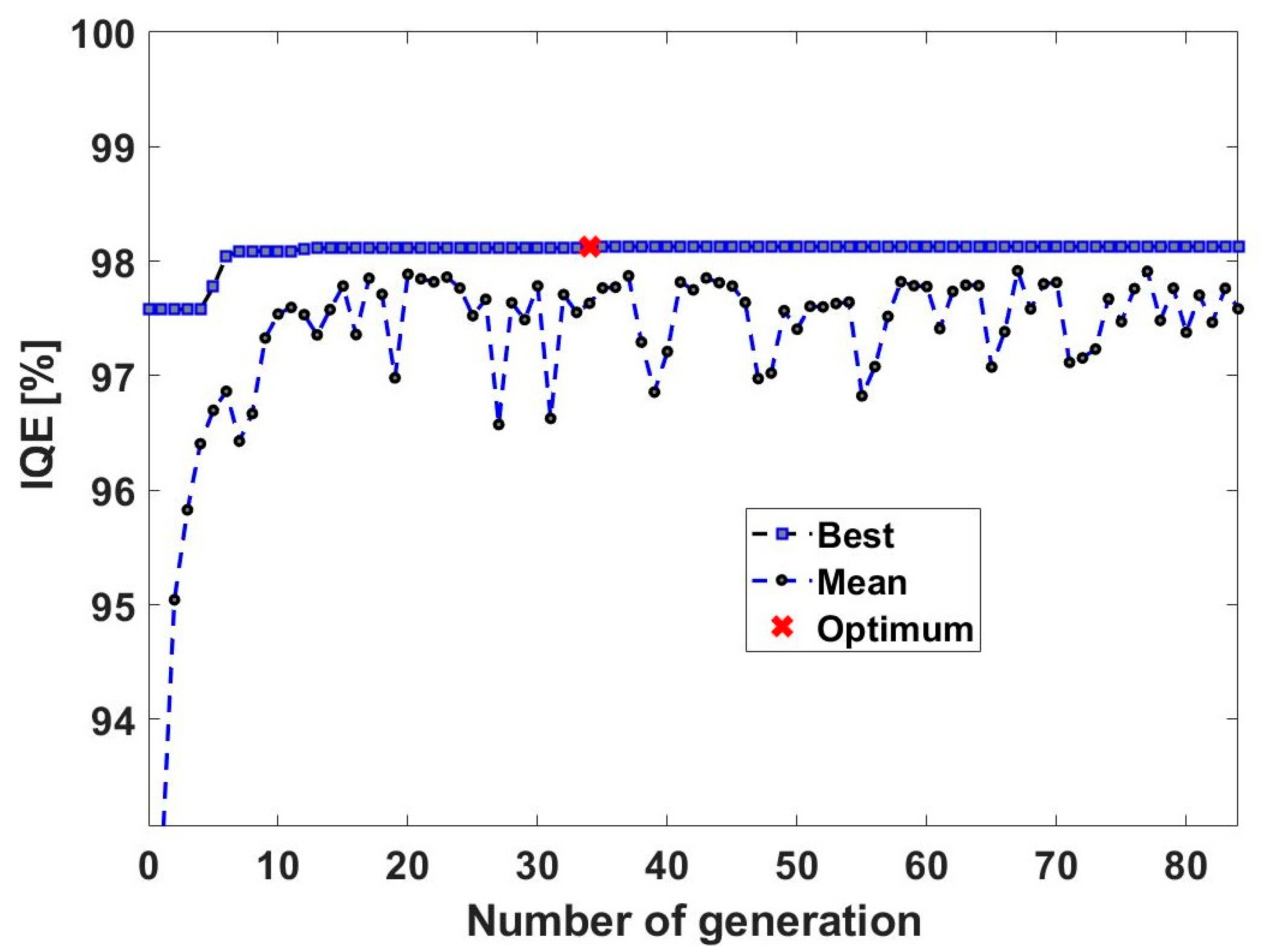
We present here the results of the GA optimization process. Figure 2 shows the best iQE and the mean iQE in the population as a function of the number of generations. A reasonably fast progression of the algorithm is noticed already after 6 generations. The global optimum is found at generation 34 (genetic similarity s of 84.8%), with a related iQE equal to 98.1%. All further generations do not provide a better iQE up to 84 generations. The global optimum found at generation 34 (red cross) corresponds then to the best combination of the parameters and is kept for all further generations. The value of 98.1% gives an idea of the averaged absorptance over the 310–800 nm wavelength range. The parameters for this global optimum are summarized in Table 2 below.
The corresponding structure encompasses four entire spheres and part of a fifth sphere on top of the structured perovskite layer. It can be noticed that the iQE is maximal for high values of t u n i (80 nm, where the maximal allowed value was 100 nm) and t s t r u c (2080 nm, where the maximal allowed value was 2200 nm). Logically, more absorption occurs inside the PSCs if more absorbing material is present.
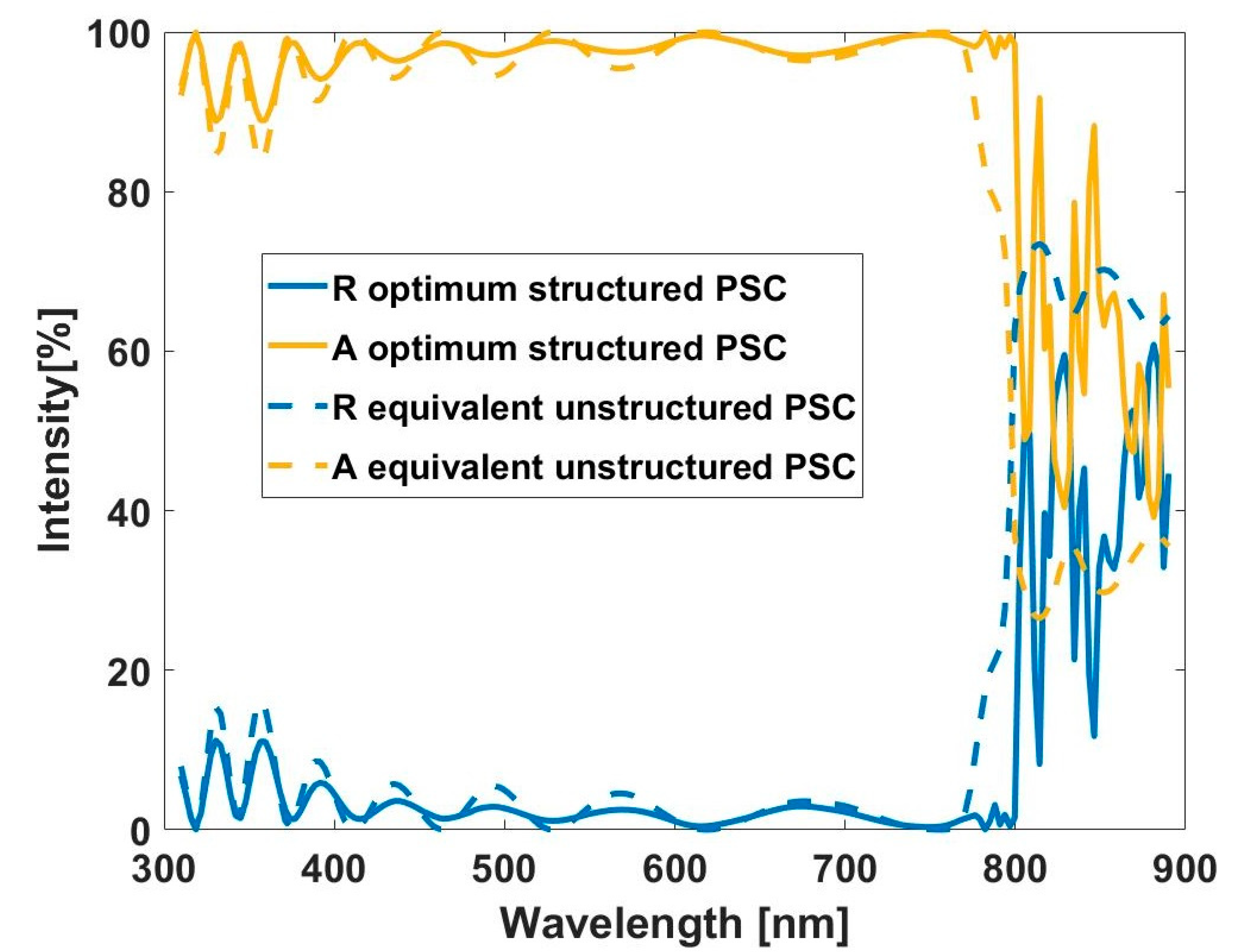
One can compare the difference between structured and unstructured PSCs by considering an equivalent layer of uniform perovskite with the parameters for the optimal iQE ( t u n i = 80   n m and t s t r u c = 2080   n m ). This equivalent thickness is given by t e q = t u n i + 0.74 × t s t r u c = 1620   n m . The corresponding iQE is 96.2%. The corresponding photonic enhancement factor, G p h o t = ( i Q E ( s t r u c t u r e d ) i Q E ( u n s t r u c t u r e d ) ) / ( i Q E ( s t r u c t u r e d ) × 100 , is equal to 2%. This confirms the positive impact on light absorption of structuring of the photo-active layer. A closer examination of the absorptance spectrum (Figure 3) reveals an enhanced absorptance just before the optical bandgap of perovskite. This was indeed the expected goal of structuring the photo-active layer. Quasi-guided modes are excited inside the perovskite spheres [33] and the GA optimization favors the spheres with the right radius, with the Fano resonance positioned close to the optical bandgap. It should be noted that the peaks present above 800 nm are related to parasitic absorption, and therefore are not directly useful for the production of electron-hole pairs without additional knowledge of the electrical properties of excitons in perovskite. Parasitic absorption (in T i O 2 for example) is always included in our calculations, and therefore the obtained results should be considered as an upper maximal value. It is interesting to note that the optimized thickness for the HT layer outputted by the GA optimization is close to the value present in the literature ( t s p i r o = 240 nm instead of 250 nm [40,41]).

4.2. Robustness of the Optimum

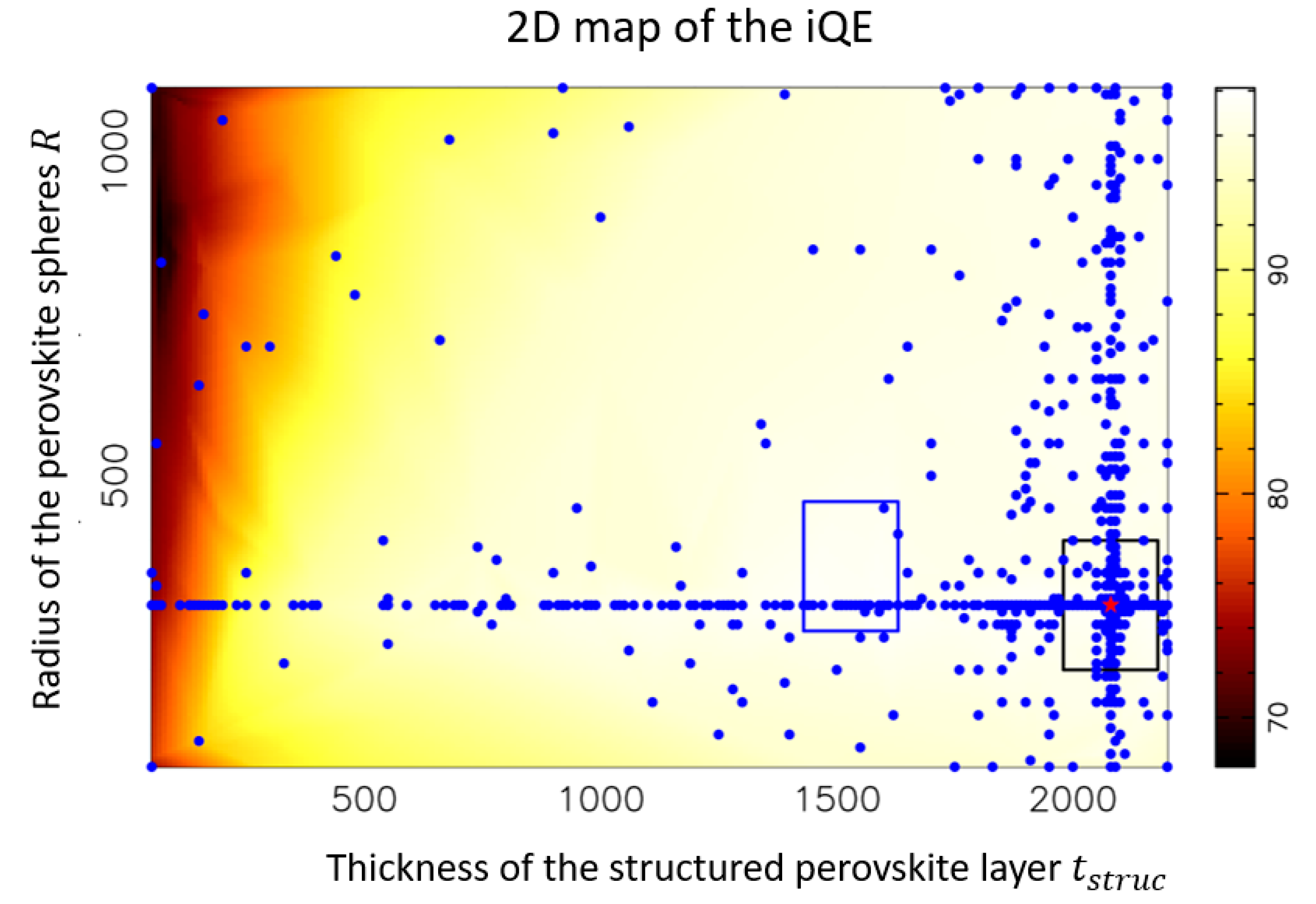
It is interesting to quantify the robustness of the optimum provided by the GA algorithm with respect to potential experimental deviations from ideality. We present in Figure 4 and Figure 5 two 2D maps showing the linear interpolations of the iQE as a function of the radius of the perovskite spheres, R ; the thickness of the structured perovskite layer, t s t r u c ; and the thickness of the perovskite uniform layer, t u n i . Those are the three main parameters responsible for useful absorption inside the PSC. The optimal values (Table 2) are labeled with a red star. The blue dots indicate the parameters where the iQE has been evaluated exactly. As we can observe, the GA has explored a lot of combinations around the optimum, indicating the reliability of the solution. The R t s t r u c 2D map (Figure 4) shows two distinct 200 nm × 200 nm 2D boxes. The black box centered around the optimum determined by the GA provides an average iQE of 97.0% (average of interpolated fitness values in this 2D plane), thus Δ = 1.1%, showing a reasonably robust optimum. The blue box refers to the sweet spot. It can be seen that the sweet spot does not overlap with the maximum established by the GA. The averaged iQE inside the sweet spot is 97.3%, providing a δ of 0.9%. Since δ < Δ , it confirms the interest of the sweet spot for the R t s t r u c parameters.
Regarding the t u n i t s t r u c 2D map (Figure 5), a reasonably good overlap between the sweet spot and the 2D box centered around the optimum can be observed. The 2D boxes measure 40 nm ( t u n i ) by 200 nm ( t s t r u c ). We find that Δ = 0.4 % and δ = 0.3 % . Even if δ < Δ , the difference is smaller and there is no reason to choose the parameters from the sweet spot over the optimum ones.
One can state from the above results that the optimum found by the GA optimization process is quite robust regarding any imperfection that might occur during the experimental fabrication process, regarding the parameters that are the most sensitive to the iQE.

4.3. Angular Dependency

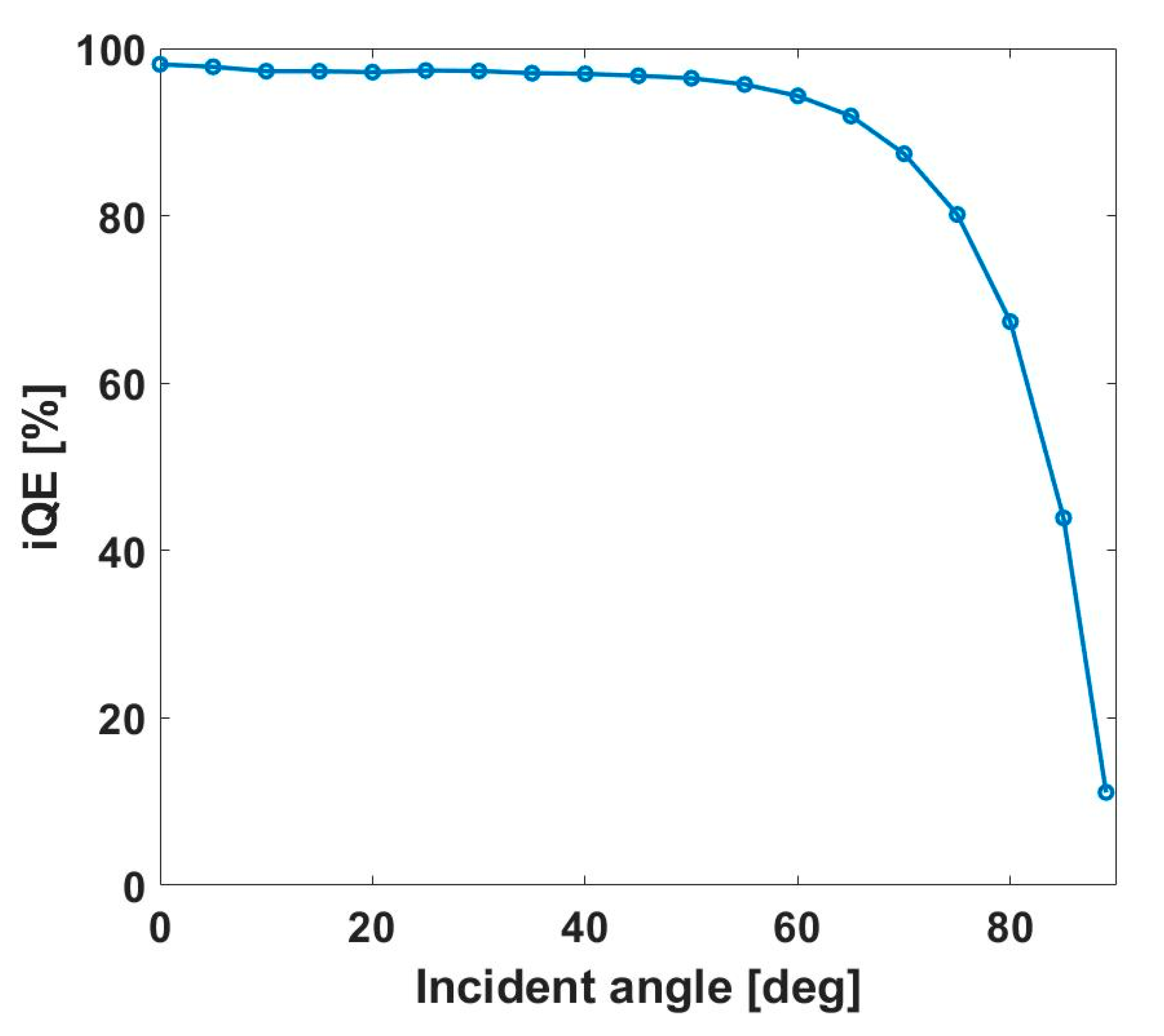
We are now interested in the angular dependency of the optimal combination found by the GA. Unpolarized incident EM radiation is sent in the PSCs. Figure 6 shows the iQE as a function of the incident angle θ , with steps of 5°. The iQE is found to be reasonably stable regarding the angle of incidence up to 75°. The main factor limiting the absorption of light is the Fresnel reflection at the FTO interface. It should be noted that no other specific light-trapping strategies were developed here, except for the photo-active layer. Anti-reflection coatings or surface structuration of the FTO layer may increase the light coupling.

5. Conclusions

The present study numerically investigates photonic structuring of the photo-active layer within PSCs. A genetic algorithm approach constrains the 1.4 × 10 9 potential parameter combinations down to an optimal configuration, giving an internal quantum efficiency of 98.1% over the considered wavelength range (310–800 nm). The presence of a hybrid uniform-structured photo-active layer shows an iQE value 2% higher than an equivalent unstructured photo-active layer. The structuring consists of perovskite spheres arranged in an fcc closed-packed structure with ABC stacking. This allows the excitation of the quasi-guided mode in order to provide higher light trapping within the photo-active layer. The proposed structure is robust against experimental deviations that may occur in the thicknesses of the perovskite layers or the radius of the perovskite spheres. It also presents stable angular dependency. Nevertheless, as the present study only focuses on photonic aspects, further work should take into consideration the electronic effects before considering any realistic implementation within a working PSC.

Author Contributions

Conceptualization, M.L., A.M. (Alexandre Maye) P.P., J.D., A.M. (Anthony Maho), C.H., and J.L.; methodology, M.L., A.M. (Alexandre Maye), P.P., J.D., A.M. (Anthony Maho), C.H., and J.L.; software, M.L. and A.M. (Alexandre Maye); formal analysis and investigation, M.L. and A.M. (Alexandre Maye); optimization, A.M. (Alexandre Maye); supervision, J.L.; project administration, J.L. and C.H.; funding acquisition, J.D., C.H., and J.L.; original draft preparation, M.L.; writing—review and editing, A.M. (Alexandre Maye), A.M. (Anthony Maho), P.P., J.D., C.H., and J.L. All authors have read and agreed to the published version of the manuscript.

Funding

This research was funded by Fédération Wallonie-Bruxelles (grant for Concerted Research Actions). Computational resources were provided by the Consortium des Équipements de Calcul Intensif (CÉCI), funded by the Fonds de la Recherche Scientifique de Belgique (F.R.S.-FNRS) under Grant No. 2.5020.11 and by the Walloon Region. Al.M. is funded by the Fund for Scientific Research (F.R.S.-FNRS) of Belgium. He is a member of NaXys, Namur Institute for Complex Systems, University of Namur, Belgium.

Acknowledgments

Rudi Cloots, director of GREENMAT, Olivier Deparis, director of LPS, and fellow team members.

Conflicts of Interest

The authors declare no conflict of interest. The funders had no role in the design of the study; in the collection, analyses, or interpretation of data; in the writing of the manuscript, or in the decision to publish the results.

References

  1. Best Research-Cell Efficiency Chart|Photovoltaic Research|NREL. Available online: https://www.nrel.gov/pv/cell-efficiency.html (accessed on 30 December 2019).
  2. Streetman, B.; Sanjay, B. Solid State Electronic Devices, 5th ed.; Prentice Hall: Upper New Jersey River, NJ, USA, 2000; p. 524. [Google Scholar]
  3. Sher, M.-J.; Winkler, M.T.; Mazur, E. Pulsed-laser hyperdoping and surface texturing for photovoltaics. MRS Bull. 2011, 36, 439–445. [Google Scholar] [CrossRef]
  4. Zhao, J.; Wang, A.; Green, M.A. 19.8% efficient “honeycomb” textured multicrystalline and 24.4% monocrystalline silicon solar cells. Appl. Phys. Lett. 1998, 73, 1991. [Google Scholar] [CrossRef]
  5. Dewan, R.; Marinkovic, M.; Noriega, R.; Phadke, S.; Salleo, A.; Knipp, D. Light trapping in thin film silicon solar cells with submicron surface texture. Opt. Express 2009, 17, 23058–23065. [Google Scholar] [CrossRef] [PubMed]
  6. Müller, J.; Rech, B.; Springer, J.; Vanecek, M. TCO and light trapping in silicon thin film solar cells. Sol. Energy 2004, 77, 917–930. [Google Scholar]
  7. Kumar Raut, H. Anti-reflective coating: A critical, in-depth review. Energy Environ. Sci. 2011, 4, 3779–3804. [Google Scholar] [CrossRef]
  8. Atwater, H.; Polman, A. Plasmonics for improved photovoltaic devices. Nat. Mater. 2010, 9, 205–213. [Google Scholar] [CrossRef] [PubMed]
  9. Ferry, V.E.; Munday, J.N.; Atwater, H.A. Design considerations for plasmonic photovoltaics. Adv. Mater. 2010, 22, 4794–4808. [Google Scholar] [CrossRef]
  10. Joannopoulos, J.D. Photonic Crystals: Molding the Flow of Light, 2nd ed.; Princeton University: Princeton, NJ, USA, 2008. [Google Scholar]
  11. Mihi, A.; Calvo, M.E.; Anta, J.A.; Mi, H. Spectral response of opal-based dye sensitized solar cells. J. Phys. Chem. C 2008, 112, 13–17. [Google Scholar] [CrossRef] [Green Version]
  12. Mihi, A.; Mi, H. Origin of light-harversting enhancement in colloidal photonic crystal base dye-sensitized solar cells. J. Phys. Chem. B 2005, 109, 15968–15976. [Google Scholar] [CrossRef] [Green Version]
  13. Tanaka, Y.; Kawamoto, Y.; Fujita, M.; Noda, S. Enhancement of broadband optical absorption in photovoltaic devices by band-edge effect of photonic crystals. Opt. Express 2013, 21, 20111–20118. [Google Scholar] [CrossRef]
  14. Guldin, S.; Hüttner, S.; Kolle, M.; Welland, M.E.; Müller-Buschbaum, P.; Friend, R.H.; Tétreault, N.; Steiner, U. Dye-sensitized solar cell based on a three-dimensional photonic crystal. Nano Lett. 2010, 10, 2303–2309. [Google Scholar] [CrossRef] [PubMed] [Green Version]
  15. Ha, L.; Colodrero, S.; Mihi, A.; Häggman, L.; Ocaña, M.; Boschloo, G.; Hagfeldt, A.; Míguez, H. Porous one-dimensional photonic crystals improve the power-conversion efficiency of dye-sensitized solar cells. Adv. Mater. 2009, 21, 764–770. [Google Scholar]
  16. Fan, S.; Joannopoulos, J.D. Analysis of guided resonances in photonic crystal slabs. Phys. Rev. B 2002, 65, 235112. [Google Scholar] [CrossRef] [Green Version]
  17. Fano, U. Effects of configuration interaction on intensities and phase shifts. Phys. Rev. 1961, 124, 1866–1878. [Google Scholar] [CrossRef]
  18. Kojima, A.; Teshima, K.; Shirai, Y.; Miyasaka, T. Novel photoelectrochemical cell with mesoscopic electrodes sensitized by lead-halide compounds. In Meeting Abstracts; MA2007-02; The Electrochemical Society: Pennington, NJ, USA, 2007. [Google Scholar]
  19. Lang, L.; Yang, J.-H.; Liu, H.-R.; Xiang, H.J.; Gong, X.G. First-principles study on the electronic and optical properties of cubic ABX3 halide perovskite. Phys. Lett. A 2014, 378, 290–293. [Google Scholar] [CrossRef] [Green Version]
  20. Green, M.A.; Jiang, Y.; Soufiani, A.M.; Ho-Baillie, A. Optical properties of photovoltaic organic-inorganic lead halide perovskite. J. Phys. Chem. Lett. 2015, 6, 4774–4785. [Google Scholar] [CrossRef]
  21. Shirayama, M.; Kadowaki, H.; Miyadera, T.; Sugita, T.; Tamakoshi, M.; Kato, M.; Fujiseki, T.; Murata, D.; Hara, S.; Murakami, T.N.; et al. Optical transitions in hybrid perovskite solar cells: Ellipsometry, density functional theory, and quantum efficiency analyses for ch3nh3pbi 3. Phys. Rev. Appl. 2016, 5, 014012. [Google Scholar] [CrossRef] [Green Version]
  22. Löper, P.; Stuckelberger, M.; Niesen, B.; Werner, J.; Filipič, M.; Moon, S.J.; Yum, J.H.; Topič, M.; De Wolf, S.; Ballif, C. Complex refractive index spectra of CH3NH3PbI3 perovskite thin films determined by spectroscopic ellipsometry and spectrophotometry. J. Phys. Chem. Lett. 2015, 6, 66–71. [Google Scholar]
  23. Tenutta, E.; Zheng, C.; Rubel, O. Thermodynamic origin of instability in hybrid halide perovskites. Sci. Rep. 2016, 6. [Google Scholar] [CrossRef] [Green Version]
  24. Ciccioli, A.; Latini, A. Thermodynamics and the intrinsic stability of lead halide perovskites ch3nh3pbx3. J. Phys. Chem. Lett. 2018, 9, 3756–3765. [Google Scholar] [CrossRef]
  25. Schünemann, S.; Chen, K.; Brittman, S.; Garnett, E.; Tüysüz, H. Preparation of organometal halide perovskite photonic crystal films for potential optoelectronic applications. ACS Appl. Mater. Interfaces 2016, 8, 25489–25495. [Google Scholar]
  26. Meng, K.; Gao, S.; Wu, L.; Wang, G.; Liu, X.; Chen, G.; Liu, Z. Two-dimensional organic-inorganic hybrid perovskite photonic films. Nano Lett. 2016, 16, 4166–4173. [Google Scholar] [CrossRef] [PubMed]
  27. Chen, B.-X.; Rao, H.-S.; Chen, H.-Y.; Li, W.-G.; Kuang, D.-B.; Su, C.-Y. Ordered macroporous CH3NH3PbI3 perovskite semitransparent film for high-performance solar cells. J. Mater. Chem. A 2016, 4, 15662–15669. [Google Scholar] [CrossRef]
  28. Ha, S.-J.; Heo, J.H.; Im, S.H.; Moon, J.H. Mesoscopic CH 3NH 3PbI 3 perovskite solar cells using TiO2 inverse opal electron-conducting scaffolds. J. Mater. Chem. A 2017, 5, 1972–1977. [Google Scholar] [CrossRef]
  29. Chen, K.; Tüz, H. Morphology-controlled synthesis of organometal halide perovskite inverse opals. Angew. Chem. 2015, 54, 13806–13810. [Google Scholar] [CrossRef] [PubMed]
  30. Dewalque, J.; Henrist, C.; Loicq, J. Light-harvesting capabilities of dielectric sphere multilayers. Phot. Phon. Prop. Eng. Nanos. 2018. [Google Scholar] [CrossRef]
  31. Schmager, R.; Hossain, I.M.; Schackmar, F.; Richards, B.S.; Gomard, G.; Paetzold, U.W. Light coupling to quasi-guided modes in nanoimprinted perovskite solar cells. Sol. Energy Mater. Sol. Cells 2019, 201, 110080. [Google Scholar] [CrossRef]
  32. Schmager, R.; Gomard, G.; Richards, B.S.; Paetzold, U.W. Nanophotonic perovskite layers for enhanced current generation and mitigation of lead in perovskite solar cells. Sol. Energy Mater. Sol. Cells 2019, 192, 65–71. [Google Scholar] [CrossRef]
  33. Lobet, M.; Pierre, P.; Jennifer, D.; Anthony, M.; Olivier, D.; Catherine, H.; Jérôme, L. Efficiency enhancement of perovskite solar cells based on opal-like photonic crystals. Opt. Express 2019, 27, 32308–32322. [Google Scholar] [CrossRef]
  34. Mayer, A.; Bay, A. Optimization by a genetic algorithm of the light-extraction efficiency of a GaN light-emitting diode. J. Opt. 2015, 17, 025002. [Google Scholar] [CrossRef] [Green Version]
  35. Mayer, A.; Gaouyat, L.; Nicolay, D.; Carletti, T.; Deparis, O. Multi-objective genetic algorithm for the optimization of a flat-plate solar thermal collector. Opt. Express 2014, 22, A1641. [Google Scholar] [CrossRef] [PubMed]
  36. Mayer, A.; Muller, J.; Herman, A.; Deparis, O. Optimized absorption of solar radiations in nano-structured thin films of crystalline silicon via a genetic algorithm. Proc. SPIE 2015, 9546, 95461N-01. [Google Scholar] [CrossRef]
  37. Mayer, A.; Lobet, M. UV to near-infrared broadband pyramidal absorbers via a genetic algorithm optimization approach. Proc. SPIE 2018, 10671, 1067127-1-11. [Google Scholar] [CrossRef]
  38. Mayer, A.; Lobet, M. A genetic algorithm for addressing computationally expensive optimization problems in optical engineering. Jordan J. Phys. 2019, 12, 17–36. [Google Scholar]
  39. Jung, H.S.; Park, N.-G. Perovskite solar cells: From materials to devices. Small 2015, 11, 10–25. [Google Scholar] [CrossRef]
  40. Saliba, M.; Correa-Baena, J.-P.; Wolff, C.M.; Stolterfoht, M.; Phung, N.; Albrecht, S.; Neher, D.; Abate, A. How to make over 20% efficient perovskite solar cells in regular n-i-p and inverted p-i-n architectures. Chem. Mater. 2018, 30, 4193–4201. [Google Scholar] [CrossRef]
  41. Hussain, I.; Tran, H.P.; Jaksik, J.; Moore, J.; Islam, N.; Uddin, M.J. Functional materials, device architecture and flexibility of perovskite solar cell. Emergent Mater. 2018, 1, 133–154. [Google Scholar] [CrossRef] [Green Version]
  42. Ball, J.M.; Stranks, S.D.; Hörantner, M.T.; Hüttner, S.; Zhang, W.; Ramirez, I.; Riede, M.; Johnston, M.B.; Friend, R.H.; Snaith, H.J.; et al. Optical properties and limiting photocurrent of thin film perovskite solar cells. Energy Environ. Sci. 2015, 8, 602–609. [Google Scholar] [CrossRef]
  43. Shahbazyan, T.V.; Stockman, M.I. Plasmonics: Theory and Applications; Springer: Berlin, Germany, 2013. [Google Scholar]
  44. Moharam, M.G.; Gaylord, T.K. Rigorous coupled-wave analysis of planar-grating diffraction. J. Opt. Soc. Am. 1981, 71, 811–818. [Google Scholar] [CrossRef]
  45. Goldberg, D.E. Genetic Algorithms in Search, Optimization and Machine Learning; Addison-Wesley: Boston, MA, USA, 1989. [Google Scholar]
  46. Haupt, R.L.; Werner, D.H. Genetic Algorithms in Electromagnetics; John Wiley & Sons: Hoboken, NJ, USA, 2007. [Google Scholar]
  47. Eiben, A.E.; Smith, J.E. Introduction to Evolutionary Computing, 2nd ed.; Springer: Berlin, Germany, 2007. [Google Scholar]
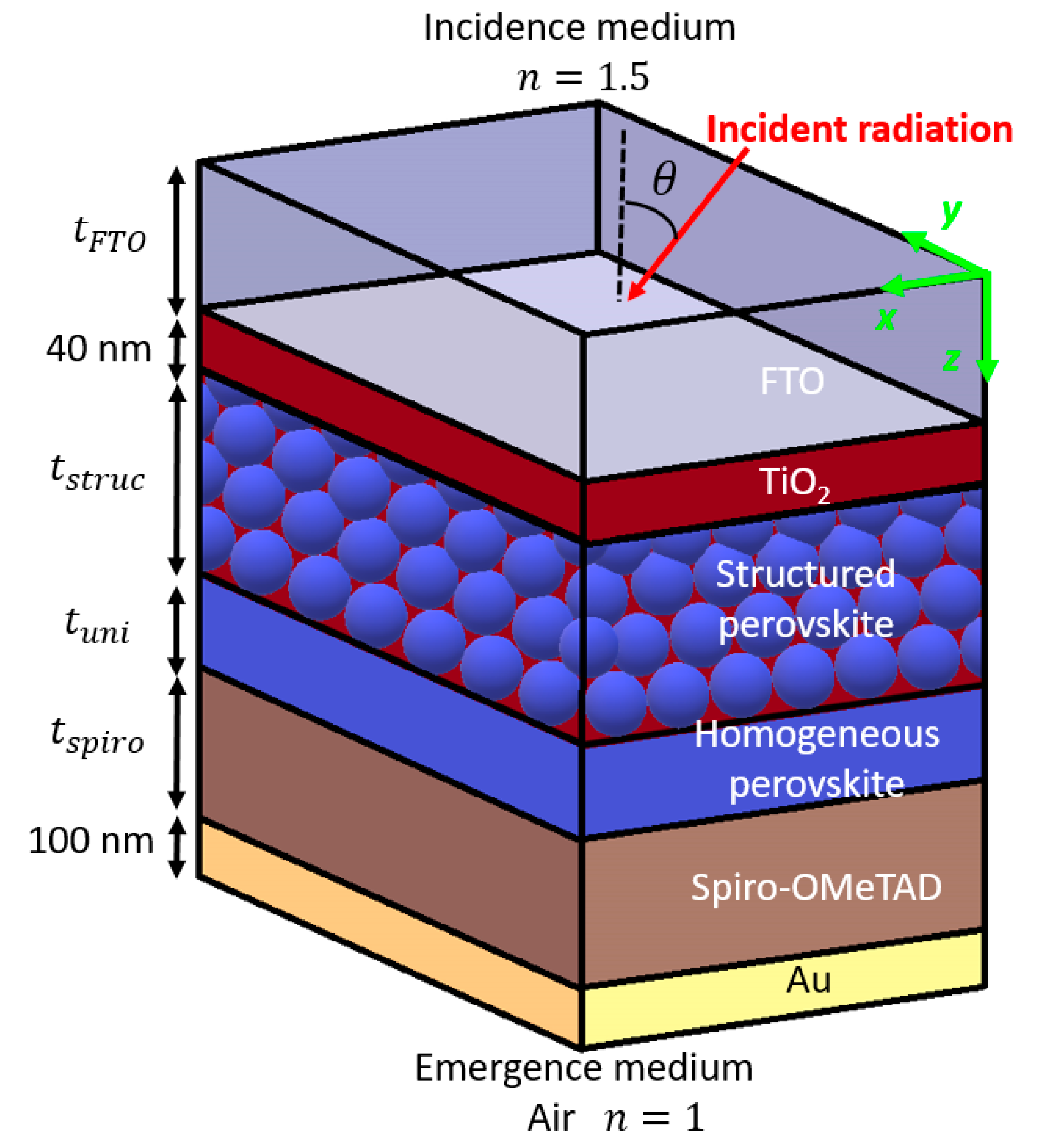
Figure 1. Schematic of a perovskite solar cell (PSC) using a hybrid photo-active layer made of structured and homogeneous methylammonium lead triiodide (MAPbI3) perovskite subunits. The structured part is made of perovskite spheres with radius R , arranged according to ABC stacking. The thicknesses of the fluorine-doped tin oxide (FTO) layer ( t F T O ) , the homogeneous perovskite layer ( t u n i ) , the opal-like structured layer ( t s t r u c ), and the 2,2’,7,7’-Tetrakis[N,N-di(4-methoxyphenyl)amino]-9,9’-spirobifluorene (spiro–OMeTAD) layer ( t s p i r o ) , as well as the radius R of the spheres, are the parameters for the genetic algorithm (GA) optimization. The thicknesses of the T i O 2 blocking layer and of the Au layer are fixed to 40 and 100 nm, respectively, while the refractive index of the incident (emergence) medium is set to 1.5 (1).
Applsci 10 01783 g001
Figure 2. Convergence of the integrated quantum efficiency (iQE) as a function of the number of generations, showing the best (square) and the mean (circle) iQE in the population in the first 84 generations when optimizing the PSCs. The combination giving the optimal iQE is found after 34 generations (red cross). Between generation 34 and 84, no better solution is found by the GA. The parameters for the optimal combination are listed in Table 2.
Applsci 10 01783 g002
Figure 3. Absorptance (yellow) and reflectance (blue) spectra for the optimal combination, providing an iQE of 98.1% (solid lines) for the PSCs. Comparison is made with an unstructured PSC containing the same volume of absorbing material (dashed lines).
Applsci 10 01783 g003
Figure 4. A 2D map of the iQE as a function of the radius of the perovskite spheres R and the thickness of the structured perovskite layer t s t r u c , two of the main parameters regarding absorption in the PSCs. Blue dots indicate evaluation of the iQE made by the GA, the red star indicates the optimal combination, the blue box indicates the sweet spot, and the black box indicates the 200 nm × 200 nm box around the optimal combination.
Applsci 10 01783 g004
Figure 5. A 2D map of the iQE as a function of the thickness of the homogeneous perovskite layer t u n i and the thickness of the structured perovskite layer t s t r u c , two of the main parameters regarding absorption in the PSCs. Blue dots indicate evaluation of the iQE made by the GA, the red star indicates the optimal combination, the blue box indicates the sweet spot, and the black box indicates a 40 nm ( t u n i ) × 200 nm ( t s t r u c ) box around the optimal combination.
Applsci 10 01783 g005
Figure 6. Integrated quantum efficiency (iQE) as a function of the incidence angle for unpolarized light for the optimal combination.
Applsci 10 01783 g006
Table 1. Parameters considered for GA optimization of the perovskite solar cells (PSCs) and their range. A numerical resolution of 10 nm is chosen for all parameters.
Parameter NameMinimum ValueMaximum Value
Thickness of the transparent conducting electrode fluorine-doped tin oxide FTO layer t F T O 50 nm800 nm
Thickness of the uniform perovskite layer t u n i 0 nm100 nm
Radius of the perovskite spheres R 50 nm1100 nm
Thickness of the structured perovskite layer t s t r u c 50 nm2200 nm
Thickness of the hole transporting spiro–OMeTAD layer t s p i r o 50 nm800 nm
Table 2. Optimum parameters provided by the GA optimization process.
Parameter NameOptimum Value
Thickness of the transparent conducting electrode fluorine-doped tin oxide FTO layer t F T O 710 nm
Thickness of the uniform perovskite layer t u n i 80 nm
Radius of the perovskite spheres R 300 nm
Thickness of the structured perovskite layer t s t r u c 2080 nm
Thickness of the hole transporting spiro–OMeTAD layer t s p i r o 240 nm