Article

Biomechanical Assessment of Vertebroplasty Combined with Cement-Augmented Screw Fixation for Lumbar Burst Fractures: A Finite Element Analysis

1
Department of Biomedical Engineering, National Yang-Ming University, 112 Taipei, Taiwan
2
Department of Orthopedics, Shuang Ho Hospital, Taipei Medical University, 235 New Taipei City, Taiwan
3
Department of Orthopedic Surgery, School of Medicine, College of Medicine, Taipei Medical University, 110 Taipei, Taiwan
4
Department of Orthopedic Surgery, Taipei Municipal Wanfang Hospital, Taipei Medical University, 116 Taipei, Taiwan
5
Graduate Institute of Biomedical Materials and Tissue Engineering, College of Biomedical Engineering, Taipei Medical University, 116 Taipei, Taiwan
*
Authors to whom correspondence should be addressed.
Appl. Sci. 2020, 10(6), 2133; https://doi.org/10.3390/app10062133
Submission received: 30 December 2019 / Revised: 19 March 2020 / Accepted: 20 March 2020 / Published: 21 March 2020
(This article belongs to the Special Issue Orthopaedic and Rehabilitation Engineering)

Abstract

:
A hybrid fixation method, using a combination of vertebroplasty and cement-augmented screws, has been demonstrated as a useful technique for securing osteoporotic burst fractures. The purpose of this study was to assess changes in the range of motion (ROM) and stress in the spine after treating a lumbar burst fracture with this hybrid method. Five finite element models were developed: (a) intact lumbar spine (INT), (b) INT with vertebroplasty at L3 (AwC), (c) two-segment fixation of AwC (AwC-TSF), (d) AwC-TSF model with cement-augmented screws (AwC-TSF-S), and (e) INT with an L3 burst fracture treated with two-segment fixation (TSF). After loading, the models were evaluated in terms of the ROM of each motion segment, stiffness of fusion segments, and stresses on the endplates and screws. The results showed that the TSF model has a larger ROM at the instrumented segments than both the AwC-TSF and AwC-TSF-S models. The stiffness at L2–L4 under extension and lateral bending in AwC-TSF, AwC-TSF-S and TSF was approximately nine times greater than the INT model. In conclusion, the hybrid fixation method (AwC-TSF-S) results in a stiffer construct and lower ROM at instrumented segments, which may also reduce the risk of fracture of adjacent vertebrae.

1. Introduction

Pedicle instrumentation is considered a safe and effective technique for treating osteoporotic burst fractures because of the stability offered to the spine in the initial postoperative period [1,2,3]. Instrumented fixation is often used to limit the movement of one or two segments in an effort to preserve spinal motion following a thoracolumbar burst fracture.
A number of studies comparing long segment fixation (stabilization of two levels above and below the fracture level) and short segment pedicle instrumentation reported a higher number of hardware-related failures with short segment fixation, such as screw bending, screw pull-out at upper segments, and screw fracture at long term follow-up [4,5,6].
Methods for treating thoracolumbar burst fractures aim to decompress the spinal canal and stabilize the spine to prevent progressive kyphotic spinal deformity. A hybrid fixation method using vertebroplasty and cement-augmented screws has been demonstrated as a practical technique for treating such burst fractures [7,8]. Kim et al. [9] reported that patients treated with cement-augmented short segment fixation, with or without posterolateral bone fusion, better maintained the vertebral height, and were less susceptible to screw loosening than patients treated with non-cement-augmented short segment fixation with posterolateral bone fusion.
Increasing the bending strength and pull-out strength of cement-augmented screws has been proposed as a method for improving long-term fixation [10], but the biomechanical effect of secondary fractures and adjacent vertebral bodies filled with bone cement on the adjacent segments is not clear. Secondary fractures at adjacent vertebral bodies after percutaneous vertebroplasty remains a serious complication, and may place the segment at greater risk of developing osteoporosis [11,12]. Cho et al. [13] reported that high stiffness-augmented bone cement increases the stress on the inferior endplate and cortical bone at the adjacent vertebral body. However, no studies to date have examined how a hybrid fixation method using vertebroplasty and cement-augmented screws may affect the adjacent vertebral bodies following treatment of an osteoporotic burst fracture.
Post-traumatic kyphotic deformity or non-union/secondary vertebral fractures can be detrimental to a patient’s lifestyle and often cause persistent back pain and spinal instability [14]. Biomechanical studies have shown that long-segment fixation is superior to four-screw constructs for unstable thoracolumbar burst fractures, because it increases the stiffness of the implant and reduces the collapse rate of the fractured body [15]. However, short-segment fixation can preserve the mobility of motion segments, and hence, is becoming a popular alternative for unstable burst fractures. But, the downside of using short-segment fixation alone, is that it has been reported with a high incidence of implant failure and secondary kyphotic deformity [4,5,6]. Theoretically, cement augmentation can provide anterior support for vertebral burst fractures, allowing for short-segment posterior fixation with cement-augmented pedicle screws which can enhance the anchoring strength and bending stiffness of the segment. This hybrid fixation method combines vertebroplasty with short-segment cement-augmented fixation. However, few studies to date have evaluated the effect of augmentation on the adjacent vertebral endplate [13]. The aim of this study was to evaluate the effect of cement augmentation on adjacent vertebrae after osteoporotic vertebroplasty supplemented with cement-augmented screws for the treatment of thoracolumbar burst fractures. In addition, biomechanical data from pedicle screws with and without bone cement augmentation in a short-segment fixation model was evaluated.

2. Materials and Methods

A finite element model of 5-level intact lumbar spine was created using the software ANSYS 15.0 (ANSYS Inc., Canonsburg, PA, USA). The geometry of the intact vertebrae was obtained from the CT images of a healthy male. In order to simplify the model, a specialized command in ANSYS was used to rotate, translate and scale the L3 vertebral body to produce the L1, L2, L4 and L5 vertebral bodies. These bodies were then aligned as a lordotic intact lumbar spine (INT), as shown in Figure 1a. Details of model validation, material properties (Table 1) and convergency testing are included in previous studies [16,17,18,19,20]. Figure 1a illustrates the complete lumbar model including vertebrae (L1–L5), intervertebral discs (IVDs) and seven ligaments. The IVDs are composed of an annulus fibrosus and nucleus pulposus, with the ground substance embedded with 12 double-crosslinked fiber layers. The annulus fibrosus was considered as an incompressible and hyper-elastic material modeled using a 2-parameter (C1, C2) Mooney–Rivlin formulation [18], while the nucleus pulposus was considered as an incompressible fluid.
Five finite element models were developed in this study: (a) intact lumbar spine (INT) without implants (Figure 1a); (b) INT model with augmentation with cement at L3 to simulate a burst fracture (30% cancellous bone were replaced by bone cement) with anatomical reduction (AwC); (c) AwC model with two-segment fixation at L2–L4 (AwC-TSF, Figure 1b); (d) AwC-TSF model with cement-augmented (cylindrical cement volume 1.0 cm3) pedicle screws (AwC-TSF-S, Figure 1c); (e) INT model with an L3 burst fracture with anatomical reduction and two-segment fixation at L2/L4 only (TSF, Figure 1b). The implant used in this study was a CB PROT II Posterior Spinal System (Chin Bone Corp., Taiwan; US FDA 510(k): K142655), which is composed of titanium alloy screws of diameter 5.5 mm connected by titanium alloy rods (Figure 1b). All implants were modeled using 8-node solid elements.
The interfaces between facet articular surfaces were treated as standard contact pairs at all levels. A hybrid multidirectional test method developed by Panjabi [21] was used to assess the effect of implantation on the levels adjacent to the fusion segment. The upper surface of the first lumbar vertebra was first loaded with a 150 N axial load, and then subjected to a pure unconstrained moment. All degrees of freedom on the bottom nodes of the fifth vertebra of all models were constrained. The moment was increased in increments of 0.36 Nm until the ROM of the model (L1–L5) achieved 17° in flexion, 10° in extension, 12° in left lateral bending and 10° in left torsion.
This study investigated lumbar motion and stress, including the ROM of each motion segment, the stiffness of fusion segments, stresses on endplates and pedicle screws, and peak disc stresses under flexion, extension, torsion and left lateral bending.

3. Results

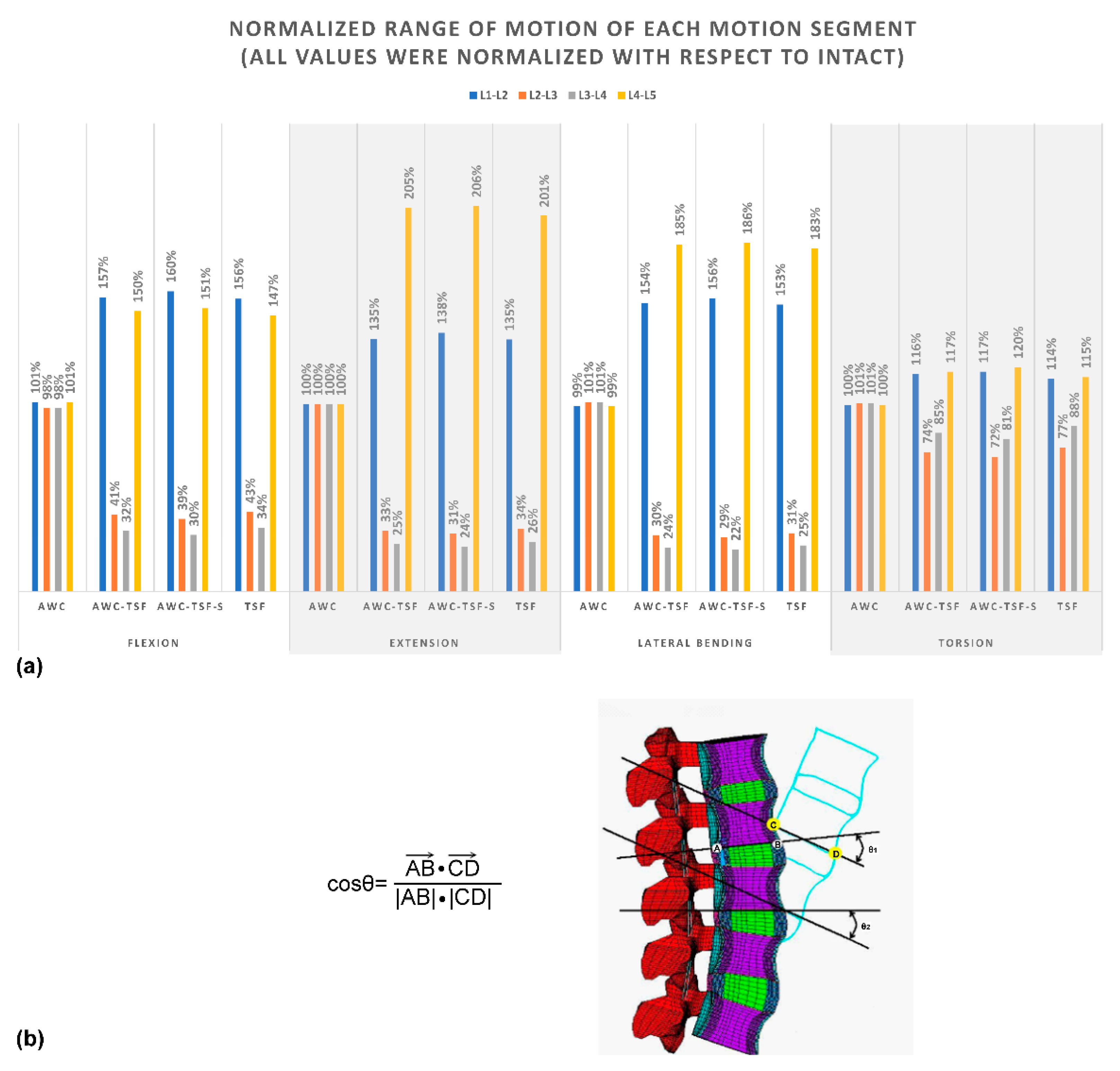
Table 2 and Table 3 and Figure 2 show that, in comparison to the INT model, the ROM decreased at the L2–L3 and L3–L4 segments in all instrumented (AwC-TSF, AwC-TSF-S and TSF) models in flexion, while the ROM of the AwC model was similar to the INT model at each motion segment. The ROM of the instrumented models was similar in flexion, extension, lateral bending and torsion, and the maximum ROM (over 200% increase over INT) occurred at L4–L5 in extension.
Figure 3 shows that the stiffness of the instrumented models (AwC-TSF, AwC-TSF-S and TSF) was similar under all motions, and increased considerably at the L2–L4 segments, with the stiffness of the instrumented models being approximately nine times greater than the INT model when under extension and lateral bending. The stiffness of the cement augmentation model was similar to the INT model in all motions.
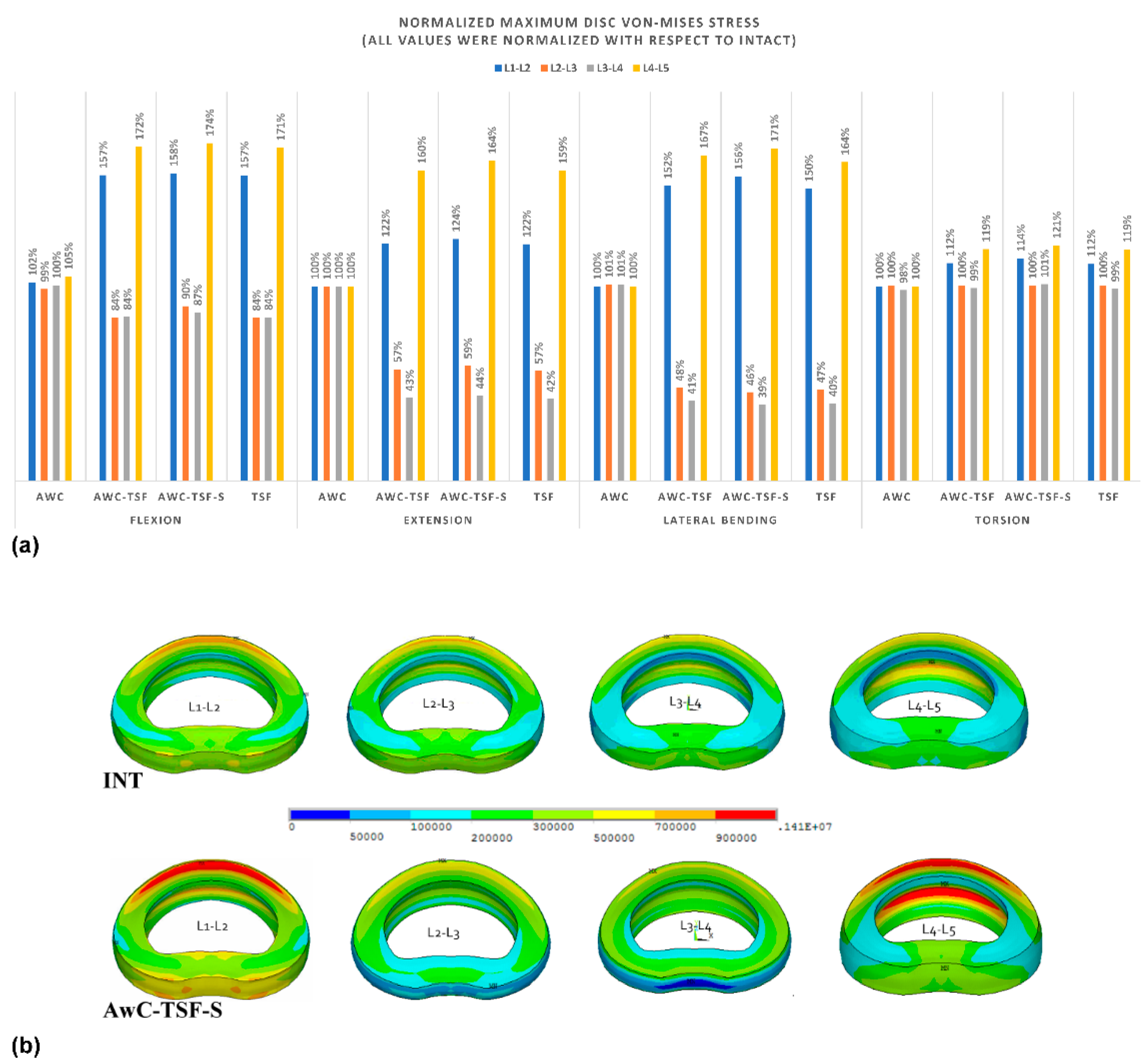
The disc stress at the instrumented segments (L2–L3 and L3–L4) decreased in comparison to the INT model in flexion (maximum decrease of 16% in AwC-TSF and TSF), extension (maximum decrease of 58% in TSF) and left lateral bending (maximum decrease of 61% in AwC-TSF-S). However, in contrast, the disc stress increased at the adjacent levels (L1–L2 and L4–L5), as shown in Figure 4. The disc stress in the AwC model was similar to the INT model at each level.
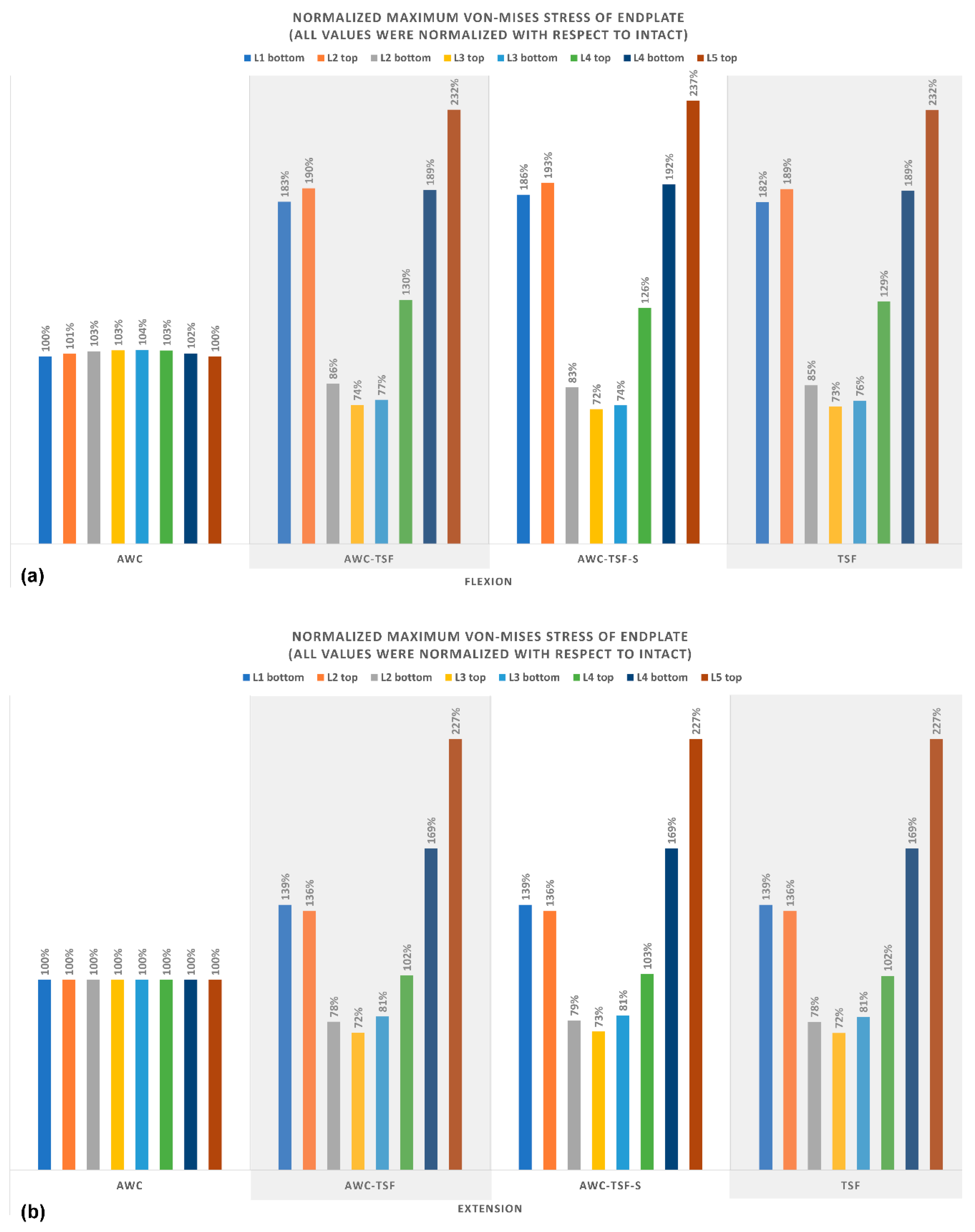
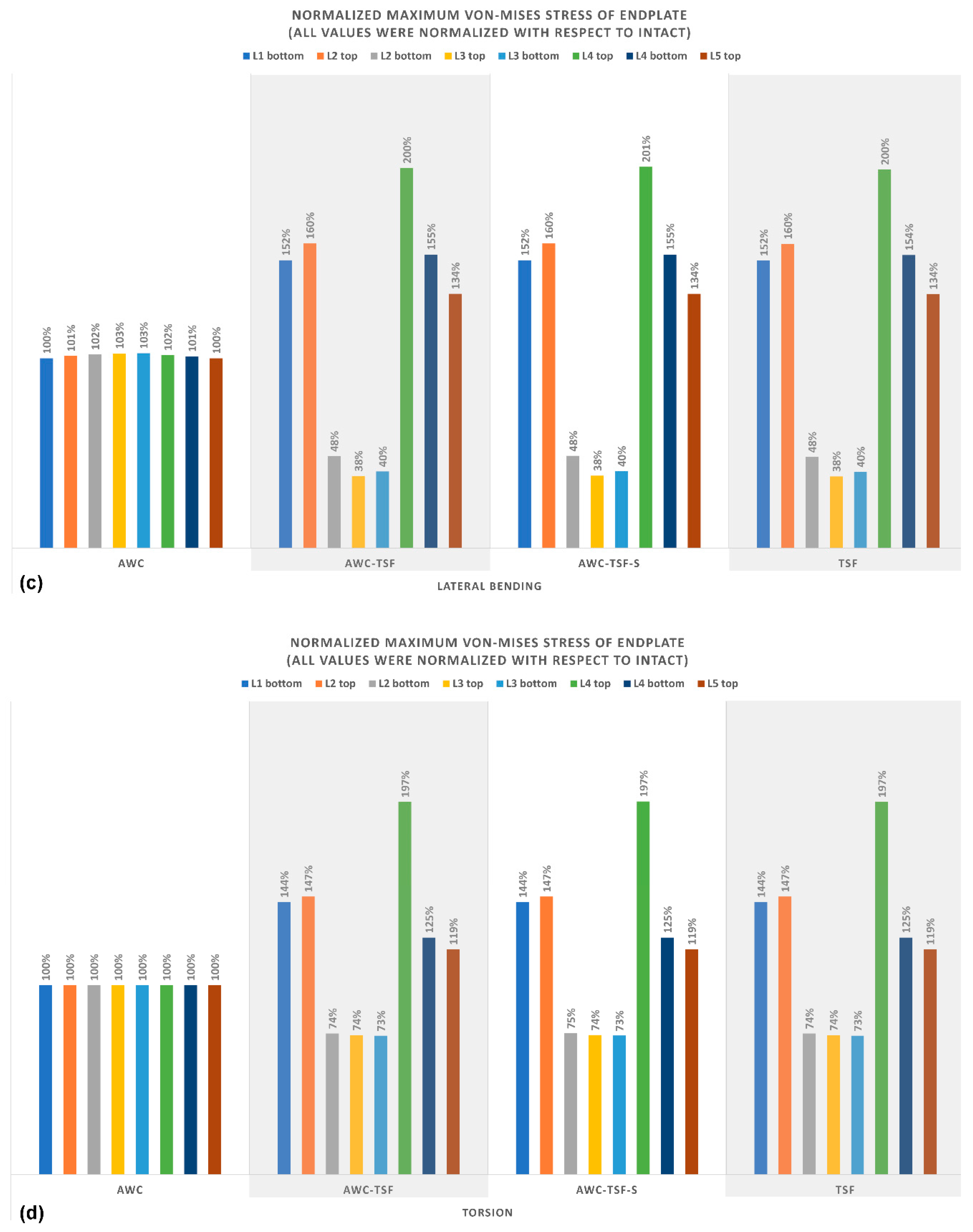
Figure 5 shows a clear reduction in stress on the endplate at the instrumented segments (AwC-TSF, AwC-TSF-S and TSF), in comparison to the INT model in all motion conditions. The maximum reduction in endplate stress (over 50% reduction) occurred at the instrumented segments (AwC-TSF, AwC-TSF-S and TSF) in lateral bending. The adjacent levels in AwC-TSF, AwC-TSF-S and TSF demonstrated a considerable increase in stress, with the maximum increase (over 200% increase over the INT model) occurring at the adjacent level (L5) of the instrumented models in flexion and extension. The endplate stress in the AwC model was similar to the INT model at each level.
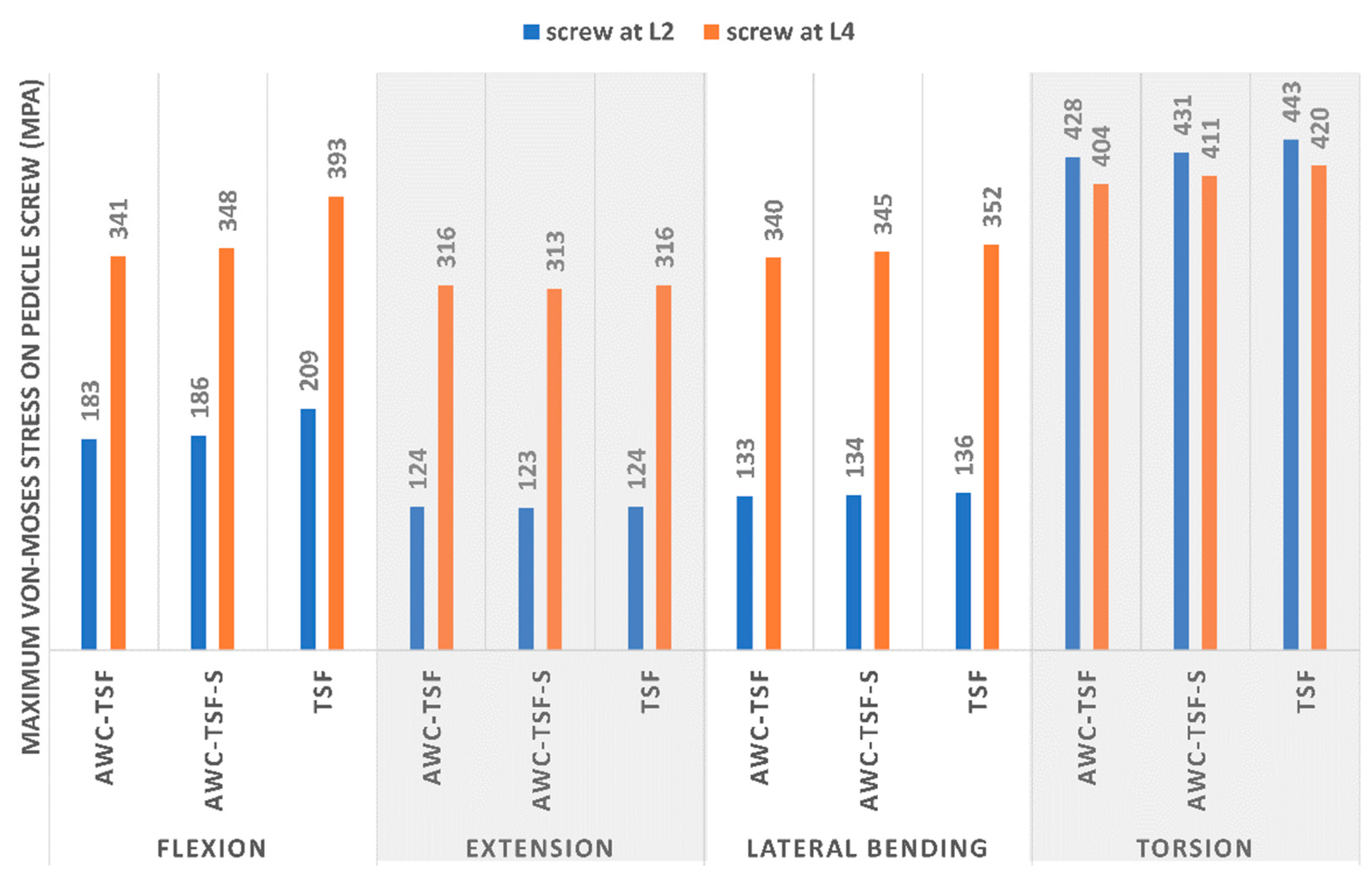
In the instrumented models, the maximum von Mises stress on the pedicle screws occurred at L2 in the TSF model in torsion (443 MPa), while the minimum stress occurred at L2 in the AwC-TSF-S model in extension (123 MPa), as shown in Figure 6.

4. Discussion

Vertebroplasty is often used to provide mechanical support to the anterior fractured column, thus reducing the rate of collapse. Wu et al. [15] reported on a fractured vertebral collapse treated with short segment fixation without vertebroplasty. In this current study, of all the instrumented models simulated, only the TSF model was not supplemented with vertebroplasty, which lead to a noticeable reduction in the flexion stiffness of the fixed segments. The models that combined vertebroplasty with posterior fixation demonstrated a considerable increase in the flexion stiffness of the fracture site, which could be reasonably expected to reduce the rate of vertebral collapse. Collapse of the greater anterior column would increase the loading and stress on pedicle screws or rods [22,23], and thus, the greatest von Mises stress was observed on the screws in the TSF model (i.e., without vertebroplasty) in flexion (Figure 6). In contrast, the maximum von Mises stress on the pedicle screws decreased considerably when the loading was shared by the fractured anterior column supplemented with bone cement (AwC-TSF and AwC-TSF-S models).
The range of motion of the instrumented segments in the AwC-TSF-S model was lower than in both the TSF and AwC-TSF models. The ROM is related to the displacement between the bone and screw in the bone tunnel, with the result that an increase in ROM means greater displacement or deformation at the bone–screw interface. The greater strain may lead to a “windshield wiper effect" with subsequent enlargement of the bone tunnel and eventual loosening of the graft [24,25]. Bostelmann et al. [24] reported that the use of cement-augmented screws significantly increased the number of load cycles achievable by the implanted segments in comparison to a non-augmented control group. In this current study, the AwC-TSF-S group had the lowest range of motion of the instrumented segments. The rigid anterior support and cement-augmented screws acted to reduce the migration of the bone–screw interface, which may slow the progression of screw loosening and screw cut out.
The stress on the adjacent discs in the AwC model was similar to the intact INT model. This is likely because the mobility of the motion segments is not affected by the cement injected into the vertebra during vertebroplasty. Of the instrumented models, the AwC-TSF-S model had the greatest increase in stress on the adjacent disc, which was primarily due to the increased stiffness of the motion segment due to the presence of the spinal implant [26,27,28,29].
These findings demonstrate that the increased stiffness of the motion segments resulted in greater stress on the adjacent disc (L1/L2 and L4/L5). As mentioned previously, the use of cement augmentation does not noticeably limit spinal motion, and as such, the use of cement-augmented pedicle screws would not induce greater loading on the discs in comparison to non-augmented screws. Therefore, the mobility of the adjacent segments was similar between AwC-TSF and AwC-TSF-S. Vertebroplasty also did not have much influence on the loading of adjacent segment discs after fixation with rigid instrumentation.
The maximum von Mises stress on the endplate of the AwC model was similar to the INT model, which is consistent with a study by Zhao et al. [30], and the von Mises stress on the adjacent vertebra was only slightly greater. In contrast, Cho et al. [13] indicated that augmentation with bone cement increases stress on the adjacent endplate. The results of this current study differ from those reported by Cho, possibly because of differences in spinal levels, lordotic angle and loading conditions. One critical difference is that Cho only created a 2-level spinal model, which is not large enough to incorporate a lordotic angle. Moreover, because the lordotic angle and augmented vertebral body height of the AwC model were the same as the intact model in this current study, this may also explain the relatively minor difference in stress on the adjacent endplate. The variation in stress on each endplate showed a similar trend for the TSF, AwC-TSF and AwC-TSF-S models under all motions. The presence of posterior pedicle screws (AwC-TSF, AwC-TSF-S and TSF) acted to decrease the maximum von Mises stress on the inferior endplate of L2 and the inferior/superior endplate of L3, while the stress increased on the inferior endplate of L1, superior endplate of L2, inferior endplate of L4 and superior endplate of L5. The use of cement-augmented screws (AwC-TSF-S) did not increase the stress on adjacent vertebrae. A biomechanical study by Aquarius et al. [31] showed that using clinically-relevant amounts of cement-augmentation did not lead to stress peaks under the endplate. It is therefore unlikely that bone cement alone would cause detrimental stresses on the adjacent vertebrae that could lead to vertebral fracture [32]. The results of this current study support the hypothesis that the use of cement-augmented screws (AwC-TSF-S) does not put the adjacent vertebrae at increased risk of fracture.
There are a number of limitations to this study that should be identified. Previous studies reported that the pull-out strength of screws is increased when augmented with cement [10,33], but the pull-out strength was not evaluated directly in this current study. Given the complexity of the physiological spine and variations in fracture types, the models simulated in this study were greatly simplified. Only a specific single-level burst fracture (L3) was simulated, and kyphotic spinal deformity or anterior column collapse were not considered in the unloaded condition; each group had the same angle of lumbar lordosis in the initial unloaded condition. The structure of the vertebral body was assumed to be isotropic and homogenous. The model also did not consider the mechanical effects of muscle contraction, so true physiological loading was not adopted in this analysis.
The complexity of the human spine and variations in material properties and boundary conditions makes it a suitable candidate for finite element modeling. Moreover, the finite element method often provides advantages where there are such individual variations, allowing cause–effect relationships to be isolated and fully explored.

5. Conclusions

The use of a hybrid fixation method combining vertebroplasty and cement-augmented screws for securing thoracolumbar burst fractures resulted in a stiffer construct and lower von Mises stress on the pedicle screws. The use of cement-augmented screw fixation (AwC-TSF-S) also decreased the ROM of the instrumented segments, possibly slowing the progression of screw loosening. This study showed that the use of cement-augmented screws does not put the adjacent vertebrae at increased risk of fracture. In summary, the hybrid fixation method presented in this study can better stabilize the spine and reduce the risk of implant failure.

Author Contributions

Conceptualization, Y.-Y.H., C.-H.C. and C.-J.C.; Methodology, Y.-Y.H., Y.-J.K. and L.-C.W.; Project administration, C.-J.C.; Resources, C.-H.C.; Software, L.-C.W.; Validation, Y.-J.K., C.-H.C., C.-J.C. and C.-L.L. – original draft, Y.-Y.H.; Writing – review & editing, Y.-J.K., C.-J.C. and C.-L.L. All authors have read and agreed to the published version of the manuscript.

Funding

This research received no external funding.

Conflicts of Interest

The authors declare no conflict of interest.

References

  1. Modi, H.; Chung, K.J.; Seo, I.W.; Yoon, H.S.; Hwang, J.H.; Kim, H.K.; Noh, K.C.; Yoo, J.H. Two levels above and one level below pedicle screw fixation for the treatment of unstable thoracolumbar fracture with partial or intact neurology. J. Orthop. Surg. Res. 2009, 4, 28. [Google Scholar] [CrossRef] [Green Version]
  2. Altay, M.; Ozkurt, B.; Aktekin, C.N.; Ozturk, A.M.; Doğan, Ö.; Tabak, A.Y. Treatment of unstable thoracolumbar junction burst fractures with short- or long-segment posterior fixation in magerl type a fractures. Eur. Spine J. 2007, 16, 1145–1155. [Google Scholar] [CrossRef] [Green Version]
  3. Guven, O.; Kocaoglu, B.; Bezer, M.; Aydin, N.; Nalbantoglu, U.; Kocaoglu, B. The Use of Screw at the Fracture Level in the Treatment of Thoracolumbar Burst Fractures. J. Spinal Disord. Tech. 2009, 22, 417–421. [Google Scholar] [CrossRef]
  4. McLain, R.F.; Sparling, E.; Benson, D.R. Early failure of short-segment pedicle instrumentation for thoracolumbar fractures. A preliminary report. J. Bone Jt. Surgery-American Vol. 1993, 75, 162–167. [Google Scholar] [CrossRef] [PubMed]
  5. Alanay, A.; Acaroğlu, E.; Yazici, M.; Oznur, A.; Surat, A. Short-Segment Pedicle Instrumentation of Thoracolumbar Burst Fractures. Spine 2001, 26, 213–217. [Google Scholar] [CrossRef] [PubMed]
  6. Knop, C.; Bastian, L.; Lange, U.; Oeser, M.; Zdichavsky, M.; Blauth, M. Complications in surgical treatment of thoracolumbar injuries. Eur. Spine J. 2002, 11, 214–226. [Google Scholar] [CrossRef] [PubMed] [Green Version]
  7. Jung, H.J.; Kim, S.W.; Ju, C.I.; Kim, S.H.; Kim, H.S. Bone Cement-Augmented Short Segment Fixation with Percutaneous Screws for Thoracolumbar Burst Fractures Accompanied by Severe Osteoporosis. J. Korean Neurosurg. Soc. 2012, 52, 353–358. [Google Scholar] [CrossRef] [PubMed]
  8. Kim, H.S.; Park, S.K.; Joy, H.; Ryu, J.K.; Kim, S.W.; Ju, C.I. Bone Cement Augmentation of Short Segment Fixation for Unstable Burst Fracture in Severe Osteoporosis. J. Korean Neurosurg. Soc. 2008, 44, 8–14. [Google Scholar] [CrossRef] [PubMed] [Green Version]
  9. Kim, H.S.; Kim, S.W.; Ju, C.I.; Lee, S.M.; Shin, H. Short Segment Fixation for Thoracolumbar Burst Fracture Accompanying Osteopenia: A Comparative Study. J. Korean Neurosurg. Soc. 2013, 53, 26–30. [Google Scholar] [CrossRef] [PubMed]
  10. Wittenberg, R.H.; Lee, K.-S.; Shea, M.; White, A.A.; Hayes, W.C. Effect of Screw Diameter, Insertion Technique, and Bone Cement Augmentation of Pedicular Screw Fixation Strength. Clin. Orthop. Relat. Res. 1993, 278–287. [Google Scholar] [CrossRef]
  11. Grados, F.; Depriester, C.; Cayrolle, G.; Hardy, N.; Deramond, H.; Fardellone, P. Long-term observations of vertebral osteoporotic fractures treated by percutaneous vertebroplasty. Rheumatol. 2000, 39, 1410–1414. [Google Scholar] [CrossRef] [Green Version]
  12. Uppin, A.A.; Hirsch, J.A.; Centenera, L.V.; Pfiefer, B.A.; Pazianos, A.G.; Choi, I.S. Occurrence of New Vertebral Body Fracture after Percutaneous Vertebroplasty in Patients with Osteoporosis1. Radiol. 2003, 226, 119–124. [Google Scholar] [CrossRef] [PubMed]
  13. Cho, A.-R.; Cho, S.-B.; Lee, J.-H.; Kim, K. Effect of Augmentation Material Stiffness on Adjacent Vertebrae after Osteoporotic Vertebroplasty Using Finite Element Analysis with Different Loading Methods. Pain Physician 2015, 18, E1101–E1110. [Google Scholar] [PubMed]
  14. Tropiano, P.; Huang, R.C.; Louis, C.A.; Poitout, D.G.; Louis, R.P. Functional and Radiographic Outcome of Thoracolumbar and Lumbar Burst Fractures Managed by Closed Orthopaedic Reduction and Casting. Spine 2003, 28, 2459–2465. [Google Scholar] [CrossRef] [PubMed]
  15. Wu, Y.; Chen, C.-H.; Tsuang, F.-Y.; Lin, Y.-C.; Chiang, C.-J.; Kuo, Y.-J. The stability of long-segment and short-segment fixation for treating severe burst fractures at the thoracolumbar junction in osteoporotic bone: A finite element analysis. PLoS ONE 2019, 14, e0211676. [Google Scholar] [CrossRef] [PubMed] [Green Version]
  16. Shih, S.-L.; Chen, C.-S.; Lin, H.-M.; Huang, L.-Y.; Liu, C.-L.; Huang, C.-H.; Cheng, C.-K. Effect of Spacer Diameter of the Dynesys Dynamic Stabilization System on the Biomechanics of the Lumbar Spine. J. Spinal Disord. Tech. 2012, 25, E119–E228. [Google Scholar] [CrossRef]
  17. Shih, S.-L.; Liu, C.-L.; Huang, L.-Y.; Huang, C.-H.; Chen, C.-S. Effects of cord pretension and stiffness of the Dynesys system spacer on the biomechanics of spinal decompression- a finite element study. BMC Musculoskelet. Disord. 2013, 14, 191. [Google Scholar] [CrossRef] [Green Version]
  18. Dreischarf, M.; Zander, T.; Shirazi-Adl, A.; Puttlitz, C.; Adam, C.; Chen, C.; Goel, V.; Kiapour, A.; Kim, Y.; Labus, K.; et al. Comparison of eight published static finite element models of the intact lumbar spine: Predictive power of models improves when combined together. J. Biomech. 2014, 47, 1757–1766. [Google Scholar] [CrossRef] [Green Version]
  19. Jamari, J.; Saputra, E.; Anwar, I.B.; Van Der Heide, E. Study of an Additional Layer of Cement Mantle Hip Joints for Reducing Cracks. J. Funct. Biomater. 2019, 10, 40. [Google Scholar] [CrossRef] [Green Version]
  20. Chen, H.-C.; Wu, J.-L.; Huang, S.-C.; Zhong, Z.-C.; Chiu, S.-L.; Lai, Y.-S.; Cheng, C.-K. Biomechanical evaluation of a novel pedicle screw-based interspinous spacer: A finite element analysis. Med Eng. Phys. 2017, 46, 27–32. [Google Scholar] [CrossRef]
  21. Panjabi, M.M. Hybrid multidirectional test method to evaluate spinal adjacent-level effects. Clin. Biomech. 2007, 22, 257–265. [Google Scholar] [CrossRef] [PubMed]
  22. Chen, C.-S.; Chen, W.-J.; Cheng, C.-K.; Jao, S.-H.E.; Chueh, S.-C.; Wang, C.-C. Failure analysis of broken pedicle screws on spinal instrumentation. Med Eng. Phys. 2005, 27, 487–496. [Google Scholar] [CrossRef] [PubMed]
  23. Mermelstein, L.E.; McLain, R.F.; Yerby, S.A. Reinforcement of thoracolumbar burst fractures with calcium phosphate cement: A biomechanical study. Spine 1998, 23, 664–671. [Google Scholar] [CrossRef]
  24. Bostelmann, R.; Keiler, A.; Steiger, H.J.; Scholz, A.; Cornelius, J.F.; Schmoelz, W. Effect of augmentation techniques on the failure of pedicle screws under cranio-caudal cyclic loading. Eur. Spine J. 2015, 26, 181–188. [Google Scholar] [CrossRef] [PubMed]
  25. Paik, H.; Dmitriev, A.E.; Lehman, R.A.; Gaume, R.E.; Ambati, D.V.; Kang, D.G.; Lenke, L.G. The biomechanical effect of pedicle screw hubbing on pullout resistance in the thoracic spine. Spine J. 2012, 12, 417–424. [Google Scholar] [CrossRef]
  26. Chen, C.-S.; Cheng, C.-K.; Liu, C.-L.; Lo, W.-H. Stress analysis of the disc adjacent to interbody fusion in lumbar spine. Med Eng. Phys. 2001, 23, 485–493. [Google Scholar] [CrossRef]
  27. Schlegel, J.D.; Smith, J.A.; Schleusener, R.L. Lumbar Motion Segment Pathology Adjacent to Thoracolumbar, Lumbar, and Lumbosacral Fusions. Spine 1996, 21, 970–981. [Google Scholar] [CrossRef]
  28. Park, P.; Garton, H.J.; Gala, V.C.; Hoff, J.T.; McGillicuddy, J.E. Adjacent Segment Disease after Lumbar or Lumbosacral Fusion: Review of the Literature. Spine 2004, 29, 1938–1944. [Google Scholar] [CrossRef]
  29. Hsieh, Y.-Y.; Chen, C.-H.; Tsuang, F.-Y.; Wu, L.-C.; Lin, S.-C.; Chiang, C.-J. Removal of fixation construct could mitigate adjacent segment stress after lumbosacral fusion: A finite element analysis. Clin. Biomech. 2017, 43, 115–120. [Google Scholar] [CrossRef] [Green Version]
  30. Zhao, W.-T.; Qin, D.-P.; Zhang, X.-G.; Wang, Z.-P.; Tong, Z. Biomechanical effects of different vertebral heights after augmentation of osteoporotic vertebral compression fracture: A three-dimensional finite element analysis. J. Orthop. Surg. Res. 2018, 13, 32. [Google Scholar] [CrossRef] [Green Version]
  31. Aquarius, R.; Van Der Zijden, A.; Homminga, J.; Verdonschot, N.; Tanck, E. Does Bone Cement In Percutaneous Vertebroplasty Act as a Stress Riser? Spine 2013, 38, 2092–2097. [Google Scholar] [CrossRef] [PubMed]
  32. Martín-Fernández, M.; López-Herradón, A.; Piñera, A.R.; Tomé-Bermejo, F.; Duart, J.; Vlad, M.; Rodríguez-Arguisjuela, M.; Alvarez-Galovich, L.; López-Herrradón, A. Potential risks of using cement-augmented screws for spinal fusion in patients with low bone quality. Spine J. 2017, 17, 1192–1199. [Google Scholar] [CrossRef] [PubMed]
  33. Fölsch, C.; Goost, H.; Figiel, J.; Paletta, J.R.; Schultz, W.; Lakemeier, S. Correlation of pull-out strength of cement-augmented pedicle screws with CT-volumetric measurement of cement. Biomed. Tech. Eng. 2012, 57, 73–80. [Google Scholar] [CrossRef] [PubMed]
Figure 1. Finite element model of the (a) intact (INT) lumbar spine implanted with (b) spinal posterior fixation system, cement augmentation at the L3 vertebra and (c) the cement-augmented pedicle screws at L2 and L4 in AwC-TSF-S. *The ligaments are: ALL, anterior longitudinal ligament; PLL, posterior longitudinal ligament; TL, transverse ligament; LF, ligamentum flavum; ISL, interspinous ligament; SSL, supraspinous ligament; CL, capsular ligament.
Applsci 10 02133 g001
Figure 2. (a) Range of motion of each motion segment in all implanted models, all values were normalized with respect to intact. (b) Method to determining the ROM (θ1 represent the ROM angle of L2-L3, θ2 represent the ROM angle of L3-L4); the cyan contour in solid line represent the lumbar segments after motion.
Applsci 10 02133 g002
Figure 3. Normalized stiffness of each model at L2–L4 segment in all implanted models.
Applsci 10 02133 g003
Figure 4. (a) Normalized maximum von Mises stress on the disc at each level in all implanted models. (b) von Mises stress distribution of the disc annulus under flexion for the INT and AwC-TSF-S models.
Applsci 10 02133 g004
Figure 5. Normalized maximum von Mises stress on the endplate at each level in (a) flexion, (b) extension, (c) lateral bending, and (d) torsion in all implanted models.
Applsci 10 02133 g005aApplsci 10 02133 g005b
Figure 6. Maximum von Mises stress on pedicle screws at L2 and L4.
Applsci 10 02133 g006
Table 1. The material properties of intact spine and instrumented models.
MaterialYoung’s Modulus (MPa)Poisson’s Ratio
Cortical bone [18]12,0000.2
Cancellous bone [18]300/1000.2
Annulus fibrous [18]Mooney–Rivlin
c1 = 0.18, c2 = 0.045
NA
Nucleus pulposus [18]Mooney–Rivlin
c1 = 0.12, c2 = 0.03
NA
Ligaments [18]Hyper-elasticNA
Bone Cement [19]23000.33
Pedicle screw (Titanium alloy) [20]113,0000.3
NA = not applicable.
Table 2. Range of motion (ROM) of all motion segments in five finite element (FE) models.
L1–L2L2–L3L3–L4L4–L5TOTAL ROMTorqueStiffness
DegreeNmNm/degree
FlexionINT3.933.943.895.3317.096.900.40
AwC3.973.863.815.3817.036.930.41
AwC-TSF6.171.621.267.9817.0412.500.73
AwC-TSF-S6.301.531.188.0617.0713.200.77
TSF6.141.681.337.8617.0111.740.69
ExtensionINT2.802.392.252.219.656.900.71
AwC2.802.392.252.219.656.900.71
AwC-TSF3.770.780.574.539.6510.851.12
AwC-TSF-S3.870.740.544.559.7011.701.21
TSF3.770.810.604.449.6110.561.10
Lateral BendingINT3.303.172.982.8812.335.100.41
AwC3.273.203.012.8512.335.110.41
AwC-TSF5.080.960.705.3312.087.870.65
AwC-TSF-S5.160.920.675.3612.118.400.69
TSF5.060.990.745.2812.067.440.62
TorsionINT1.952.212.593.6310.389.300.90
AwC1.942.222.603.6110.389.320.90
AwC-TSF2.271.652.194.2610.3712.171.17
AwC-TSF-S2.291.592.114.3510.3413.201.28
TSF2.211.702.294.1610.3611.711.13
Table 3. Maximum von Mises stress in disc and endplate in five FE models.
Maximum Disc von-Mises Stress (MPa)Maximum von Mises Stress of Endplate (kPa)
L1-L2L2-L3L3-L4L4-L5L1 bottomL2 topL2 bottomL3 topL3 bottomL4 topL4 bottomL5 top
values were normalized with respect to INT.values were normalized with respect to INT.
FlexionINT89276964976658504760508040204900419058505580
AwC102%99%100%105%100%101%103%103%104%103%102%100%
AwC-TSF157%84%84%172%183%190%86%74%77%130%189%232%
AwC-TSF-S158%90%87%174%186%193%83%72%74%126%192%237%
TSF157%84%84%171%182%189%85%73%76%129%189%232%
ExtensionINT47337538332136504170352036402310318019402310
AwC100%100%100%100%100%100%100%100%100%100%100%100%
AwC-TSF122%57%43%160%139%136%78%72%81%102%169%227%
AwC-TSF-S124%59%44%164%139%136%79%73%81%103%169%227%
TSF122%57%42%159%139%136%78%72%81%102%169%227%
Lateral BendingINT66565160753645103720433036703980307039903820
AwC100%101%101%100%100%101%102%103%103%102%101%100%
AwC-TSF152%48%41%167%152%160%48%38%40%200%155%134%
AwC-TSF-S156%46%39%171%152%160%48%38%40%201%155%134%
TSF150%47%40%164%152%160%48%38%40%200%154%134%
TorsionINT33630633755834202970330025803300275043304110
AwC100%100%98%100%100%100%100%100%100%100%100%100%
AwC-TSF112%100%99%119%144%147%74%74%73%197%125%119%
AwC-TSF-S114%100%101%121%144%147%75%74%73%197%125%119%
TSF112%100%99%119%144%147%74%74%73%197%125%119%