Biomechanical Assessment of Vertebroplasty Combined with Cement-Augmented Screw Fixation for Lumbar Burst Fractures: A Finite Element Analysis

 , , and
Abstract
:1. Introduction
2. Materials and Methods
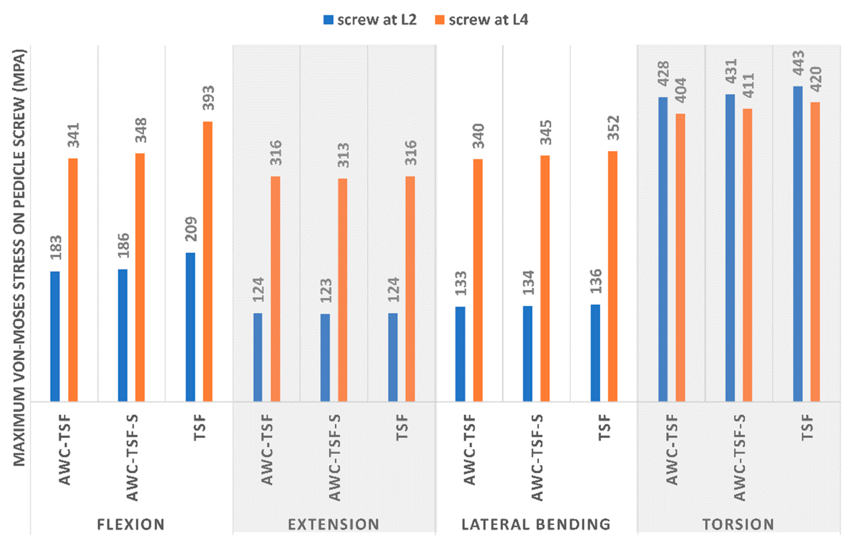
3. Results
4. Discussion
5. Conclusions
Author Contributions
Funding
Conflicts of Interest
References
- Modi, H.; Chung, K.J.; Seo, I.W.; Yoon, H.S.; Hwang, J.H.; Kim, H.K.; Noh, K.C.; Yoo, J.H. Two levels above and one level below pedicle screw fixation for the treatment of unstable thoracolumbar fracture with partial or intact neurology. J. Orthop. Surg. Res. 2009, 4, 28. [Google Scholar] [CrossRef] [Green Version]
- Altay, M.; Ozkurt, B.; Aktekin, C.N.; Ozturk, A.M.; Doğan, Ö.; Tabak, A.Y. Treatment of unstable thoracolumbar junction burst fractures with short- or long-segment posterior fixation in magerl type a fractures. Eur. Spine J. 2007, 16, 1145–1155. [Google Scholar] [CrossRef] [Green Version]
- Guven, O.; Kocaoglu, B.; Bezer, M.; Aydin, N.; Nalbantoglu, U.; Kocaoglu, B. The Use of Screw at the Fracture Level in the Treatment of Thoracolumbar Burst Fractures. J. Spinal Disord. Tech. 2009, 22, 417–421. [Google Scholar] [CrossRef]
- McLain, R.F.; Sparling, E.; Benson, D.R. Early failure of short-segment pedicle instrumentation for thoracolumbar fractures. A preliminary report. J. Bone Jt. Surgery-American Vol. 1993, 75, 162–167. [Google Scholar] [CrossRef] [PubMed]
- Alanay, A.; Acaroğlu, E.; Yazici, M.; Oznur, A.; Surat, A. Short-Segment Pedicle Instrumentation of Thoracolumbar Burst Fractures. Spine 2001, 26, 213–217. [Google Scholar] [CrossRef] [PubMed]
- Knop, C.; Bastian, L.; Lange, U.; Oeser, M.; Zdichavsky, M.; Blauth, M. Complications in surgical treatment of thoracolumbar injuries. Eur. Spine J. 2002, 11, 214–226. [Google Scholar] [CrossRef] [PubMed] [Green Version]
- Jung, H.J.; Kim, S.W.; Ju, C.I.; Kim, S.H.; Kim, H.S. Bone Cement-Augmented Short Segment Fixation with Percutaneous Screws for Thoracolumbar Burst Fractures Accompanied by Severe Osteoporosis. J. Korean Neurosurg. Soc. 2012, 52, 353–358. [Google Scholar] [CrossRef] [PubMed]
- Kim, H.S.; Park, S.K.; Joy, H.; Ryu, J.K.; Kim, S.W.; Ju, C.I. Bone Cement Augmentation of Short Segment Fixation for Unstable Burst Fracture in Severe Osteoporosis. J. Korean Neurosurg. Soc. 2008, 44, 8–14. [Google Scholar] [CrossRef] [PubMed] [Green Version]
- Kim, H.S.; Kim, S.W.; Ju, C.I.; Lee, S.M.; Shin, H. Short Segment Fixation for Thoracolumbar Burst Fracture Accompanying Osteopenia: A Comparative Study. J. Korean Neurosurg. Soc. 2013, 53, 26–30. [Google Scholar] [CrossRef] [PubMed]
- Wittenberg, R.H.; Lee, K.-S.; Shea, M.; White, A.A.; Hayes, W.C. Effect of Screw Diameter, Insertion Technique, and Bone Cement Augmentation of Pedicular Screw Fixation Strength. Clin. Orthop. Relat. Res. 1993, 278–287. [Google Scholar] [CrossRef]
- Grados, F.; Depriester, C.; Cayrolle, G.; Hardy, N.; Deramond, H.; Fardellone, P. Long-term observations of vertebral osteoporotic fractures treated by percutaneous vertebroplasty. Rheumatol. 2000, 39, 1410–1414. [Google Scholar] [CrossRef] [Green Version]
- Uppin, A.A.; Hirsch, J.A.; Centenera, L.V.; Pfiefer, B.A.; Pazianos, A.G.; Choi, I.S. Occurrence of New Vertebral Body Fracture after Percutaneous Vertebroplasty in Patients with Osteoporosis1. Radiol. 2003, 226, 119–124. [Google Scholar] [CrossRef] [PubMed]
- Cho, A.-R.; Cho, S.-B.; Lee, J.-H.; Kim, K. Effect of Augmentation Material Stiffness on Adjacent Vertebrae after Osteoporotic Vertebroplasty Using Finite Element Analysis with Different Loading Methods. Pain Physician 2015, 18, E1101–E1110. [Google Scholar] [PubMed]
- Tropiano, P.; Huang, R.C.; Louis, C.A.; Poitout, D.G.; Louis, R.P. Functional and Radiographic Outcome of Thoracolumbar and Lumbar Burst Fractures Managed by Closed Orthopaedic Reduction and Casting. Spine 2003, 28, 2459–2465. [Google Scholar] [CrossRef] [PubMed]
- Wu, Y.; Chen, C.-H.; Tsuang, F.-Y.; Lin, Y.-C.; Chiang, C.-J.; Kuo, Y.-J. The stability of long-segment and short-segment fixation for treating severe burst fractures at the thoracolumbar junction in osteoporotic bone: A finite element analysis. PLoS ONE 2019, 14, e0211676. [Google Scholar] [CrossRef] [PubMed] [Green Version]
- Shih, S.-L.; Chen, C.-S.; Lin, H.-M.; Huang, L.-Y.; Liu, C.-L.; Huang, C.-H.; Cheng, C.-K. Effect of Spacer Diameter of the Dynesys Dynamic Stabilization System on the Biomechanics of the Lumbar Spine. J. Spinal Disord. Tech. 2012, 25, E119–E228. [Google Scholar] [CrossRef]
- Shih, S.-L.; Liu, C.-L.; Huang, L.-Y.; Huang, C.-H.; Chen, C.-S. Effects of cord pretension and stiffness of the Dynesys system spacer on the biomechanics of spinal decompression- a finite element study. BMC Musculoskelet. Disord. 2013, 14, 191. [Google Scholar] [CrossRef] [Green Version]
- Dreischarf, M.; Zander, T.; Shirazi-Adl, A.; Puttlitz, C.; Adam, C.; Chen, C.; Goel, V.; Kiapour, A.; Kim, Y.; Labus, K.; et al. Comparison of eight published static finite element models of the intact lumbar spine: Predictive power of models improves when combined together. J. Biomech. 2014, 47, 1757–1766. [Google Scholar] [CrossRef] [Green Version]
- Jamari, J.; Saputra, E.; Anwar, I.B.; Van Der Heide, E. Study of an Additional Layer of Cement Mantle Hip Joints for Reducing Cracks. J. Funct. Biomater. 2019, 10, 40. [Google Scholar] [CrossRef] [Green Version]
- Chen, H.-C.; Wu, J.-L.; Huang, S.-C.; Zhong, Z.-C.; Chiu, S.-L.; Lai, Y.-S.; Cheng, C.-K. Biomechanical evaluation of a novel pedicle screw-based interspinous spacer: A finite element analysis. Med Eng. Phys. 2017, 46, 27–32. [Google Scholar] [CrossRef]
- Panjabi, M.M. Hybrid multidirectional test method to evaluate spinal adjacent-level effects. Clin. Biomech. 2007, 22, 257–265. [Google Scholar] [CrossRef] [PubMed]
- Chen, C.-S.; Chen, W.-J.; Cheng, C.-K.; Jao, S.-H.E.; Chueh, S.-C.; Wang, C.-C. Failure analysis of broken pedicle screws on spinal instrumentation. Med Eng. Phys. 2005, 27, 487–496. [Google Scholar] [CrossRef] [PubMed]
- Mermelstein, L.E.; McLain, R.F.; Yerby, S.A. Reinforcement of thoracolumbar burst fractures with calcium phosphate cement: A biomechanical study. Spine 1998, 23, 664–671. [Google Scholar] [CrossRef]
- Bostelmann, R.; Keiler, A.; Steiger, H.J.; Scholz, A.; Cornelius, J.F.; Schmoelz, W. Effect of augmentation techniques on the failure of pedicle screws under cranio-caudal cyclic loading. Eur. Spine J. 2015, 26, 181–188. [Google Scholar] [CrossRef] [PubMed]
- Paik, H.; Dmitriev, A.E.; Lehman, R.A.; Gaume, R.E.; Ambati, D.V.; Kang, D.G.; Lenke, L.G. The biomechanical effect of pedicle screw hubbing on pullout resistance in the thoracic spine. Spine J. 2012, 12, 417–424. [Google Scholar] [CrossRef]
- Chen, C.-S.; Cheng, C.-K.; Liu, C.-L.; Lo, W.-H. Stress analysis of the disc adjacent to interbody fusion in lumbar spine. Med Eng. Phys. 2001, 23, 485–493. [Google Scholar] [CrossRef]
- Schlegel, J.D.; Smith, J.A.; Schleusener, R.L. Lumbar Motion Segment Pathology Adjacent to Thoracolumbar, Lumbar, and Lumbosacral Fusions. Spine 1996, 21, 970–981. [Google Scholar] [CrossRef]
- Park, P.; Garton, H.J.; Gala, V.C.; Hoff, J.T.; McGillicuddy, J.E. Adjacent Segment Disease after Lumbar or Lumbosacral Fusion: Review of the Literature. Spine 2004, 29, 1938–1944. [Google Scholar] [CrossRef]
- Hsieh, Y.-Y.; Chen, C.-H.; Tsuang, F.-Y.; Wu, L.-C.; Lin, S.-C.; Chiang, C.-J. Removal of fixation construct could mitigate adjacent segment stress after lumbosacral fusion: A finite element analysis. Clin. Biomech. 2017, 43, 115–120. [Google Scholar] [CrossRef] [Green Version]
- Zhao, W.-T.; Qin, D.-P.; Zhang, X.-G.; Wang, Z.-P.; Tong, Z. Biomechanical effects of different vertebral heights after augmentation of osteoporotic vertebral compression fracture: A three-dimensional finite element analysis. J. Orthop. Surg. Res. 2018, 13, 32. [Google Scholar] [CrossRef] [Green Version]
- Aquarius, R.; Van Der Zijden, A.; Homminga, J.; Verdonschot, N.; Tanck, E. Does Bone Cement In Percutaneous Vertebroplasty Act as a Stress Riser? Spine 2013, 38, 2092–2097. [Google Scholar] [CrossRef] [PubMed]
- Martín-Fernández, M.; López-Herradón, A.; Piñera, A.R.; Tomé-Bermejo, F.; Duart, J.; Vlad, M.; Rodríguez-Arguisjuela, M.; Alvarez-Galovich, L.; López-Herrradón, A. Potential risks of using cement-augmented screws for spinal fusion in patients with low bone quality. Spine J. 2017, 17, 1192–1199. [Google Scholar] [CrossRef] [PubMed]
- Fölsch, C.; Goost, H.; Figiel, J.; Paletta, J.R.; Schultz, W.; Lakemeier, S. Correlation of pull-out strength of cement-augmented pedicle screws with CT-volumetric measurement of cement. Biomed. Tech. Eng. 2012, 57, 73–80. [Google Scholar] [CrossRef] [PubMed]


| Material | Young’s Modulus (MPa) | Poisson’s Ratio |
|---|---|---|
| Cortical bone [18] | 12,000 | 0.2 |
| Cancellous bone [18] | 300/100 | 0.2 |
| Annulus fibrous [18] | Mooney–Rivlin c1 = 0.18, c2 = 0.045 | NA |
| Nucleus pulposus [18] | Mooney–Rivlin c1 = 0.12, c2 = 0.03 | NA |
| Ligaments [18] | Hyper-elastic | NA |
| Bone Cement [19] | 2300 | 0.33 |
| Pedicle screw (Titanium alloy) [20] | 113,000 | 0.3 |
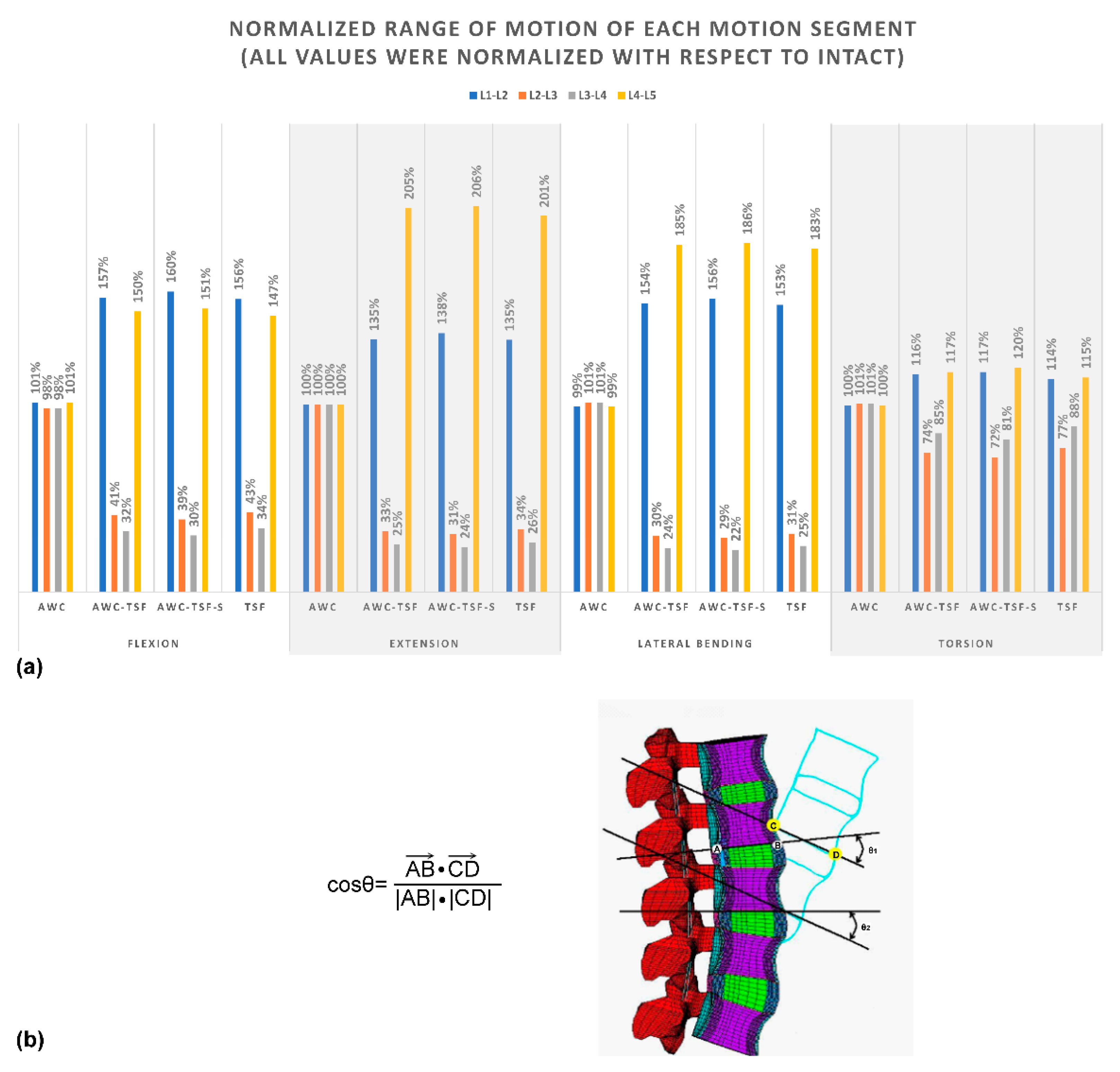
| L1–L2 | L2–L3 | L3–L4 | L4–L5 | TOTAL ROM | Torque | Stiffness | ||
|---|---|---|---|---|---|---|---|---|
| Degree | Nm | Nm/degree | ||||||
| Flexion | INT | 3.93 | 3.94 | 3.89 | 5.33 | 17.09 | 6.90 | 0.40 |
| AwC | 3.97 | 3.86 | 3.81 | 5.38 | 17.03 | 6.93 | 0.41 | |
| AwC-TSF | 6.17 | 1.62 | 1.26 | 7.98 | 17.04 | 12.50 | 0.73 | |
| AwC-TSF-S | 6.30 | 1.53 | 1.18 | 8.06 | 17.07 | 13.20 | 0.77 | |
| TSF | 6.14 | 1.68 | 1.33 | 7.86 | 17.01 | 11.74 | 0.69 | |
| Extension | INT | 2.80 | 2.39 | 2.25 | 2.21 | 9.65 | 6.90 | 0.71 |
| AwC | 2.80 | 2.39 | 2.25 | 2.21 | 9.65 | 6.90 | 0.71 | |
| AwC-TSF | 3.77 | 0.78 | 0.57 | 4.53 | 9.65 | 10.85 | 1.12 | |
| AwC-TSF-S | 3.87 | 0.74 | 0.54 | 4.55 | 9.70 | 11.70 | 1.21 | |
| TSF | 3.77 | 0.81 | 0.60 | 4.44 | 9.61 | 10.56 | 1.10 | |
| Lateral Bending | INT | 3.30 | 3.17 | 2.98 | 2.88 | 12.33 | 5.10 | 0.41 |
| AwC | 3.27 | 3.20 | 3.01 | 2.85 | 12.33 | 5.11 | 0.41 | |
| AwC-TSF | 5.08 | 0.96 | 0.70 | 5.33 | 12.08 | 7.87 | 0.65 | |
| AwC-TSF-S | 5.16 | 0.92 | 0.67 | 5.36 | 12.11 | 8.40 | 0.69 | |
| TSF | 5.06 | 0.99 | 0.74 | 5.28 | 12.06 | 7.44 | 0.62 | |
| Torsion | INT | 1.95 | 2.21 | 2.59 | 3.63 | 10.38 | 9.30 | 0.90 |
| AwC | 1.94 | 2.22 | 2.60 | 3.61 | 10.38 | 9.32 | 0.90 | |
| AwC-TSF | 2.27 | 1.65 | 2.19 | 4.26 | 10.37 | 12.17 | 1.17 | |
| AwC-TSF-S | 2.29 | 1.59 | 2.11 | 4.35 | 10.34 | 13.20 | 1.28 | |
| TSF | 2.21 | 1.70 | 2.29 | 4.16 | 10.36 | 11.71 | 1.13 | |
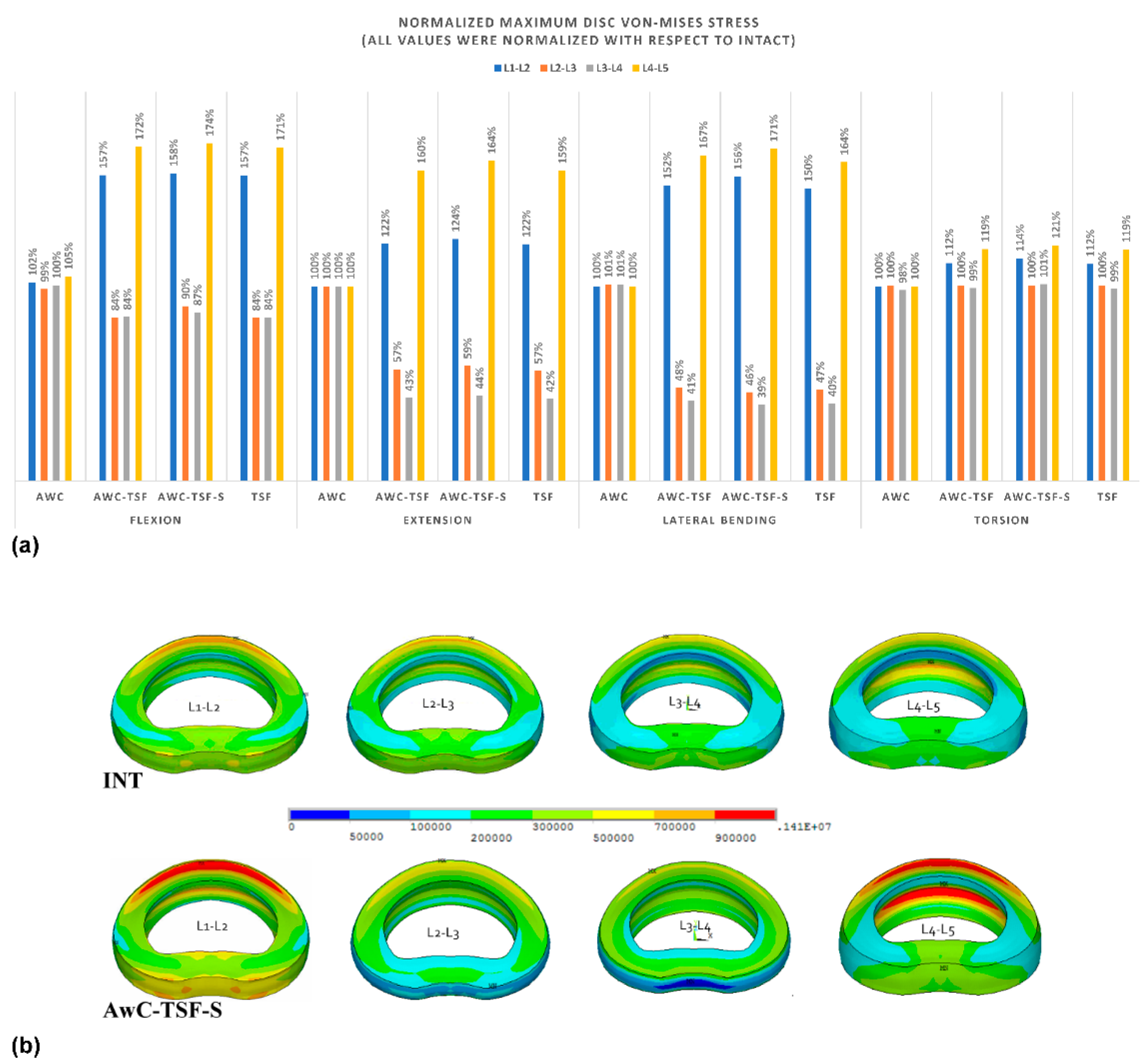
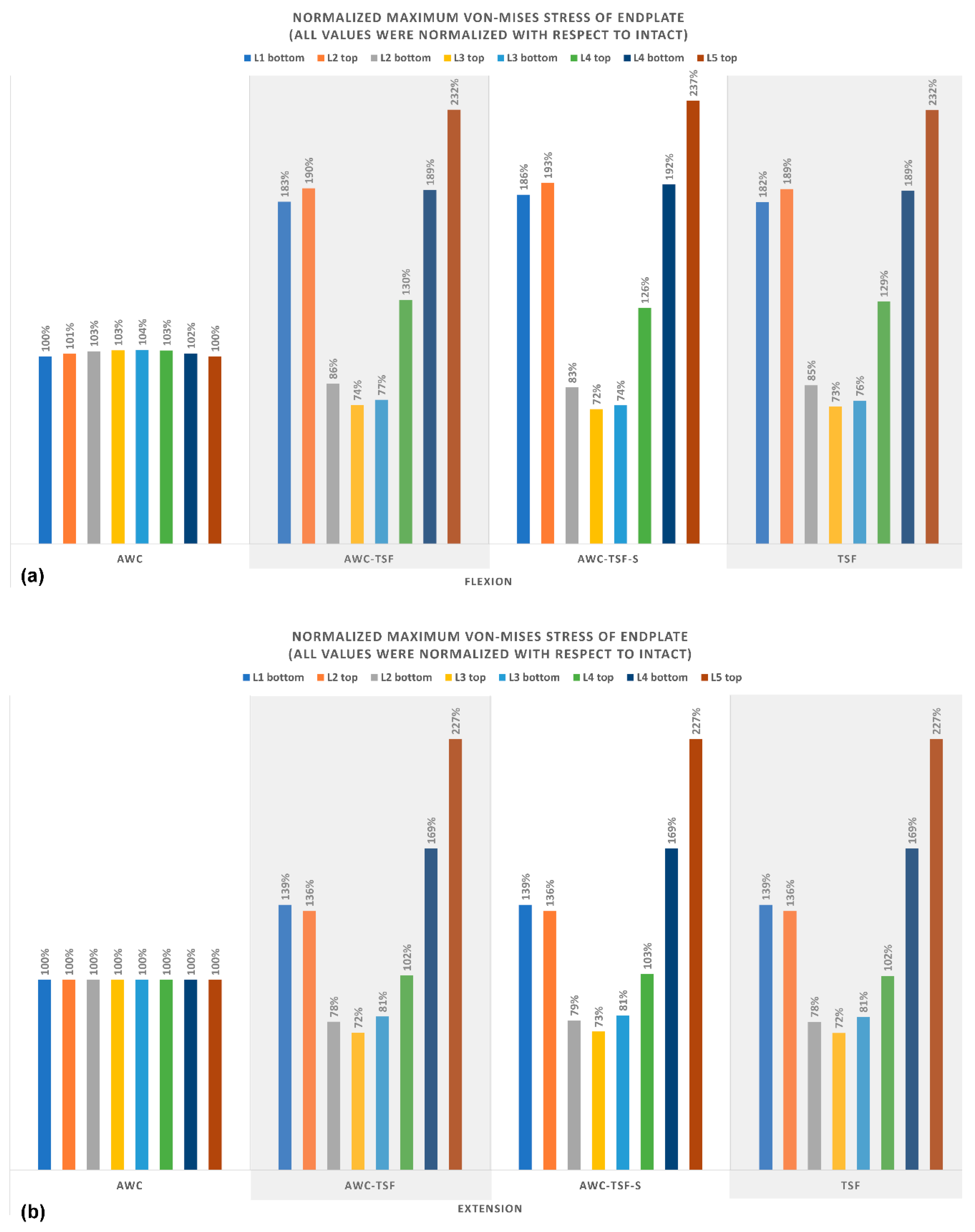
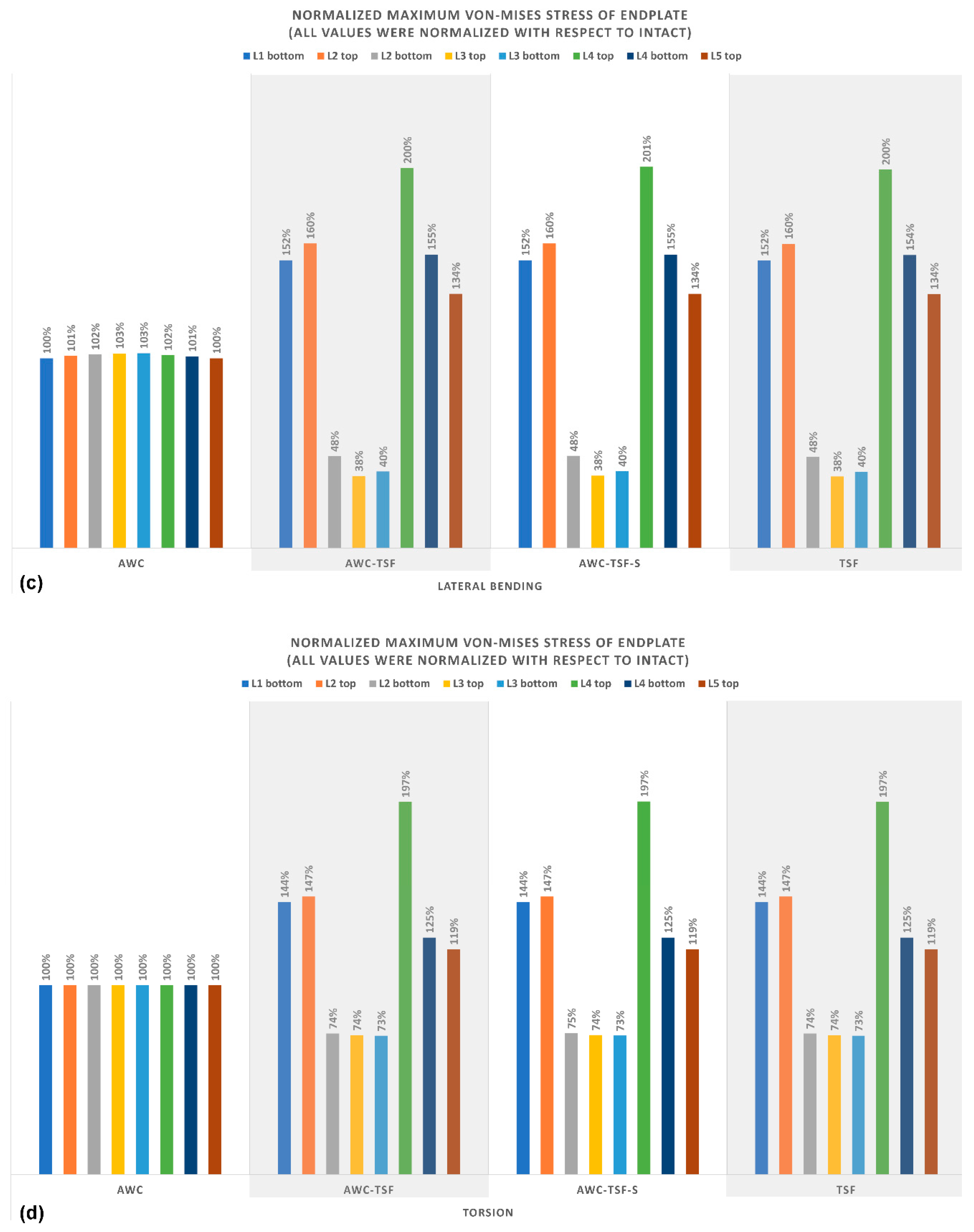
| Maximum Disc von-Mises Stress (MPa) | Maximum von Mises Stress of Endplate (kPa) | ||||||||||||
|---|---|---|---|---|---|---|---|---|---|---|---|---|---|
| L1-L2 | L2-L3 | L3-L4 | L4-L5 | L1 bottom | L2 top | L2 bottom | L3 top | L3 bottom | L4 top | L4 bottom | L5 top | ||
| values were normalized with respect to INT. | values were normalized with respect to INT. | ||||||||||||
| Flexion | INT | 892 | 769 | 649 | 766 | 5850 | 4760 | 5080 | 4020 | 4900 | 4190 | 5850 | 5580 |
| AwC | 102% | 99% | 100% | 105% | 100% | 101% | 103% | 103% | 104% | 103% | 102% | 100% | |
| AwC-TSF | 157% | 84% | 84% | 172% | 183% | 190% | 86% | 74% | 77% | 130% | 189% | 232% | |
| AwC-TSF-S | 158% | 90% | 87% | 174% | 186% | 193% | 83% | 72% | 74% | 126% | 192% | 237% | |
| TSF | 157% | 84% | 84% | 171% | 182% | 189% | 85% | 73% | 76% | 129% | 189% | 232% | |
| Extension | INT | 473 | 375 | 383 | 321 | 3650 | 4170 | 3520 | 3640 | 2310 | 3180 | 1940 | 2310 |
| AwC | 100% | 100% | 100% | 100% | 100% | 100% | 100% | 100% | 100% | 100% | 100% | 100% | |
| AwC-TSF | 122% | 57% | 43% | 160% | 139% | 136% | 78% | 72% | 81% | 102% | 169% | 227% | |
| AwC-TSF-S | 124% | 59% | 44% | 164% | 139% | 136% | 79% | 73% | 81% | 103% | 169% | 227% | |
| TSF | 122% | 57% | 42% | 159% | 139% | 136% | 78% | 72% | 81% | 102% | 169% | 227% | |
| Lateral Bending | INT | 665 | 651 | 607 | 536 | 4510 | 3720 | 4330 | 3670 | 3980 | 3070 | 3990 | 3820 |
| AwC | 100% | 101% | 101% | 100% | 100% | 101% | 102% | 103% | 103% | 102% | 101% | 100% | |
| AwC-TSF | 152% | 48% | 41% | 167% | 152% | 160% | 48% | 38% | 40% | 200% | 155% | 134% | |
| AwC-TSF-S | 156% | 46% | 39% | 171% | 152% | 160% | 48% | 38% | 40% | 201% | 155% | 134% | |
| TSF | 150% | 47% | 40% | 164% | 152% | 160% | 48% | 38% | 40% | 200% | 154% | 134% | |
| Torsion | INT | 336 | 306 | 337 | 558 | 3420 | 2970 | 3300 | 2580 | 3300 | 2750 | 4330 | 4110 |
| AwC | 100% | 100% | 98% | 100% | 100% | 100% | 100% | 100% | 100% | 100% | 100% | 100% | |
| AwC-TSF | 112% | 100% | 99% | 119% | 144% | 147% | 74% | 74% | 73% | 197% | 125% | 119% | |
| AwC-TSF-S | 114% | 100% | 101% | 121% | 144% | 147% | 75% | 74% | 73% | 197% | 125% | 119% | |
| TSF | 112% | 100% | 99% | 119% | 144% | 147% | 74% | 74% | 73% | 197% | 125% | 119% | |
© 2020 by the authors. Licensee MDPI, Basel, Switzerland. This article is an open access article distributed under the terms and conditions of the Creative Commons Attribution (CC BY) license (http://creativecommons.org/licenses/by/4.0/).
Share and Cite
Hsieh, Y.-Y.; Kuo, Y.-J.; Chen, C.-H.; Wu, L.-C.; Chiang, C.-J.; Lin, C.-L. Biomechanical Assessment of Vertebroplasty Combined with Cement-Augmented Screw Fixation for Lumbar Burst Fractures: A Finite Element Analysis. Appl. Sci. 2020, 10, 2133. https://doi.org/10.3390/app10062133
Hsieh Y-Y, Kuo Y-J, Chen C-H, Wu L-C, Chiang C-J, Lin C-L. Biomechanical Assessment of Vertebroplasty Combined with Cement-Augmented Screw Fixation for Lumbar Burst Fractures: A Finite Element Analysis. Applied Sciences. 2020; 10(6):2133. https://doi.org/10.3390/app10062133
Chicago/Turabian StyleHsieh, Yueh-Ying, Yi-Jie Kuo, Chia-Hsien Chen, Lien-Chen Wu, Chang-Jung Chiang, and Chun-Li Lin. 2020. "Biomechanical Assessment of Vertebroplasty Combined with Cement-Augmented Screw Fixation for Lumbar Burst Fractures: A Finite Element Analysis" Applied Sciences 10, no. 6: 2133. https://doi.org/10.3390/app10062133