Article

Estimation of Hand Motion from Piezoelectric Soft Sensor Using Deep Recurrent Network

1
Center for Intelligent and Interactive Robotics, Korea Institute of Science and Technology, Seoul 02792, Korea
2
Department of Mechanical Engineering, Soongsil University, Seoul 07040, Korea
*
Authors to whom correspondence should be addressed.
Appl. Sci. 2020, 10(6), 2194; https://doi.org/10.3390/app10062194
Submission received: 21 February 2020 / Revised: 20 March 2020 / Accepted: 20 March 2020 / Published: 24 March 2020
(This article belongs to the Special Issue Flexible Piezoelectric Materials)

Abstract

:
Soft sensors are attracting significant attention in human–machine interaction due to their high flexibility and adaptability. However, estimating motion state from these sensors is difficult due to their nonlinearity and noise. In this paper, we propose a deep learning network for a smart glove system to predict the moving state of a piezoelectric soft sensor. We implemented the network using Long-Short Term Memory (LSTM) units and demonstrated its performance in a real-time system based on two experiments. The sensor’s moving state was estimated and the joint angles were calculated. Since we use moving state in the sensor offset calculation and the offset value is used to estimate the angle value, the accurate moving state estimation results in good performance for angle value estimation. The proposed network performed better than the conventional heuristic method in estimating the moving state. It was also confirmed that the calculated values successfully mimic the joint angles measured using a leap motion controller.

1. Introduction

In recent years, human–machine interaction techniques have been spotlighted in robotics research. For human–machine interaction, accurate representation of the human body state is important. In studies on human motion recognition, various sensors are used to measure human body states [1,2]. In particular, soft sensors have received significant attention with respect to human–machine interaction and are applied to many wearable applications due to their high flexibility and adaptability [3,4,5].
The raw data acquired from various sensors need to be appropriately processed to be used in a motion state estimation. However, if the sensor has a nonlinear characteristic, it is hard to analyze or utilize. To solve this problem, recent studies have proposed the use of networks using deep learning to predict the nonlinear correlation [6,7,8,9]. Given that the soft sensor has higher nonlinear characteristics compared to traditional sensors [10], deep learning has been applied to characterize soft sensors and motion recognition in [11,12,13].
Among the various soft sensors, those made of piezoelectric materials are well suited for human–machine interactions in wearable devices [14,15] due to their flexibility associated with micro-scale thickness, low power, and convenience in installation [16,17]. In our previous studies, we demonstrated the performance of smart gloves using flexible piezoelectric sensors and demonstrated the interaction ability of these gloves in virtual reality applications [18,19]. Apart from these advantages, piezoelectric sensors exhibit high nonlinearity and noise similar to other soft sensors. In this study, we adopted deep learning as a method to address this problem. Specifically, the offsets of piezoelectric sensors were randomly changed in addition to the nonlinearly in a real-time system. Since we follow the offset value only in the case that the sensor does not move, the accuracy of the sensor offset value is related to the estimation of the moving state. At the same time, the angle value is calculated using the sensor offset value. This means that a good estimation of the moving state leads to a good result for angle estimation. Thus, we propose a network to predict the moving state for stabilization of the offset value. Moreover, we incorporated the trained network into the interface system for the smart glove to recognize hand joint angles.
Given that our goal is to apply the proposed network to a the real-time virtual reality interaction system, we designed it to be suitable for processing sequential data at high speed. In the proposed network, sequential sensor data, which are analog voltages, are used as the input data. We introduce the structure of the network using the Long-Short Term Memory (LSTM) units for predicting outputs and utilized the estimated result in our glove system. Several previous studies have already used the LSTM unit for processing of sequential sensor data [11,12,20,21] and the performance of the network was demonstrated.
Training of the network was conducted using a leap motion controller as the ground-truth data. The moving state, the target data for training, was defined with the measured angle value, which means that if the value is 1, the sensor is in moving state and static when value is 0. The performance of the network was demonstrated by two different experiments, with pre-acquired datasets and using a real-time interface system with a smart glove. We evaluated the accuracy of network predictions using our training and test dataset. In addition, the performance of the network for real-time application was evaluated using two criteria, an identical ratio of moving states and the similarity of the joint angles. An overview of the proposed system is shown in Figure 1.
Our major contributions are as follows: (i) proposing a deep recurrent network that is trained by the novel input data, piezoelectric soft sensor; (ii) applying the proposed network into the real-time VR interface system; and (iii) showing the improvement of performance by applying deep learning into sensor data processing compared to our prior works.
This paper is organized into the following sections. In Section 2, we introduce the interface system used for the smart glove. In Section 3, we propose and evaluate the deep learning network for sensor data processing. We demonstrate the performance of the real-time application of network in Section 4. Section 5 is a brief summary of the main conclusions.

2. Interface System

Herein, we introduce the interface system used to receive signals from the smart glove and to calculate the joint angles of the hand motion using a piezoelectric voltage.

2.1. Glove Structure

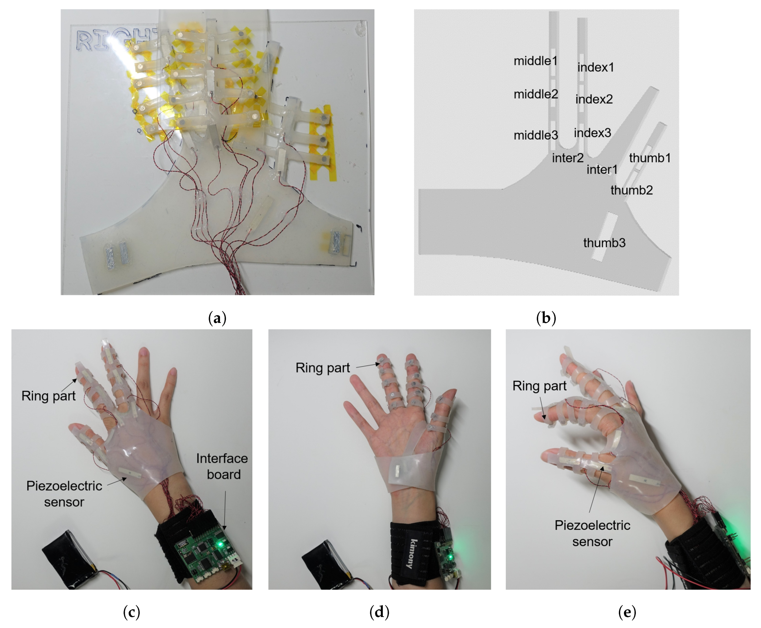
In our previous studies [18,19], data from the fabricated sensor were received by an interface board. In this study, we use the same interface board and piezoelectric sensors proposed in previous works. Especially, the sensor used in this study is proposed in [18]. A PVDF film was used to generate a piezoelectric effect, and the sensor was fabricated with a uniform beam structure with thin PVDF and Mylar layers. Detailed information on the structure of the interface board and sensor is outlined in [18]. Different from previous works, we changed the structure of the glove and interface program. The entire glove, including the main component and ring component, was fabricated using Ecoflex 00-30 silicone rubber. The new design improves the flexibility of the glove and wear sensation. Specifically, we fabricated the ring part using several lines that were combined with the straight-finger section of the glove. Small neodymium magnets were included at the end of the ring component and they were linked to each other to form a closed loop. The structure of the glove and the position of the sensors are shown in Figure 2a,b and an image of the glove being worn with the caption of each part is shown in Figure 2c–e.

2.2. System Setup

In this study, we need to simultaneously acquire and process data from two different sensors: a piezoelectric sensor and the leap motion controller. The piezoelectric sensor data are our main interest to be trained, and the data from the leap motion controller are used as the ground-truth data for training. Thus, we programmed the interface to implement two virtual hands, as shown in Figure 3. The virtual hand located on the left side was implemented based on finger joint angles estimated by the piezoelectric sensors, and the right hand shows joint angles measured directly using a leap motion controller. The detail process of angle calculation is reviewed in Section 3. Given that the proposed program received two kinds of sensor data, it was necessary to synchronize the data. The data acquisition rate of the piezoelectric sensor is 100 Hz, while the rate of the leap motion controller is 60 Hz. Therefore, the leap motion values were synchronized to the piezoelectric sensor outputs using the following approximation.
θ l ( t n ) = θ l ( t k 1 ( l ) ) + ( θ l ( t k ( l ) ) θ l ( t k 1 ( l ) ) ) × t n t k 1 ( l ) t k ( l ) t k 1 ( l )
where θ l ( t n ) is the angle at the time of interest t n , θ l ( t k ( l ) ) is the raw data from the leap motion controller, and t k ( l ) is time of leap motion controller data at kth order, for the condition t k 1 ( l ) t n < t k ( l ) .
In addition, the offset voltage applied to the sensor from the interface board is 2.5 V. This voltage is changed when the piezoelectric voltage is generated from the piezoelectric sensor. The range of the analog voltage transferred to the system from the interface board is 0–5 V.

3. Application of Recurrent Network

In this section, we propose the deep recurrent network to process the piezoelectric sensor data. To make a network that works well with the input sensor data, we need to know about the characterization of sensor data. In addition, to train the network with good performance, input data and the ground-truth data should be well defined. Therefore, we explain our motion recognition method and discuss the characterization of the piezoelectric sensor. Afterwards, we discuss how to obtain sensor data for the training. Finally, the structure of the proposed network using two different recurrent units, RNN and LSTM, is introduced, and the performance between two units is compared.

3.1. Conventional Angle Recognition Method

In our previous study, we used the following relationship between the curvature and the voltage of the piezoelectric sensor [22]:
q ( t ) = C v ( t ) + ϵ k ¯ ( t ) ,
q ˙ ( t ) = v ( t ) R l o a d ,
where q is the charge stored in the piezoelectric sensor, C is capacitance, v is the piezoelectric voltage, ϵ is electromechanical coupling coefficient, k ¯ is the mean curvature, and R l o a d is the load resistance.
Applying the Laplace transformation, Equations (2) and (3) can be written as:
Q ( s ) = C V ( s ) + ϵ K ¯ ( s ) ,
s Q ( s ) = V ( s ) R l o a d ,
in the s domain.
Inserting Equation (4) into Equation (5) by substituting for Q ( s ) , we have:
s · ( C V ( s ) + ϵ K ¯ ( s ) ) = V ( s ) R l o a d .
By reorganizing Equation (6) as the relation between K ( s ) and V ( s ) , we have:
ϵ K ¯ ( s ) = 1 + s · C · R l o a d s · R l o a d V ( s ) .
When the piezoelectric sensor has low capacitance value and load resistance value ( 1 > > C · R l o a d ), Equation (7) reduces to:
ϵ K ¯ ( s ) 1 s · R l o a d V ( s ) .
Equation (8) can be expressed as follows in the time domain after implementing the inverse-Laplace transform:
ϵ k ¯ ( t ) 1 R l o a d · 0 t v ( τ ) d τ .
In the beam structure, the value of the mean curvature is related to the change of the slope between the start and end of the beam, and the slope can be expressed as the angle of the sensor [22]. From these relations, we derive the following equation using the angular change of the sensor and piezoelectric voltage [18]:
θ ( t n ) = a × m = 1 n v t m O t m × Δ t m n = 1 , 2 , . . .
where θ is the angle variation of the piezoelectric sensor, A is the gain including all proportional terms, O is the offset, Δ t m is the time interval, and t n = m = 1 n Δ t m .

3.2. Estimation of Moving State and Offset Voltage

Assigning t = 0 in Equation (9), v ( 0 ) is determined with the initial value of mean curvature k ¯ ( 0 ) . This means that, if k ¯ ( 0 ) is nonzero, there is a voltage offset. Ideally, the mean curvature is zero at the original position. However, it is difficult to achieve zero mean curvature in a real case. In addition, given that a finger moves continuously in real-time experiment, the initial mean value can have small variation when it comes back to the original position. The difference between original position and varied position also affects the offset value.
As shown in Figure 4, calculation of joint angle values using improper offsets results in incorrect results. If v ( t m ) is the same as the O ( t m ) , as shown in Figure 4a, the joint angle is calculated normally. However, if there is a difference between the estimated offset and real offset of the raw data, as shown in Figure 4b,c, the error ( v ( t m ) O ( t m ) ) is integrated as the time Δ t m . Therefore, the selection of an appropriate offset voltage value is an important issue. In [18], we defined the offset value O a as the average of 3000 data, such that:
O a ( t n ) = m = n 2999 n v ( t m ) 3000 .
Using the average value is a reasonable choice for following the tendency of the signal. However, the average value can oscillate when data having a large difference are entered, and a slight offset change is applied slowly. To solve this problem, we determined the offset voltage with voltages for non-movement to update k ¯ ( 0 ) in [19]. Assuming only curvature change of the sensor results in significant change of piezoelectric voltage sensor, the heuristic moving state m h is estimated as follows:
m h ( t n ) = 0 , | Δ v ( t n ) | < v t h 1 , | Δ v ( t n ) | v t h
Δ v ( t n ) = v ( t n ) v ( t n 1 ) .
where v t h is the threshold voltage for deciding the moving state. We consider the finger as moving when m h ( t n ) = 1 and stopped when m h ( t n ) = 0 . This method can continuously renew offset change that occurs via variation of k ¯ ( 0 ) faster than previous one. However, heuristic moving state estimation of Equation (12) confronts following problems in a real-time system:
  • If noise is added to v, it is hard to distinguish noise from curvature change.
  • Input noise can be random value in case that the system is operated in different environment.
  • When noise is random, v t h is hard to determine.
For these reasons, it is difficult to estimate m h in noisy environment. Therefore, we propose a network to train a moving state using recurrent neural networks as alternative.

3.3. Data Acquisition

For network training, we need the dataset including the input data and the ground-truth target data which need to be predicted. In this study, we extracted the ground-truth moving state from the finger joint angle measured by leap motion controller. Different from other vision sensors, the leap motion controller facilitates the direct acquisition of the finger joint angle without additional processing. Although the measured angle from the leap motion controller exhibits differences in the real joint angle, as compared to Chophuk et al. [23], we chose the leap motion controller as a ground-truth sensor due to its characteristic and because it can facilitate large dataset generation.
To obtain a dataset for learning, we conducted an experiment using the interface mentioned in Section 2. For data acquisition, we set up the experiment as follows:
  • We used the soft sensor located on the glove, and its piezoelectric voltage was measured with the interface board.
  • Joint angle for acquiring moving state was simultaneously measured with leap motion controller.
  • Single movement was composed with flexion and extension.
  • The range of flexion angle was determined randomly between 30 degrees and 90 degrees.
  • Movements for training set were conducted 1080 times, and those for the test set were conducted 270 times.
The decision of the moving state m g t is given by:
m g t ( t n ) = 0 , | k = n 9 n θ ( t k ) 10 θ ( t n ) | < Δ θ t h 1 , e l s e ,
where Δ θ t h is the threshold angle variation. We assumed that the finger is moving when the difference between the average of 10 recent values and the new value is larger than V t h . We selected Δ θ t h as 2 degrees based on preliminary tests.
Figure 5 displays the sample of the dataset acquired from the experiment. The network was trained using the input data in Figure 5a to estimate the moving state in Figure 5c.
Since our goal was to extract real-time moving state with using piezoelectric sensor outputs, we preprocessed the piezoelectric voltage into sequential input data X ( t n ) = [ x ( t n 9 ) , . . . , x ( t n ) ] using the sliding window method, where
x ( t n ) = [ v ( t n ) , v ˙ ( t n ) ] ,
v ˙ ( t n ) = v ( t n ) v ( t n 1 ) t n t n 1 .
In addition, we defines target data of the network as y ( t n ) = m g t ( t n ) . Summaries of the processed training and test sets are shown in Table 1.

3.4. Proposed Network

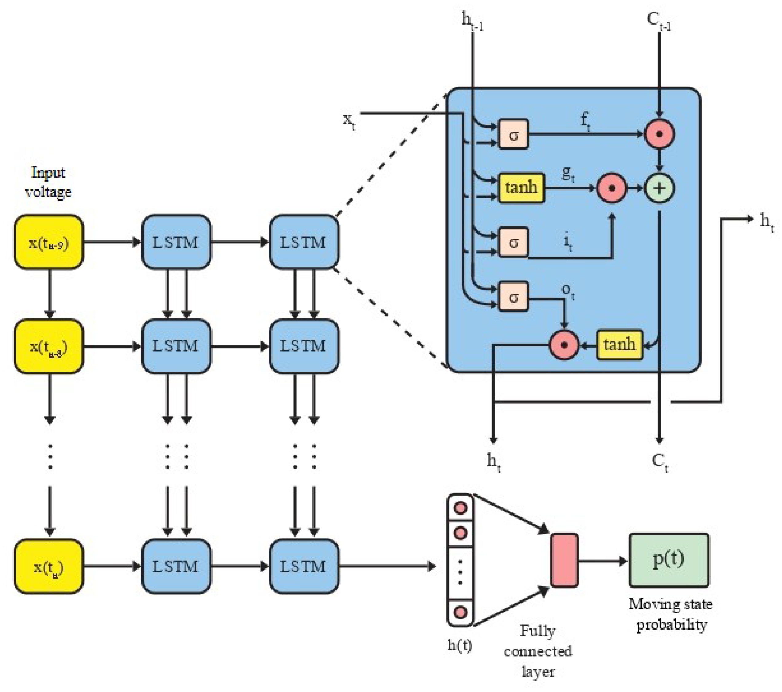
To train the moving state of the sensor, we used a recurrent neural network (RNN), which is appropriate for training a sequential dataset. Using input vector x t and previous hidden state h t , a simple RNN determines the hidden state as follows:
h t = tanh ( x t W x + h t 1 W h + b ) ,
where W h , W x , and b are the network parameters.
Given that hidden state h t is determined with previous hidden state h t 1 , simple RNN can contain sequential information based on the recurrent hidden state. However, when the length of the data becomes larger, the gradient vanishes and explodes. To solve the problem and transfer the hidden layer information deeper, Long Short-Term Memory is proposed in [24]. Using cell vector c t and several gates, the hidden state h t is calculated as follows:
f t = σ ( x t W x ( f ) + h t 1 W h ( f ) + b ( f ) ) ,
g t = tanh ( x t W x ( g ) + h t 1 W h ( g ) + b ( g ) ) ,
i t = σ ( x t W x ( i ) + h t 1 W h ( i ) + b ( i ) ) ,
o t = σ ( x t W x ( o ) + h t 1 W h ( o ) + b ( o ) ) ,
c t = f c t 1 + g t i
h t = o tanh ( c t )
where i t , f t , and o t are input gate, forget gate, and output gate vector, respectively; g t and h t are cell input and output activation functions; W and b denote weight matrices and bias vector of the network; ⊙ is the element-wise product of the vectors; and tanh is output activation function. h t of LSTM unit can save more sequential information than h t of simple RNN unit. The network size of LSTM is four times larger than RNN. We applied both recurrent units into the proposed network and compared the performance.
To implement the real-time moving state estimation, we propose the network as shown in Figure 6. At each time step t n , X ( t n ) passes two recurrent layers and produces the hidden layer h ( t n ) , which contains the sequential information of X ( t n ) . To convert the sequential information into a single moving state, the fully connected layer combines the information of h ( t n ) and determines the final output. Given that state 1 refers to moving and 0 refers to stopping, the final output of the network p ( t n ) states the probability of moving. Therefore, we define the predicted moving state m p ( t n ) = [ p ( t n ) ] .
We trained the network for 100 epochs and used stochastic gradient descent (SGD) as the optimizer. In addition, we applied a dropout layer after the final recurrent layer at a rate of 50% rate in training to avoid overfitting.
As the recurrent unit, we used simple RNN and LSTM units and compared the result. Table 2 displays the result for accuracy of the training set and test set for both methods.
From the result, the model using LSTM unit exhibited slightly higher accuracy for the test and training set. In addition, the test accuracy of the model using the LSTM unit is more consistent than that of the model using simple RNN. The result indicates that only simple substitution for the recurrent unit without network structure change results in performance improvement in the proposed network. As stated in [25], there exists a modeling weakness of a simple RNN structure, and the LSTM structure is used to overcome the vanishing error [24,26]. The vanishing of the error gradient is increased when the long-term dependencies of input–output are enlarged. it means the LSTM unit can transfer the error information deeply than the RNN unit during the training when the training data includes long recurrent time steps. Since the single training data of our work include 10-time steps of sensor data, the LSTM unit can transfer the information deeply than the simple RNN unit when training the network. Therefore, we conclude that the LSTM unit is better suited than the simple RNN unit for soft sensor characterization, and chose the LSTM unit for the proposed network.

4. Result and Discussion

We evaluated our model using a real-time glove system. The experiment was conducted with an interface and the system stated in Section 2. Two experiments were conducted in this study. We initially demonstrated network performance in real-time moving state estimation and established the validity of network application for joint angle calculation. To estimate moving states m p of each joint, we utilized the network proposed in Section 3.4 and estimated the moving state with all X from different sensors received by interface board. For calculation of the joint angle, we updated the offset values using m p and calculated angle degrees for all the sensor locations.
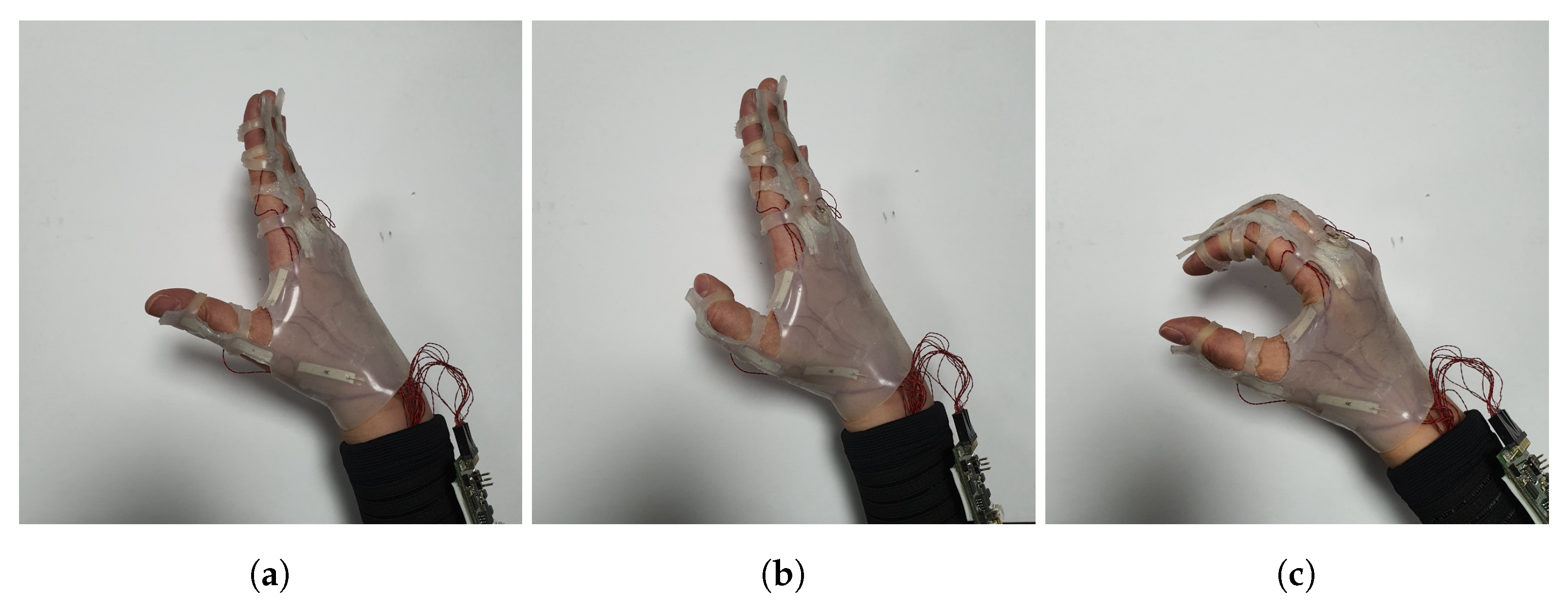
Bending thumb and clenching fist motion except for the thumb were selected as experimental motions. The motions are shown in Figure 7. Each motion was performed five times for one test. Using the thumb bending motion, the three sensors installed in the thumb, thumb1, thumb2, and thumb3, were evaluated. The sensors installed in the index finger, index1, index2, and index3, were evaluated using the motion clenching fist except the thumb. Experiments were conducted 80 times for moving state estimation and 50 times for angle value calculation.

4.1. Moving State Estimation

To evaluate the performance of the proposed network, we compared the result m p with m h from Equation (14). Table 3 shows an identical ratio of m p and m h with m g t . In Table 3, it is evident that the coincidence between m p and m g t is 5–25% higher than the coincidence between m h and m g t . This shows that the predicted m p is more similar to the ground-truth data than m h . In addition, while m h confuses curvature change with noise, as shown in Figure 8d, the result in Figure 8c shows that m p rarely confuses noise with sensor movement and recognizes only sensor movement.
Based on this result, we demonstrate that the network exhibits good performance for moving state estimation in real-time, multiple sensor data as single pre-acquired data. The result indicates that the proposed network can also predict moving state in real-time system, and chasing k ¯ ( 0 ) for offset renewing in a real-time system is also facilitated with the proposed network.

4.2. Angle Value Estimation

Based on good network performance for predicting m p , we show the ability for joint angle estimation by utilizing m p in this subsection. For demonstration, we compared the result for the methods used in our earlier studies [18,19]. In [18], we assumed that the offset O a as average value of sensor data without using moving state. In [19], we estimated the moving state heuristically and determined the offset O h . In this experiment, we assumed that the offset values were determined for the predicted moving state O p , as the average of the recent 200 data for m p = 0 .
For joint angle calculation, we applied offsets O a , O h , and O p in Equation (10). The calculated joint angles were compared to the joint angles measured by the leap motion controller, and the criteria are defined as the difference between the degrees.
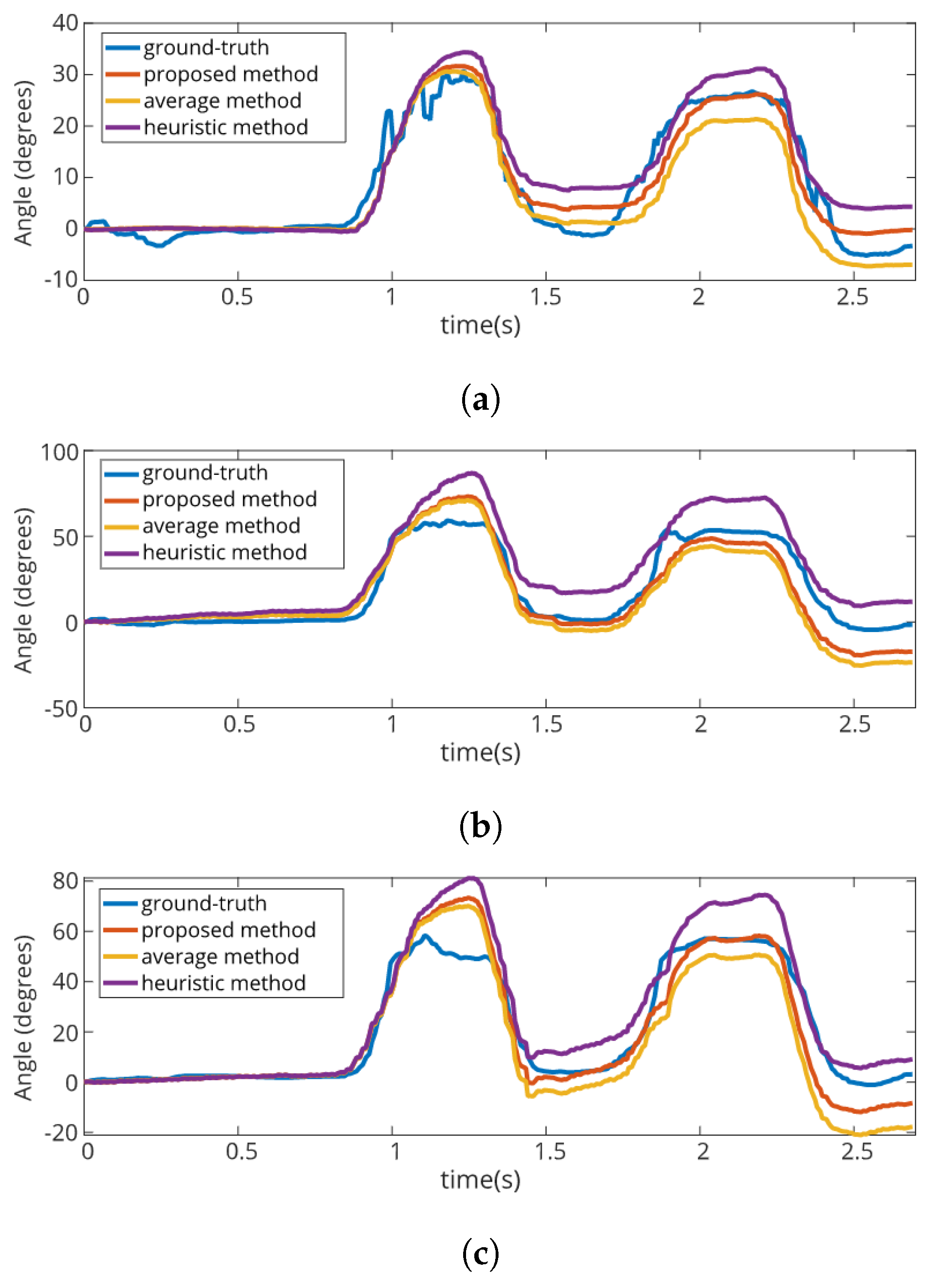
Table 4 shows the average values of the angle difference in degrees between the joint angle from the leap motion controller and the calculated joint angles. Table 5 shows the standard deviation of the degree difference for each location. Figure 9 and Figure 10 show the graph for examples of angle value comparisons between the joint angles in each location.
From the results, the averages and standard deviations for degree differences facilitate the lowest value of the joint angle calculated using O p . In addition, as shown in Figure 9 and Figure 10, the angle estimation based on the proposed method shows the most similar value compared to the ground-truth data. The result demonstrates that a good estimation of the moving state leads to a good result for angle estimation. One notable result is the joint angle calculated using O h is very stable occasionally but does not always exhibit good result for angle estimation compared to using O a . This means that incorrect estimation of the moving state can lead to poor results for angle estimation. Therefore, we demonstrate the importance of precise estimation of moving state via two results: good estimation of joint angle using O p and some estimation of joint angle using O h .

5. Conclusions

In this paper, we propose a virtual reality interface system with a smart glove system using a deep learning network to predict the moving state of piezoelectric soft sensors. To predict the nonlinear characteristic of sequential sensor data, we use LSTM as the recurrent unit of the proposed network. This network predicted the moving state of a single soft sensor with 87% accuracy on the test dataset and in excess of 80% accuracy with real-time, multiple data. In addition, the joint angle calculated using the proposed method has shown the best similarity to leap motion controller compared to the other methods. Based on the result, we concluded that deep learning can be applied to the inference of the piezoelectric sensor characteristic in a real-time system. In addition, precise estimation of the sensor moving state affects the estimation of the joint angles in real-time application. For future works, we will apply deep learning networks to other systems using piezoelectric sensors and broaden the prediction of feature of these sensors.

Author Contributions

S.H.K. and Y.K. performed the experiment. S.H.K. programmed the sensing system. Y.K. contributed to the setup of the experiment. S.H.K., K.K. and Y.C. analyzed the data and wrote the paper. All authors have read and agreed to the published version of the manuscript.

Funding

This work was supported by the Korea Institute of Science and Technology flagship program (Project No. 2E30280).

Conflicts of Interest

The authors declare no conflict of interest.

Abbreviations

The following abbreviations are used in this manuscript:
LSTMLong-Short Term Memory
RNNRecurrenct Neural Network
SGDStochastic Gradient Descent

References

  1. Yang, C.C.; Hsu, Y.L. A review of accelerometry-based wearable motion detectors for physical activity monitoring. Sensors 2010, 10, 7772–7788. [Google Scholar] [CrossRef]
  2. Liu, Y.; Nie, L.; Liu, L.; Rosenblum, D.S. From action to activity: Sensor-based activity recognition. Neurocomputing 2016, 181, 108–115. [Google Scholar] [CrossRef]
  3. Yap, H.K.; Lim, J.H.; Nasrallah, F.; Goh, J.C.; Yeow, R.C. A soft exoskeleton for hand assistive and rehabilitation application using pneumatic actuators with variable stiffness. In Proceedings of the 2015 IEEE International Conference on Robotics and Automation (ICRA), Seattle, WA, USA, 26–30 May 2015; IEEE: Piscatawa, NJ, USA, 2015; pp. 4967–4972. [Google Scholar]
  4. Polygerinos, P.; Wang, Z.; Galloway, K.C.; Wood, R.J.; Walsh, C.J. Soft robotic glove for combined assistance and at-home rehabilitation. Robot. Auton. Syst. 2015, 73, 135–143. [Google Scholar] [CrossRef] [Green Version]
  5. Mengüç, Y.; Park, Y.L.; Pei, H.; Vogt, D.; Aubin, P.M.; Winchell, E.; Fluke, L.; Stirling, L.; Wood, R.J.; Walsh, C.J. Wearable soft sensing suit for human gait measurement. Int. J. Robot. Res. 2014, 33, 1748–1764. [Google Scholar] [CrossRef]
  6. Wang, J.; Chen, Y.; Hao, S.; Peng, X.; Hu, L. Deep learning for sensor-based activity recognition: A survey. Pattern Recognit. Lett. 2019, 119, 3–11. [Google Scholar] [CrossRef] [Green Version]
  7. Chen, Y.; Xue, Y. A deep learning approach to human activity recognition based on single accelerometer. In Proceedings of the 2015 IEEE International Conference on Systems, Man, and Cybernetics, Kowloon, Hong Kong, China, 9–12 October 2015; IEEE: Piscatawa, NJ, USA, 2015; pp. 1488–1492. [Google Scholar]
  8. Kim, Y.; Toomajian, B. Hand gesture recognition using micro-Doppler signatures with convolutional neural network. IEEE Access 2016, 4, 7125–7130. [Google Scholar] [CrossRef]
  9. Pourbabaee, B.; Roshtkhari, M.J.; Khorasani, K. Deep convolutional neural networks and learning ECG features for screening paroxysmal atrial fibrillation patients. IEEE Trans. Syst. Man Cybern. Syst. 2017, 48, 2095–2104. [Google Scholar] [CrossRef]
  10. Park, Y.L.; Tepayotl-Ramirez, D.; Wood, R.J.; Majidi, C. Influence of cross-sectional geometry on the sensitivity and hysteresis of liquid-phase electronic pressure sensors. Appl. Phys. Lett. 2012, 101, 191904. [Google Scholar] [CrossRef] [Green Version]
  11. Han, S.; Kim, T.; Kim, D.; Park, Y.L.; Jo, S. Use of deep learning for characterization of microfluidic soft sensors. IEEE Robot. Autom. Lett. 2018, 3, 873–880. [Google Scholar] [CrossRef]
  12. Kim, D.; Kwon, J.; Han, S.; Park, Y.L.; Jo, S. Deep Full-Body Motion Network for a Soft Wearable Motion Sensing Suit. IEEE/ASME Trans. Mechatron. 2018, 24, 56–66. [Google Scholar] [CrossRef]
  13. Yuan, W.; Zhu, C.; Owens, A.; Srinivasan, M.A.; Adelson, E.H. Shape-independent hardness estimation using deep learning and a gelsight tactile sensor. In Proceedings of the 2017 IEEE International Conference on Robotics and Automation (ICRA), Singapore, 29 May–3 June 2017; IEEE: Piscatawa, NJ, USA, 2017; pp. 951–958. [Google Scholar]
  14. Dong, W.; Xiao, L.; Hu, W.; Zhu, C.; Huang, Y.; Yin, Z. Wearable human–machine interface based on PVDF piezoelectric sensor. Trans. Inst. Meas. Control. 2017, 39, 398–403. [Google Scholar] [CrossRef]
  15. Swallow, L.; Luo, J.; Siores, E.; Patel, I.; Dodds, D. A piezoelectric fibre composite based energy harvesting device for potential wearable applications. Smart Mater. Struct. 2008, 17. [Google Scholar] [CrossRef]
  16. Wang, Y.; Zheng, J.; Ren, G.; Zhang, P.; Xu, C. A flexible piezoelectric force sensor based on PVDF fabrics. Smart Mater. Struct. 2011, 20. [Google Scholar] [CrossRef]
  17. Akiyama, M.; Morofuji, Y.; Kamohara, T.; Nishikubo, K.; Tsubai, M.; Fukuda, O.; Ueno, N. Flexible piezoelectric pressure sensors using oriented aluminum nitride thin films prepared on polyethylene terephthalate films. J. Appl. Phys. 2006, 100, 114318. [Google Scholar] [CrossRef]
  18. Cha, Y.; Seo, J.; Kim, J.S.; Park, J.M. Human–computer interface glove using flexible piezoelectric sensors. Smart Mater. Struct. 2017, 26. [Google Scholar] [CrossRef]
  19. Song, K.; Kim, S.H.; Jin, S.; Kim, S.; Lee, S.; Kim, J.S.; Park, J.M.; Cha, Y. Pneumatic actuator and flexible piezoelectric sensor for soft virtual reality glove system. Sci. Rep. 2019, 9, 8988. [Google Scholar] [CrossRef] [PubMed] [Green Version]
  20. Chen, W.; Wang, S.; Zhang, X.; Yao, L.; Yue, L.; Qian, B.; Li, X. EEG-based motion intention recognition via multi-task RNNs. In Proceedings of the 2018 SIAM International Conference on Data Mining, San Diego, CA, USA, 3–5 May 2018; SIAM: Philadelphia, PA, USA, 2018; pp. 279–287. [Google Scholar]
  21. Ordóńez, F.; Roggen, D. Deep convolutional and lstm recurrent neural networks for multimodal wearable activity recognition. Sensors 2016, 16, 115. [Google Scholar] [CrossRef] [PubMed] [Green Version]
  22. Cha, Y.; Hong, S. Energy harvesting from walking motion of a humanoid robot using a piezoelectric composite. Smart Mater. Struct. 2016, 25, 10LT01. [Google Scholar] [CrossRef]
  23. Chophuk, P.; Chumpen, S.; Tungjitkusolmun, S.; Phasukkit, P. Hand postures for evaluating trigger finger using leap motion controller. In Proceedings of the 2015 8th Biomedical Engineering International Conference (BMEiCON), Pattaya, Thailand, 25–27 November 2015; IEEE: Piscatawa, NJ, USA, 2015; pp. 1–4. [Google Scholar]
  24. Hochreiter, S.; Schmidhuber, J. Long short-term memory. Neural Comput. 1997, 9, 1735–1780. [Google Scholar] [CrossRef] [PubMed]
  25. Bengio, Y.; Simard, P.; Frasconi, P. Learning long-term dependencies with gradient descent is difficult. IEEE Trans. Neural Netw. 1994, 5, 157–166. [Google Scholar] [CrossRef] [PubMed]
  26. Sak, H.; Senior, A.W.; Beaufays, F. Long Short-Term Memory Recurrent Neural Network Architectures for Large Scale Acoustic Modeling. 2014. Available online: https://static.googleusercontent.com/media/research.google.com/en//pubs/archive/43905.pdf (accessed on 24 March 2020).
Figure 1. Overview of the proposed system: (a) An image of a smart glove. For the first step, the user moves the hand wearing the smart glove including the piezoelectric sensors. (b) A structure of the proposed network. Input data, the piezoelectric voltage obtained from the sensors, are transferred to the proposed network, and the network predicts the moving state of the sensor. (c) Approximation of the joint angle. The system approximates the offset and joint angle using the estimated moving state. (d) Virtual hand implementation. The system implements the virtual hand using the calculated joint angle.
Applsci 10 02194 g001
Figure 2. Picture of the actual glove: (a) Picture of the glove stored on the acrylic board. The magnets for fixing the ring parts are attached to the board with yellow tape. (b) Position of the sensors. The numbers are increased when the sensor is near the middle of the palm. (c) Picture of the glove worn on the hand: backhand side. (d) Picture of the glove worn on the hand: palm side. (e) Picture of the glove worn on the hand: thumb side.
Applsci 10 02194 g002
Figure 3. Interface for generating virtual hand using sensor data and leap motion sensors. The virtual hand in the left of the screen is generated through processing of piezoelectric sensor data and the hand on right of the screen is directly related to leap motion sensor.
Applsci 10 02194 g003
Figure 4. Joint angle calculation using various offsets: (a) proper offset cases; (b) low offset; and (c) high offset.
Applsci 10 02194 g004
Figure 5. Sample of the dataset used to train network: (a) piezoelectric voltage from the sensor; (b) joint angle from leap motion controller; and (c) moving state calculated from joint angle.
Applsci 10 02194 g005
Figure 6. Proposed network.
Applsci 10 02194 g006
Figure 7. The actual picture of motions used in the test. Pictures of: (a) a hand before making a motion; (b) a hand when bending the thumb; and (c) a hand clenching fist except for the thumb.
Applsci 10 02194 g007
Figure 8. Experimental results for moving state predicted by learning networks of index3 when the clenching fist motion except for the thumb shown in Figure 7c is repeated six times: (a) piezoelectric voltage; (b) joint angle calculated by leap motion controller; (c) comparison of the moving state of the joint angle from leap motion controller and predicted by the proposed network; and (d) moving state predicted with the heuristic method.
Applsci 10 02194 g008
Figure 9. Graph for the angle value of the thumb when the hand is bending the thumb shown in Figure 7b. Graph for: (a) thumb1; (b) thumb2; and (c) thumb3.
Applsci 10 02194 g009
Figure 10. Graph for the angle value of the index finger when the hand is clenching fist except for the thumb shown in Figure 7c. Graph for: (a) index1; (b) index2; and (c) index3.
Applsci 10 02194 g010
Table 1. Summary for the dataset.
Number of the DataNumber of the Movement
Training Set214,7751080
Test set59,660270
Table 2. Training and test accuracy for proposed network.
12345678910Average
TrainingRNN85.51%85.57%85.87%85.91%85.88%85.84%85.90%85.54%85.54%85.49%85.71%
LSTM85.88%85.39%85.73%85.86%85.92%85.87%85.87%85.93%85.73%85.94%85.81%
TestRNN86.31%86.86%86.36%85.74%86.80%87.50%86.16%86.56%87.16%86.94%86.64%
LSTM86.95%86.93%87.06%87.23%87.24%87.27%87.02%87.31%87.06%86.97%87.10%
Table 3. Coincidence of moving state estimations with leap motion controller.
thumb1thumb2thumb3index1index2index3
proposed method ( m p )80.02%84.44%83.25%84.47%81.12%82.62%
heuristic method ( m h )61.25%63.58%78.41%65.79%54.31%53.90%
Table 4. Average of angle degree difference between calculated angles and joint angles from leap motion controller.
thumb1thumb2thumb3index1index2index3
proposed method6.79 5.64 9.40 8.92 12.88 13.75
average method13.28 10.72 12.16 9.94 16.04 20.91
heuristic method6.28 7.07 17.23 11.76 25.66 25.91
Table 5. Standard deviation of the degree difference.
thumb1thumb2thumb3index1index2index3
proposed method5.924.977.737.0210.0110.83
average method9.617.699.467.6411.5014.75
heuristic method5.625.2113.108.9918.8219.19