1. Introduction
High-speed precision machining [
1] is an important direction of modern cutting technology. Spindle [
2] is the key functional part of a cutting machine, and the rotating unit which is made up of tool, holder, and shaft has a direct effect on the workpiece quality. For the spindle of a machine tool, vibration is an important factor that affects its rotary accuracy. Vibration of a machine tool spindle in machining generally presents as self-excited vibration and forced vibration. Chatter [
3,
4,
5,
6] is a typical form of self-excited vibration, and its modeling, prediction, and control were widely studied. Rotor unbalance-induced vibration is a typical form of forced vibration, and much attention was also paid to unbalance correction [
7]. Moreover, uneven thermal drift can also cause vibration of machine tool spindles; thus, the thermal analysis and error compensation of spindles are also important topics [
8,
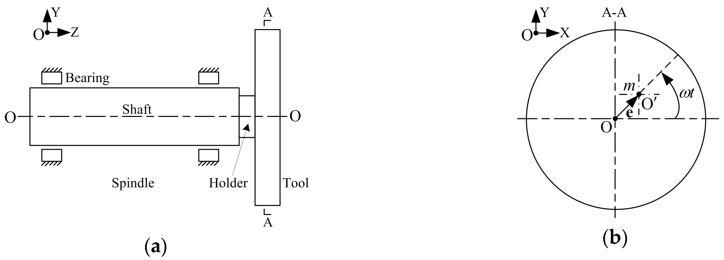
9]. In this paper, the control problem of rotor unbalance for a machine tool motorized spindle is discussed.
Motorized spindle [
10] is a direct drive spindle, which integrates spindle and motor into one element, eliminating the intermediate transmission link; thus, motorized spindles are widely used for high-speed precision cutting machines. However, the high-speed feature also renders motorized spindle more sensitive to rotor unbalance caused by design, machining, assembly, and cutting. Due to tool wear [
11], breakage, change, and so on, mass distribution unbalance of a shaft–holder–tool combined rotor often happens in engineering practice, which firstly causes the spindle to vibrate violently [
12] and then has a severe impact on the workpiece surface quality and spindle service life. It can be seen that there were two main research aspects regarding spindle balancing technology; one involved the balancing method and the other involved a balancing device. The balancing methods mainly include the modal balancing method [
13], the influence coefficient method (ICM) [
14], and magnetic levitation method [
15]. The modal balancing method relies on the accurate dynamics calculation of a rotor, while ICM can avoid complicated calculations and it is easy to carry out on a computer; finally, magnetic bearing cannot directly compensate for the unbalanced mass. The balancing devices mainly include the balancing machine, field balancing instrument, and online balancing system. The on-balancing machine balance [
16] and on-site balance by a portable instrument [
17] are both off-line balancing modes, which need to interrupt the machining process. On-line balancing does not require stopping or human intervention, which allows automatically achieving the precision balancing of spindles. Online balancing systems can be divided into passive [
18] and active balancing systems. Passive balancing is realized by automatic matching of dynamics characteristics of balancer and spindle, which has no controller but requires dynamics design. Active balancing is based on the on-line signal analysis and a balancing algorithm, and the balancer is driven by a controller. The active balancing technology has wider applicability for various rotors compared to passive balancing. Therefore, research on the combined use of ICM and active balancer is currently a hot topic for the on-line balancing of machine tool spindles.
As early as 1964, Vegte [
19] proposed a mechanical automatic balancer that moved within a Cartesian coordinate system. Since then, a variety of polar-coordinate solid counterweight balancers were studied, including the radial steel ball movement-type structure [
20] and electromagnetic ring-type structure [
21]. In addition, some scholars also studied active balancing technology using a liquid counterweight [
22]. For the active balancing method, Gosiewski [
23,
24] initially described the theory and implementation, thereby influencing many subsequent balancing methods. Moon [
25] developed an ICM-based on-line active electromagnetic ring balancing system for high-speed spindles. Dyer [
26] studied an ICM-based single-plane adaptive electromagnetic ring balancing system. Kim [
27] investigated the stability of an ICM-based active electromagnetic ring balancing system. Dyer [
28] implemented an ICM-based robust multiple-plane active electromagnetic ring balancing. Fan [
21,
29,
30,
31,
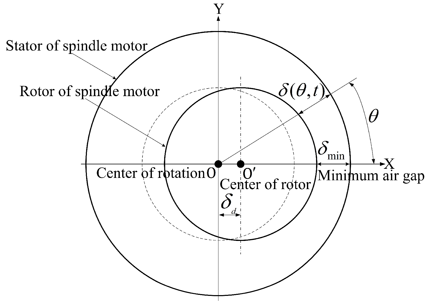
32] revealed the design principle of an electromagnetic ring balancer and the influence of control parameters on the adaptive balancing method, developed an adaptive balancing controller, and experimentally studied the dynamics and thermal performance of a motorized spindle with a single electromagnetic ring balancer. These above researches are the representative achievements of on-line active balancing technology of machine tool spindles. However, they did not consider the unique characteristic of rotor unbalance for a motorized spindle. When a motorized spindle is subject to rotor unbalance, the motor of spindle causes uneven air gap distribution between the stator and rotor, thereby producing an extra undesired magnetic pull. The magnetic pull and magnetic vibration for three-phase asynchronous motors were widely studied [
33,
34], but the air gap eccentricity was never been considered in the active balancing scheme of motorized spindles using a three-phase asynchronous motor, which leads to an inescapable balancing capacity reduction for an online active balancing system.
This paper focuses on a corrected adaptive balancing approach for motorized spindles by eliminating the effect of air gap eccentricity. Firstly, the rotor unbalance of motorized spindle is introduced, and then the air gap unbalance is proposed and the electromagnetic force caused by air gap unbalance is derived. Then, an ICM-based adaptive balancing method for motorized spindles is defined, where the effect of air gap unbalance-induced electromagnetic force on the active balancing is considered. Finally, the balancing tests and vibration analysis of a specific motorized spindle are carried out to prove the effectiveness of the proposed approach.
5. Conclusions
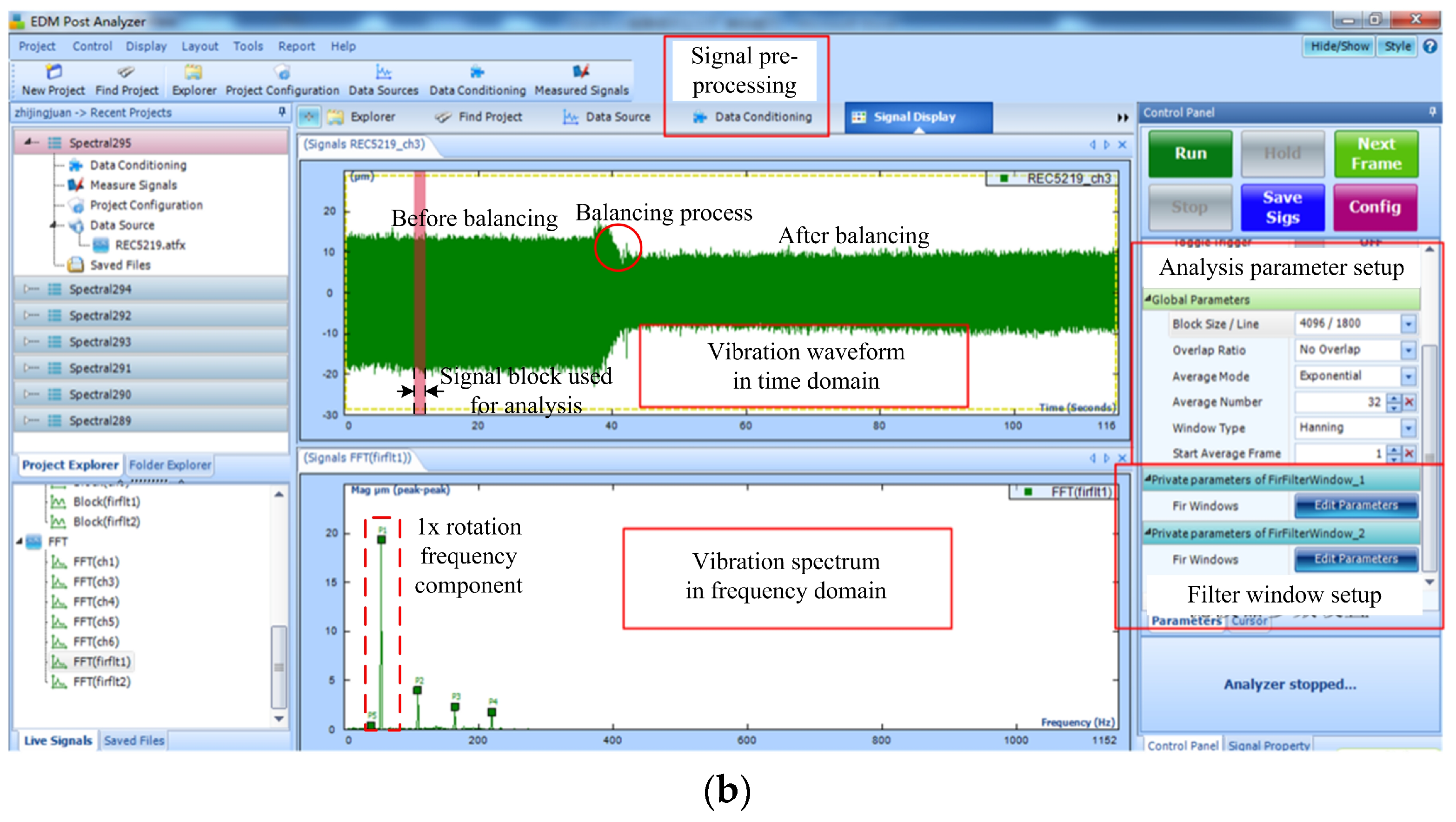
The original intention of this work was to improve the existing rotor adaptive balancing method by considering the effect of air gap unbalance on the balancing scheme, which is an interesting topic for motorized spindles. In order to achieve this goal, we made the following assumptions and simplifications: (i) a single-plane balancing strategy was adopted to mainly reduce the tool unbalance in the machining process, which is an approximation to the tool–holder–shaft combined rotor; (ii) the influence coefficient method (ICM) and the frequency-domain analysis of vibration signals were adopted, which are based on the assumption that the spindle system runs smoothly; however, in practice, the non-stationary factors affect the balancing effect; (iii) in the calculation of unbalanced magnetic pull (UMP), the 1× rotation frequency component with small order and large amplitude was retained, and the correction coefficient was approximately treated. Since the electromagnetic vibration of a motorized spindle is complex, and the rotor balancing cannot be reduced to 0 in practice, the balancing strategy can be accepted as long as its accuracy meets the requirements of the user. Therefore, the above approximations and simplifications are feasible, and the tested results prove this point. This idea is an exploration, and further research will be carried out in the future. The valuable conclusions of this paper are as follows:
(1) The mechanical and electromagnetic effects caused by rotor unbalance for a motorized spindle were introduced. Mechanical unbalance causes an inertia force, while electromagnetic unbalance induces an unbalanced magnetic pull (UMP). The UMP contains many components, whereas this work mainly focused on the 1× rotation frequency component affecting the frequency-domain adaptive balancing strategy. The derivation of UMP for a three-phase asynchronous squirrel-cage spindle motor was given, and, for a specific motorized spindle, the UMP and ratio of the air gap unbalance-induced 1× rotation frequency force component and the total 1× rotation frequency force were determined.
(2) Based on the study on UMP, a newly defined corrected coefficient for the improvement of the active balancing effect was defined. A frequency-domain adaptive balancing algorithm based on the corrected estimation scheme of the influence coefficient was built for motorized spindles.
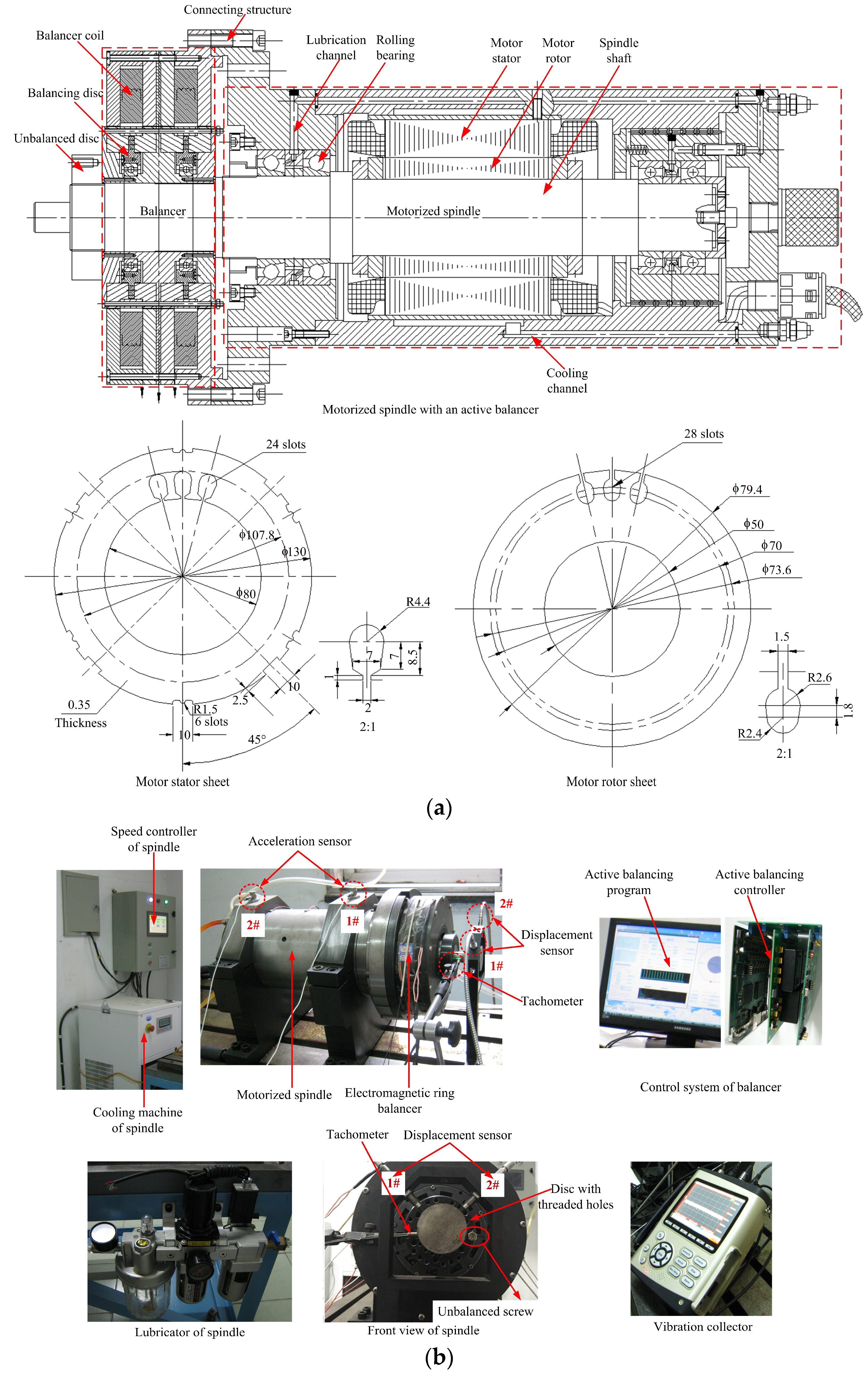
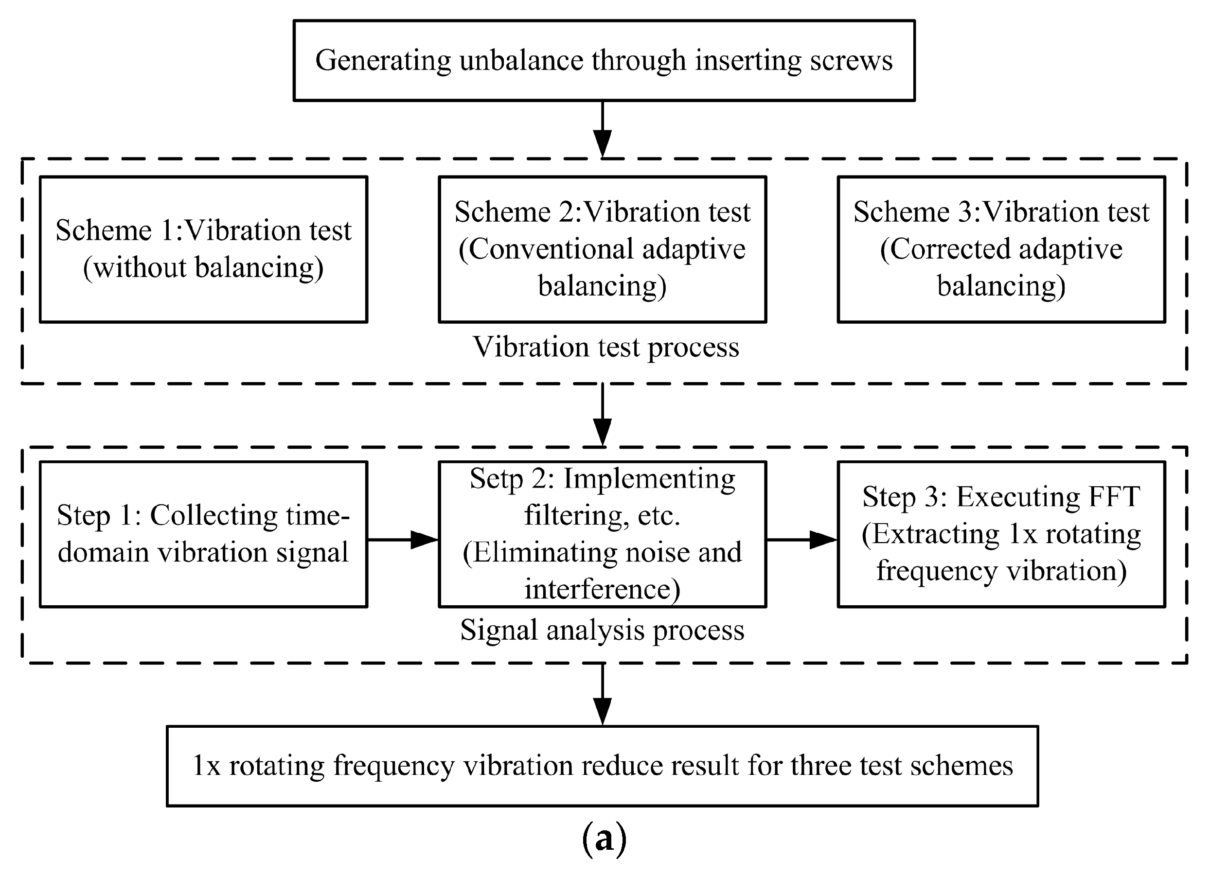
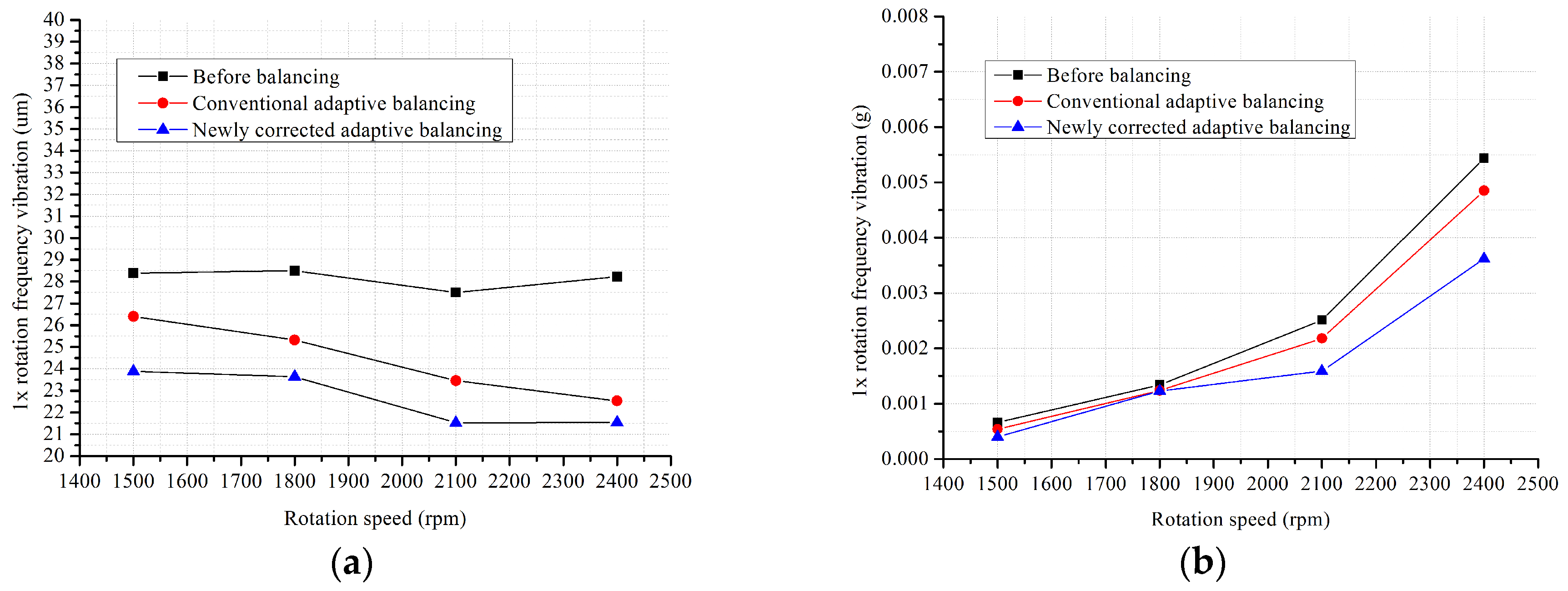
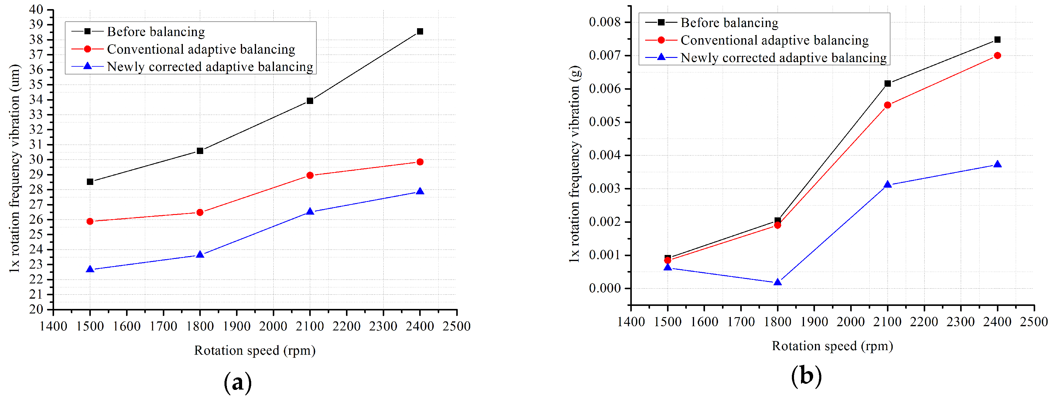
(3) In order to validate the proposed balancing approach, a vibration test bed of a motorized spindle with a single electromagnetic ring balancer was developed. In the tests, two typical unbalance cases were designed, where displacement and acceleration sensors were used and the balancing tests were done at four different speeds. Finally, the balancing data under no balancing, conventional adaptive balancing, and the corrected adaptive balancing schemes were obtained. According to the analysis results, the proposed adaptive balancing approach was surely proven effective for the reduction of residual vibration after balancing for motorized spindles.


