Article

An Investigation into Bolt Anchoring Performance during Tunnel Construction in Bedded Rock Mass

1
School of Civil Engineering, Southwest Jiaotong University, Chengdu 610031, China
2
Key Laboratory of Transportation Tunnel Engineering, Ministry of Education, Southwest Jiaotong University, Chengdu 610031, China
3
State Key Laboratory of Coal Mine Disaster Dynamics and Control, Chongqing University, Chongqing 400044, China
*
Author to whom correspondence should be addressed.
Appl. Sci. 2020, 10(7), 2329; https://doi.org/10.3390/app10072329
Submission received: 18 January 2020 / Revised: 16 March 2020 / Accepted: 22 March 2020 / Published: 28 March 2020
(This article belongs to the Section Environmental Sciences)

Abstract

:
The anchor bolt is a key point of tunnel design in bedded rock mass. The previous theory of anchorage support falls does not fulfil engineering requirements, and the stability of bedded rock must be addressed by empirical methods. To investigate the bolt anchoring performance for bedded rock mass under different anchoring methods, the rock failure mode under shear and tensile stresses in bedded rock was examined in this paper. The results showed that bolt anchoring for rock is achieved mainly through the bonded restoration of surrounding rock near the drill holes by means of an anchoring agent and the supporting resistance provided by the bolt body. It was observed that the strength parameters of bedded rock were increased under the anchoring effect. Full anchoring bolts were especially effective. In addition, it was observed that, in the absence of bolts, the failure form changed from shear to split. In the case of bolting, the failure plane occurred parallel to the bolt’s axis. The shearing began along the interface between the hard and soft rock bedding. Compared to end bolt anchoring, full-length bolt anchoring was more capable of offering an anchoring effect. The latter offered a greater increase in the strength and greater shear-bearing capacity of the rock, which ultimately enabled the rock to bear more load.

1. Introduction

In the past decade, the tunnels and underground projects built in China under complex geological and environmental conditions have made great progress [1,2,3,4,5,6]. Meanwhile, it also faces a series of construction difficulties and challenges [7,8,9,10]. The tunnel composite support system is divided into a primary support and secondary lining (usually concrete lining). The primary support is vital to the tunnel stability and mainly consists of a bolt, sprayed concrete, and reinforcing mesh, and it is supplemented by joist steel or a lattice girder in accordance with the surrounding rock. Moreover, the bolt is the most important support structure of the primary support on account of its high efficiency, economic advantages, and reduced space occupation. Shale forms many bedded and fractured structural planes during the diagenetic process of compaction and cementation, which seriously affects the tunnel stability. The bolt anchoring characteristics for jointed rock mass have been the focus of intense research in China and abroad.
The tunnel bolt is mainly designed for full-length anchoring. During bolting at the construction site, a hole is drilled in the tunnel’s surrounding rock. Then, after grouting or resin application, the body (bolt) is inserted and screwed. In theory, the bolt and surrounding rock mass are bonded in full length via the anchoring agent; however, as the location and angle of the hole differ, bolt construction difficulties vary, especially for the tunnel arch part. Furthermore, it is difficult to ensure the grouting quality of the anchoring agent, which causes the anchorage length of the bolt to vary. Therefore, it is necessary to investigate the impact of anchoring and the stability effect of the jointed rock mass.
The bolt reinforcement effect on jointed rock mass mainly enhances the shear-bearing capacity of the rock mass joint plane. In addition, it prevents the rock mass from developing an intercalated dislocation along the joint plane [11,12]. Many factors affect the reinforcing effect of the bolt on the joint plane, such as the bolt size, hole diameter, pretension force, grouting, and anchored rock mass strength [13,14,15,16,17,18,19,20,21].
Many studies have been conducted on the above aspects. In 1974, Bjurstrom [11] conducted systematic research on the shear property of granite under full-length anchoring and showed that the tangential shear-bearing capacity of the bolt can significantly enhance the stability of the jointed rock mass. Spang et al. [22] and Haas et al. [23] researched the impact of the bolt on the joint shear-bearing capacity of different rocks. Using anchorage tests of jointed rock mass, Yoshinaka et al. [24], Ferrero [25], and Kim et al. [26] analyzed the impact of factors such as the quantity of bolts, elasticity modulus of the bolt body, bolt material, and roughness of the rock joint on the joint shear-bearing capacity. Moreover, Pellet et al. [27] theoretically analyzed the bolt shear-bearing capacity and evaluated the impact of the anchoring angle on the anchoring effect. Grasselli [28] and Jalalifar et al. [29] conducted laboratory shear tests of anchored and jointed rock mass and employed numerical simulation methods to analyze the shear resistance effect of the bolt. They respectively showed that the bolt can form plastic hinges on the joint plane, and that bolt failures mainly occur among the plastic hinges soon thereafter. Meanwhile, Zhang et al. [30] conducted research on the deformation property of a pre-tensioned bolt during a shear test. They determined that the bolt shear-bearing effect occurred after the shear dislocation of the joint plane on account of the bolt “dowelling function”. Teng et al. [31] compared failure modes of end anchoring, full-length anchoring, and non-anchoring by experiment. The result showed that the failure modes of anchored specimens are affected by anchoring type, and they are further divided into shearing extension and shearing offset. Wang et al. [32] simulated the failure mechanism of tunnel segmental lining joints and confirmed that the deformation of the circumferential joints consisted of opening and dislocation, but dislocation was dominant.
In addition, to explore the impact of various factors, Ge et al. [33] carried out shear testing of different bolt sizes, materials, installation angles, specimen strengths, and others. Based on their findings, Chen et al. [34] established a computational formula of structural-plane-anchored specimen shearing strength, which they verified through simulation tests. Furthermore, Liu et al. [35] employed a physical simulation method to assess the impact of the bolt pre-stress force on the shear-bearing capacity of rock mass. Zhang et al. [36] studied the mechanical properties of fractured rock mass under anchoring conditions and uniaxial compression. They further verified the bolt “dowelling function” in terms of the fractured rock mass. Chen et al. [37,38] used a method of anchoring the origin rock specimens and performed respective tensile, uniaxial compression, and pressure–shear tests on rocks. They detailed the rules of crack initiation, extension, and so on of the anchored specimens and verified the relationships between the anchorage and enhancement of the specimen’s mechanical strengths (tensile, compressive, and shear). In addition, they analyzed the anchoring performance. Based on the classical beam theory and the variational principle of minimum complementary energy, Yang et al. [39] analyzed and determined the resisting mechanical behavior of anchor bolts for different rock mass strengths and bolt diameters. Zhang et al. [40] conducted conventional static and dynamic drawing load tests on bonding bolts with end anchorage. The experimental results showed that the distribution of axial stress of a bonded anchor bolt is triangular under static loading. Zhu et al. [41] designed an artificial material and loading system to study the influence of bedding cohesion and anchoring behavior of bedded rock mass. The results showed that the axial stress–strain curve of bedded rock mass under the reinforcement of bolts presents the features of strain softening and secondary strengthening.
As shown above, considerable studies and research results have helped elucidate the jointed rock mass anchoring performance. Obviously, however, many other factors affect the bolt shearing property for jointed rock mass, and the complicated rock strengthening of the jointed rock mass by bolting remains not fully understood. Moreover, the existing theory of anchorage support falls does not fulfil engineering requirements, and designers have to adopt empirical methods to address the stability of rock in most cases. The intention of this paper is to explore the performance of bolts for bedded and jointed rock masses and to figure out the mechanical properties and failure mode of the rock by different anchoring methods.
This study is organized as follows. Section 1 reviews the previous studies made in the field of bolt reinforcement effects. In Section 2 and Section 3, a laboratory test program is designed to analyze the mechanical properties (under uniaxial and shear force) from the viewpoint of mechanical effects and the failure modes of jointed rock with different anchoring methods. Section 4 presents verification of the bolt anchoring effect on a bedded shale tunnel by means of a site test. Finally, Section 5 concludes the current study.

2. Experimental Procedure

C15 specimen material was prepared by mixing cement of river sand and quick lime at a ratio of 1.3:1.5 (river sand to quick lime). It was cured for 28 days at room temperature. The specimens for the uniaxial compression test were prepared with bedding, where mica was selected as the bedding structure. Sheets of mica (100 mesh fineness) were evenly laid between two layers, and the distance between two consecutive layers was 15 mm. The cores were drilled perpendicular to the bedding and were prepared according to the testing standards, i.e., 100 mm in height and 50 mm in diameter. Precast concrete was cut into a cube with a size of 50 mm × 100 mm × 100 mm for the shear test [42].
To bolster the bolt, #45 steel was processed into the screw, and the bolt diameter was 5 mm. The anchoring agent was properly weakened by using chemical grout mixed with ethyl alcohol. The mechanical properties of the screw and bolt are shown in Table 1.
The uniaxial compression test and shear test were both performed on an MTS815.03 Electro-hydraulic Servo-controlled Rock Mechanics Testing System (MTS815) rock mechanical experiment system. Both adopted displacement control for loading at a displacement rate of 0.1 mm/min.

2.1. Uniaxial Compression Testing

According to the size ratios of the bolt and screw, the geometric similarity ratio of the bolt for the uniaxial compression test was determined to be 4:1. With consideration of the specimen’s geometric size, the geometric similarity ratio of its anchoring parameters was designed to be 13.3:1. Three different anchoring schemes were selected: no anchoring, end anchoring, and full-length anchoring. For each kind of anchoring method, three specimens were fabricated to reduce the discreteness. For the anchoring, a torque wrench was used to impose a pre-tightening force of 10 kN. The bedded and anchored specimens are shown in Figure 1.

2.2. Shear Testing

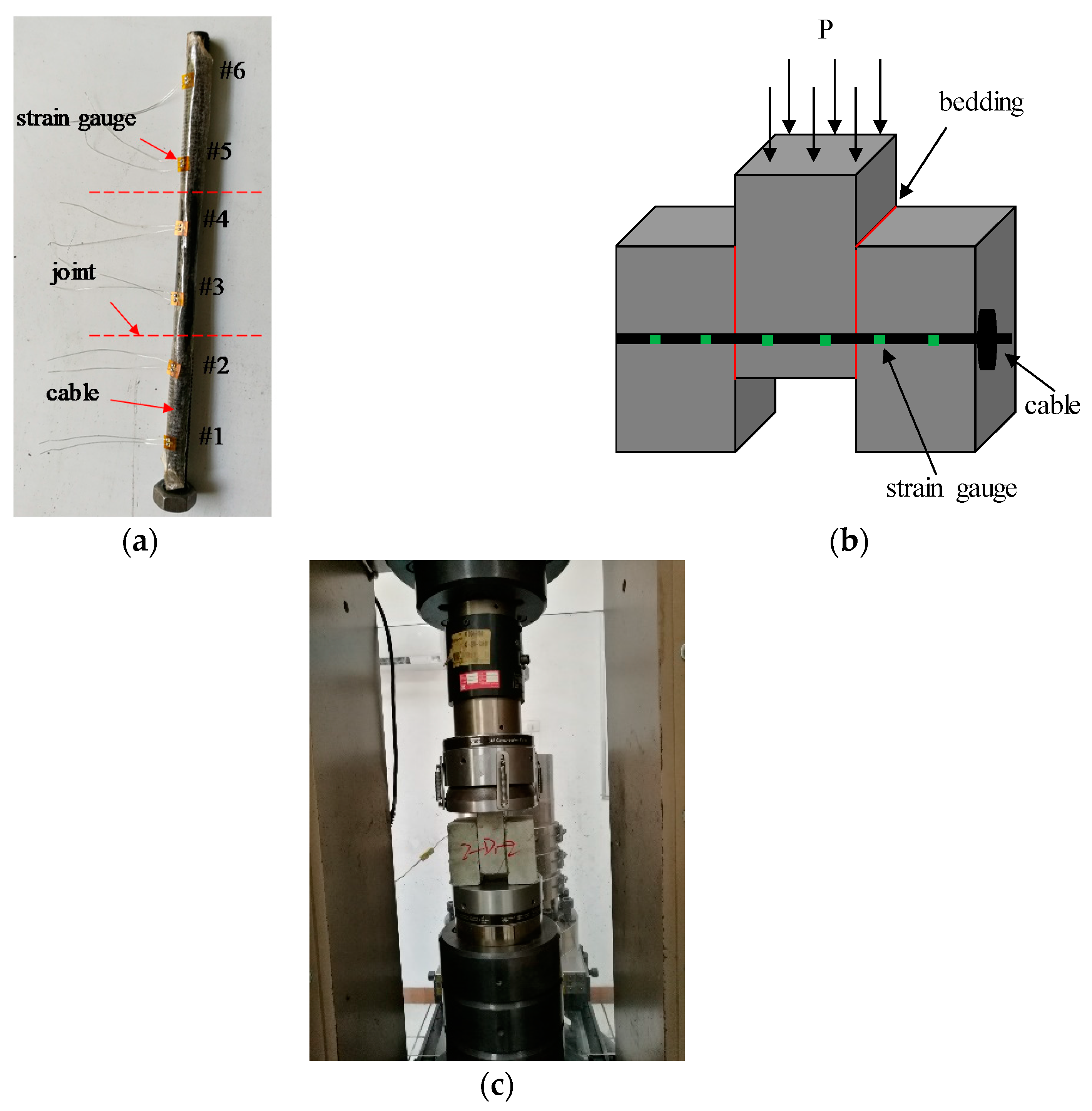
The bolt used for the shear testing was bonded with a highly sensitive strain gauge to measure the axial strain value of the bolt during the test. For each selected scheme (mentioned above), three samples were tested to rule out any error. After the installation, anchored specimens were maintained at normal temperature for seven days, thereby enabling the anchoring agent to completely coagulate. Next, laboratory shear testing was performed. A schematic diagram of the strain gauge arrangement, anchored specimen, and test process is shown in Figure 2.

3. Experimental Results

In the figures of this section, each name in the legend is based on the following convention: test method + anchoring method + number of test group. Uniaxial compression testing and shear testing are represented by “C” and “S”, respectively, for the test method. “N”, “E”, and “FL” denote no anchoring, end anchoring, and full-length anchoring, respectively.

3.1. Uniaxial Compression Testing

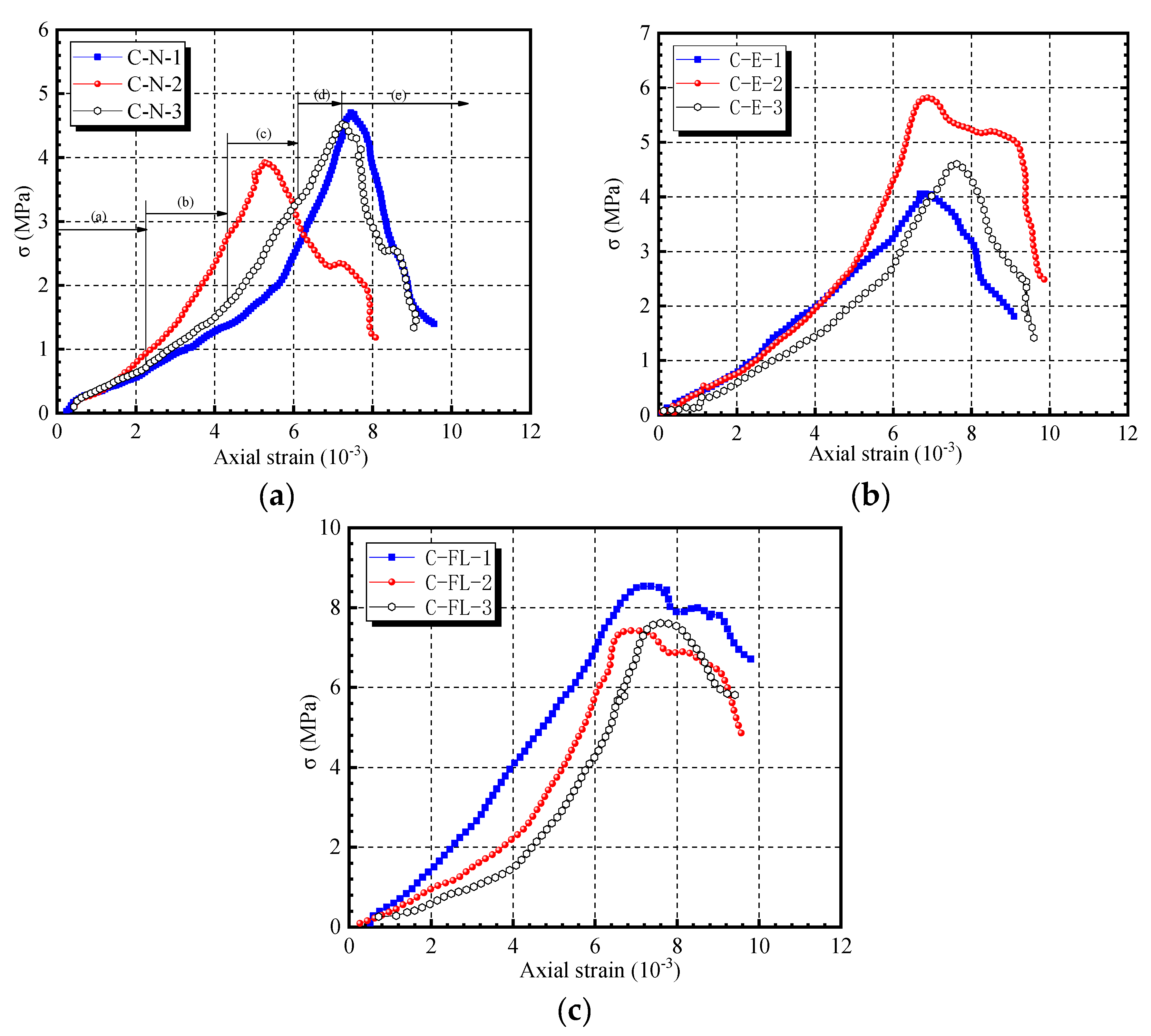
The axial displacement was directly measured using an MTS815 rock mechanical experiment system; curves of the specimens’ axial strain for the earlier mentioned anchoring methods (no anchoring, end anchoring, and full-length anchoring) are shown in Figure 3.
A close examination of the figure reveals the following key observations.
Five phases of the stress–strain curve in every case are obvious. Taking curve C-N-3 in Figure 3a as an example, we see the (a) initial compression phase, (b) elastic deformation phase,(c) phase of microfracture, (c) stable development phase, (d) phase of unstable fracture and development, and (e) post-fracture phase. In the first phase, the initial compression phase, the duration of the end anchoring specimen is longer than that with no anchoring; moreover, it is shortest for the full-length anchoring specimen. The cause of this is analyzed below.
The initial rock compression closure mainly refers to the closure of the rock’s internal structural plane and primary microfracture by compression. It is assumed that the secondary cracks produced during sample preparation (drilling, grouting, etc.) may have an adverse effect on the bolt because the anchoring range of the end anchoring bolt is relatively small. Its anchoring end is tightly bonded with the rock. Some space exists between the bolt body of the non-anchor segment and the rock.
In the full-length anchoring specimen, the anchoring bolt is tightly bonded with the rock by the anchoring agent. Moreover, the anchoring agent has the effect of bonded amalgam restoration on specimen damage. It forms a reinforcing area within a certain range around the bolt body. Therefore, at the implementation of the uniaxial compression test, for the case of no anchoring or horizontal bedding specimens, the first phase is mainly the closure of the bedding plane. For the end anchoring specimens, it is not only bedding plane closure, but also the compression process of the space between the bolt and rock. For the full-length anchoring specimens, it is mainly the compression of bedding in the non-anchor area.
After the bearing capacity of the no-anchoring specimen has reached the strength peak, the specimen fails rapidly, and the section of the stress–strain curve after the peak is relatively steep. When the bearing capacity of the anchored specimen has reached the strength peak, the load and resulting plastic deformation of the specimen continue to increase. Thus, this section can be referred to as the “plasticity strengthening section”.
After the anchoring of specimens, both the average uniaxial compressive strength and elasticity modulus are increased [42]. As the anchoring methods are different, the increased range of the anchored specimen differs. In comparison with the no-anchoring specimens, as shown in Figure 4, the uniaxial compressive strength of the end anchoring specimen is increased by 12.73%, while the uniaxial compressive strength of the full-length anchoring specimen is increased by 62.71%. Similarly, the elasticity modulus of the end anchoring specimen is increased by 6.31%, while the elasticity modulus of the full-length anchoring specimen is increased by 58.73%.
The failure patterns of specimens under different anchoring modes are shown in Figure 5.
When there is no anchor, the failure mode of the specimen is mainly shear failure along the bedding and axial splitting failure perpendicular to the bedding. For end anchoring, the bonding force of the anchoring agent at the end of the bolt limits the surrounding rock’s shear failure along the bedding, and the "pin effect" of bolts makes it difficult for the specimen to split along the axial direction. The specimen finally shows axial shear tensile failure, as shown in Figure 6a.
Under full-length anchorage, shear failure occurs along the middle or end of the specimen. The reason for this is that under the action of full-length bonding and bolt “pin action”, the strength of the specimen near the two ends of the bolt is increased, and the interior is relatively soft, so there is a “soft–hard interface” in the specimen. Shear failure occurs along the “soft–hard interface” under load, as shown in Figure 6b.
On the basis of this, the reinforcement mechanism of the bolt can be summarized as follows.
(1) The anchoring agent has a bonding effect and damage repairing effect on rock mass around boreholes. Joints, fissures, and other structural planes often exist in the rock forming process, which reduce the mechanical properties of rock, large-scale structural planes, and even the controlling factors of surrounding rock failure. The anchoring agent enters the structural plane under grouting pressure and plays a role in bonding and strengthening the surrounding rock near the structural plane, thus forming a “reinforcement area” within a certain range. The size of the “reinforcement area” is related to the grouting pressure, the material properties of the anchoring agent, the pore distribution of the surrounding rock, and so on.
(2) The axial tensile and tangential shear capacity of the bolts can improve the stress state of the specimen. Under load, the specimen is affected by both the shear action along the bedding plane and the tension action along the axis (Figure 5a). When the specimen is deformed, the tension and shear action are applied to the bolt, and the bolt body provides support resistance, which limits the deformation of the specimen.
Based on the above findings, we inferred that the anchoring increases the specimen strength and changes the failure plane direction by improving the tensile capacity and tangential shear-bearing capacity. Under axial compression, the specimen simultaneously bears the shear effect along the bedding and the tensile effect along the axial direction (as shown by Figure 5a), while the bolt body provides support resistance to restrain the specimen deformation.
Based on the analysis of the bolt reinforcing performance, we determined that a difference existed between the reinforcing effect of the bolt for full-length anchoring and that for end anchoring. The gap between the bolt body for full-length anchoring and the surrounding rock was filled by the anchoring agent, which could bond and reinforce the surrounding rock with greater scope. In the case of the rock developing shear deformation, the bolt with full-length anchoring could immediately restrain further deformation. Meanwhile, a gap existed between the end anchoring bolt and surrounding rock. The bolt’s tangential anchoring force only played a role when the surrounding rock developed a certain tangential deformation. Therefore, the bolt for full-length anchoring could form an “anchoring area” of greater range and provide greater support resistance than the end anchoring bolt.

3.2. Shear Testing

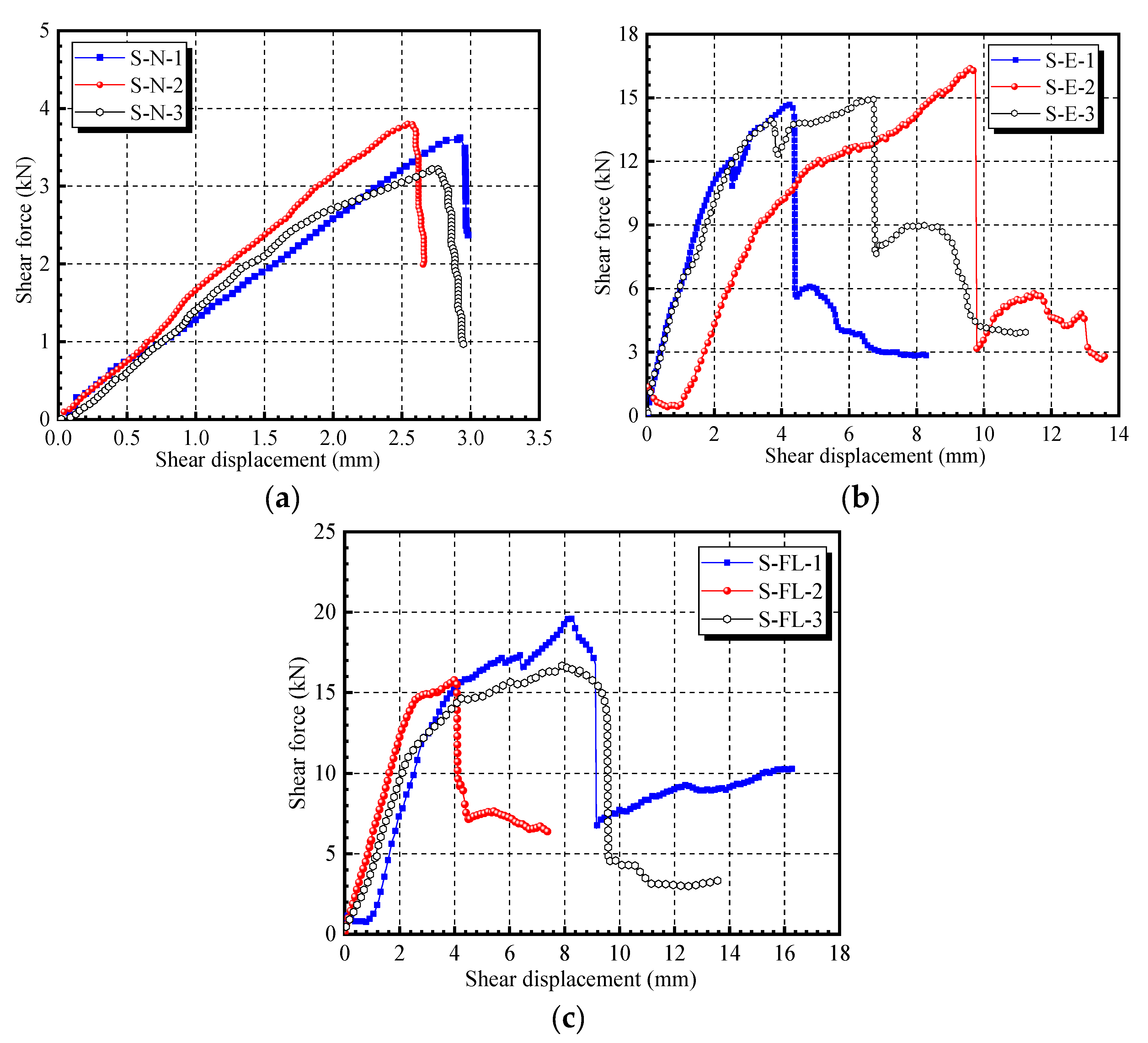
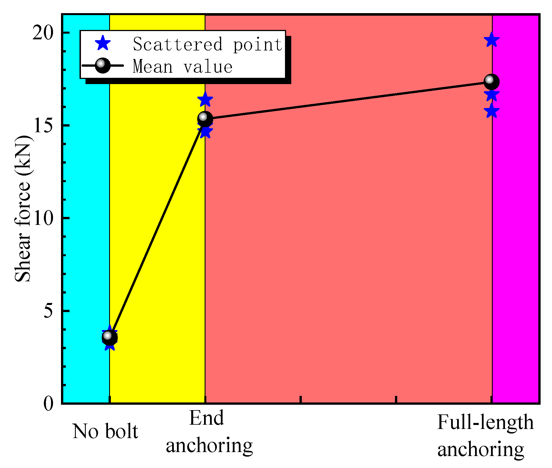
The shear–displacement curves of different anchoring methods, which were measured by strain gages, are shown in Figure 7. The average maximum shear force values of the no-anchoring specimen, end anchoring specimen, and full-length anchoring specimen were, respectively, 3.55 kN, 15.34 kN, and 17.35 kN, as shown in Figure 8. It is evident that the maximum shear force of the end anchoring specimen was increased by 332.11% while the maximum shear force of the full-length anchoring specimen was increased by 13.10% compared with that of the end anchoring specimen. The shear–displacement curve of the no-anchoring specimen mainly shows the shear deformation process of the joint plane.
Figure 7a shows that the specimen develops buckling failures as it is loaded to its ultimate load, resulting in a loss in the bearing capacity and representing a brittle feature. Moreover, the end anchoring specimen develops a “turning point” of a sudden drop and then a rise in shear force prior to its full yield to failure, as shown by Figure 7b. This occurrence was not observed in the other two cases. This point can be regarded as the decision point in terms of whether the bolt of the end anchoring specimen engages its shear resistant effect.
Before this point, the joint plane mainly bears the shear effect. The extent of its shear stiffness mainly depends on the friction force of the plane and the pre-stressing force of the bolt. At failure, the joint plane suffered shear failures, and the specimen at both sides developed relative sliding, thus mobilizing the shear strength of the bolt itself. Therefore, this point can also be referred to as the “yield point” of the joint plane and the “mobilization point” of the bolt’s shear strength. After this point, the shear strength of the bolt body enhanced the comprehensive shear-bearing performance of the joint plane. Meanwhile, the shear force increased slowly with increasing shear displacement. These are called the plastic phase and plastic strength phase [34,43]. Others refer to them as the slowly increasing resistance phase [24].
In accordance with the characteristics of the bolt resistance increase, the bolt developed plastic hinges at both sides of the joint plane. When the strength of the bolt or concrete reached its limit strength, the anchored specimen developed buckling failures. It was also observed that the patterns of the full-length anchoring specimen and end anchoring specimen’s shear–displacement curves varied somewhat (Figure 7c). The bolt of the full-length anchoring specimen was in tight contact with the concrete via the anchoring agent. It could resist the shear resistance effect immediately under the load effect until the specimen developed buckling failures. The bolt of the full-length anchoring specimen and its joint plane jointly bore the shear load. No “turning point” developed. The same occurrence was observed in the end anchoring case. Compared to the no-anchoring specimen, the end anchoring specimen and full-length anchoring specimen represented a larger ultimate load, a more rapid and greater increase of bolt resistance, a longer plastic strength phase, and a stronger residual shear-bearing capacity after buckling.
The typical strain distribution curves of the end anchoring specimen and full-length anchoring specimen segments obtained by the test are shown in Figure 9. The following can be observed from the strain distribution curves.
  • The maximum value of the bolt axial force is near the joint plane and is anti-symmetrically distributed at both sides of the joint plane.
  • The axial force of the bolt for full-length anchoring is mainly concentrated near the joint plane. It decreases rapidly with increasing distance from the joint plane, and its distribution is relatively uniform.
  • Plastic hinges are produced near the joint plane, which can effectively stop the further spread of the stress force. One end of the plastic hinge bears the tensile stress, while the other end bears the pressure stress.

4. Field Application

4.1. Project Description

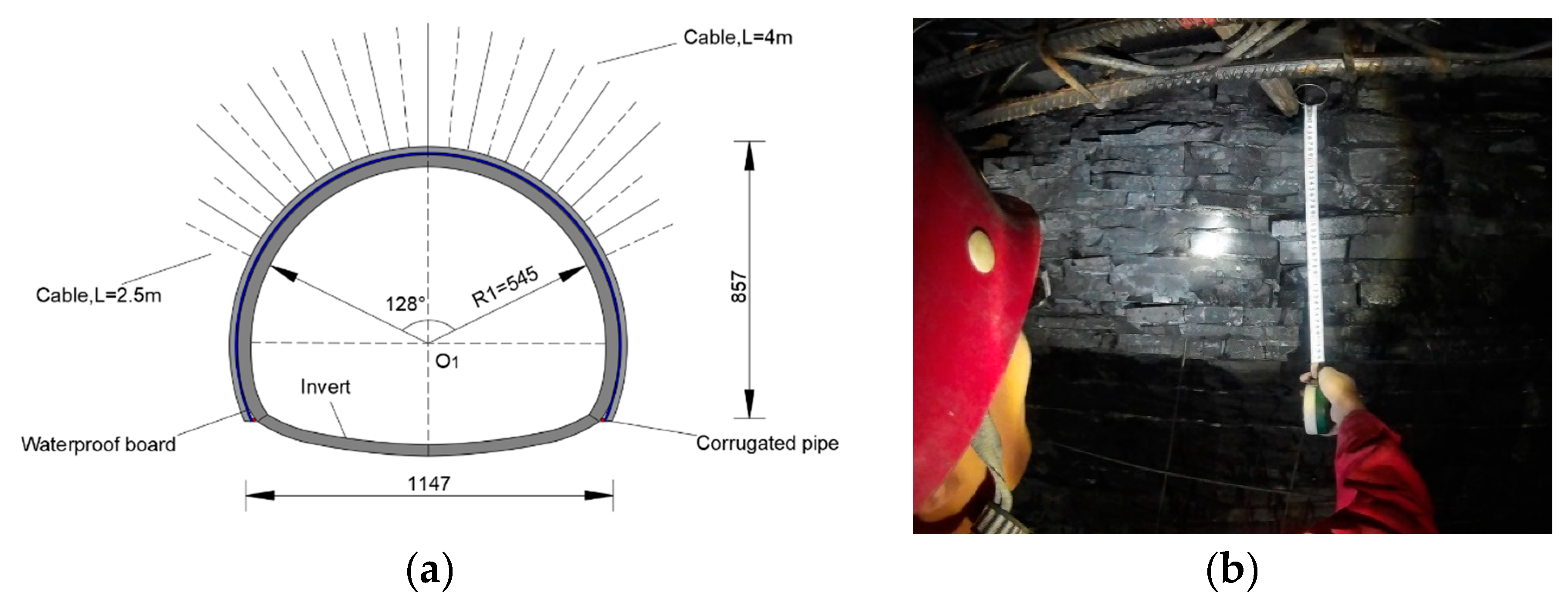
The test field was the Mazhui Tunnel of DaoZhen Highway from Nanchuan of Chongqing to Guizhou, China. It was designed to be a bidirectional four-lane highway, with a full length of 3711 m and a maximum burial depth of 441 m. The lithological character of the test section is Silurian Longmaxi Formation shale with thin bedding, fracture development, and abundant underground water. The tunnel has a composite lining and is primary supported by bolts, sprayed concrete, and reinforcing mesh. The parametric description is C20 sprayed concrete of a thickness of 18 cm, Φ22 cartridge bolts with inter-row spacing of 100 × 120 cm and 2.5 m in length, and 18# joist steel with longitudinal spacing of 1 m. The secondary lining was molded concrete with a thickness of 40 cm of C25 sprayed concrete. The support parameters of the tunnel section and geological conditions of the testing face surrounding rock are shown in Figure 10.

4.2. Bolt Arrangement at the Construction Site

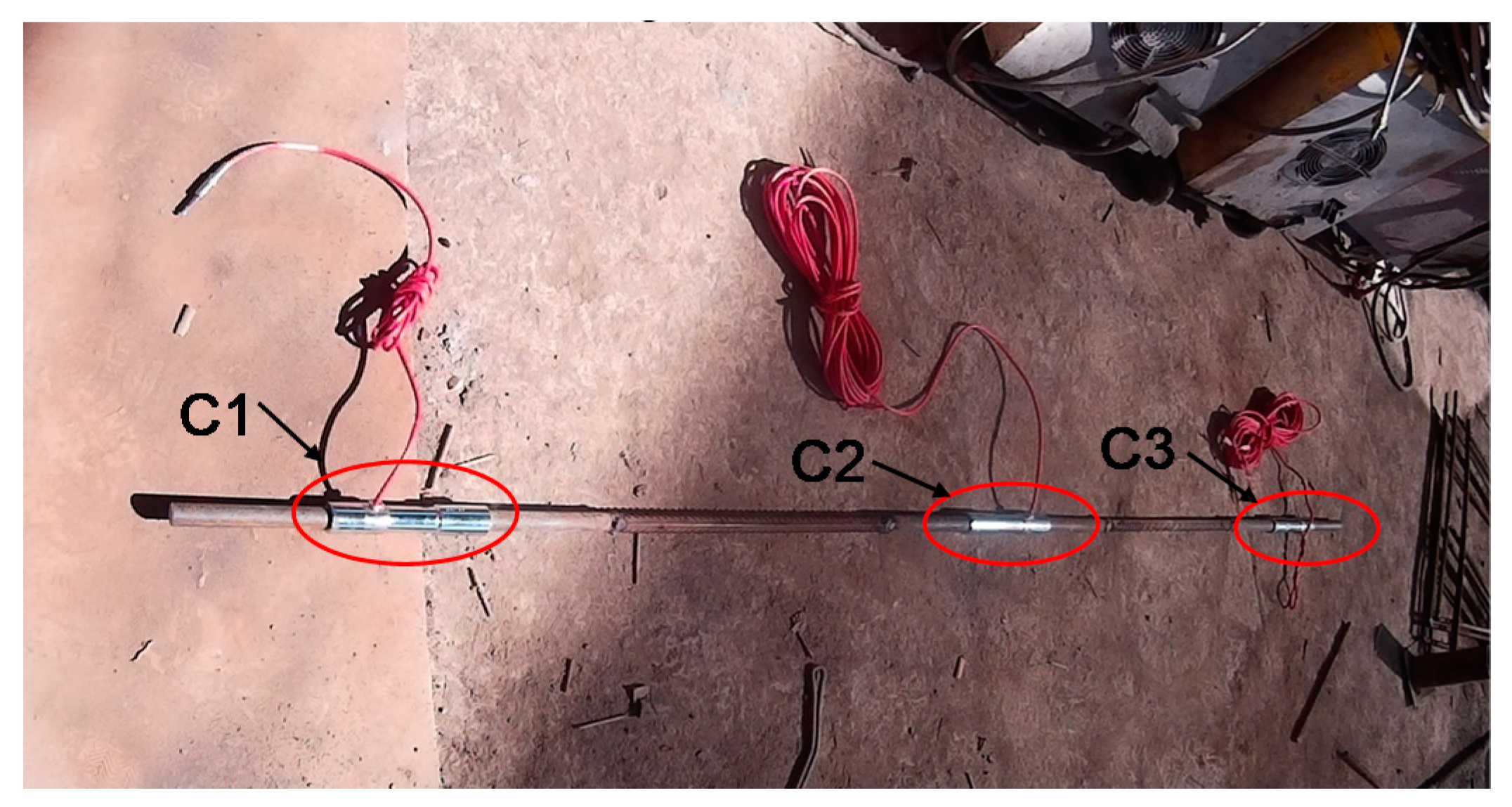
Bolts with lengths of 3.5 m with diameters of 22 mm were used in the field. The measuring bolts and vibration wire steel stress gauges were installed to measure the axial force of the bolts, as shown in Figure 11. Each measuring bolt was installed with three vibrating wire steel stress gauges with corresponding measuring lines. At the measuring station, the plug of each measuring line was inserted into the frequency recorder to record the value. Each vibrating wire steel stress gauge was calibrated indoors to obtain its reference frequency and calibration coefficient prior to its installation and use. The frequencies obtained from the field test were computed on the basis of a calibration formula to obtain the axial force of the bolt segments.
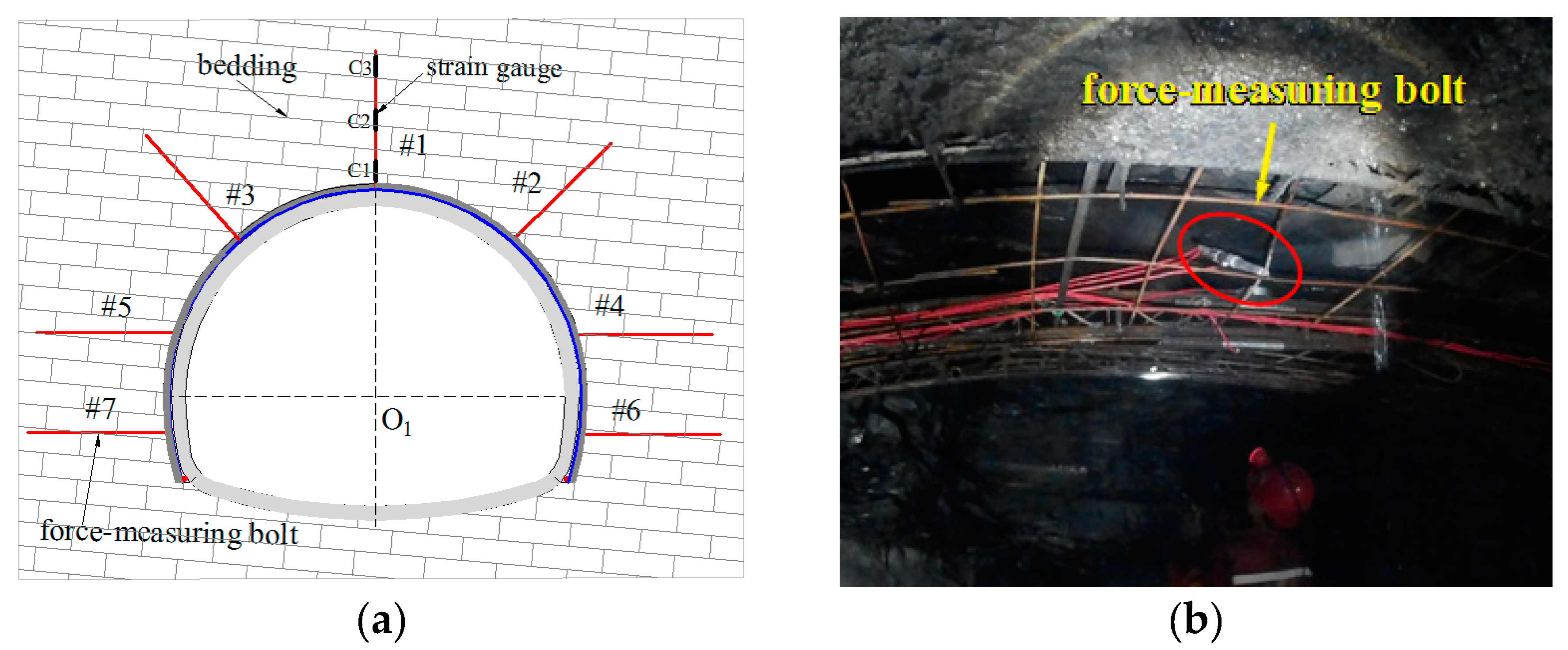
Two site sections in the field ZK17+360 to ZK17+365 (“ZK17” means the 17th kilometer of left line of DaoZhen Highway, “360” and “365” mean detailed distance(meters) in ZK17.) were selected to test the bolt axial force variations. These sites were the tunnel evacuation face and secondary lining, respectively. In each section, seven bolts were installed. To compare the impact of the anchoring methods on the anchorage effect, the ZK17+360 section adopted full-length anchoring, while the ZK17+365 section adopted the end anchoring scheme. The distribution method of the measuring bolts and site construction are shown in Figure 12. The test field simultaneously measured the periphery convergence and arch crown settlement of the two sections to analyze the support effect of the bolt. The periphery convergence was measured by a JSS30A convergence gauge, while the arch crown settlement was measured by a DSZ2 automatic compensated level.
The ultimate axial force distribution of the measuring bolts at each section is shown in Figure 13. The positive sign represents compressive force; the negative sign represents tensile force. The figure shows that, at section ZK17+360, all bolts mainly bear tensile stress. As a whole, the stress borne by bolts in the ZK17+360 section is greater than that borne by bolts in the ZK17+365 section. That is, under full-length anchoring, the bolts can provide greater support resistance and hence obtain a better anchorage effect. The axial forces of bolts in different parts of the test section also have certain regularities, as outlined below.
The #2 bolt on the right arch shoulder bears the maximum stress., while the maximum tensile stresses are distributed near the middle of the bolt. These are 55.2 kN (C2 element for full-length anchoring) and 27.7 kN (C2 element for end anchoring). This is consistent with the deformation distribution of the tunnel’s surrounding rock, as shown in Figure 14. Moreover, the maximum deformation point of the tunnel arch crown is located at the right spandrel. At the construction site, this location frequently developed cracking and chipping, and it even extruded and deformed the lattice girder.
The axial force of the bolt on the wall at each side of the test section was relatively small (5 to 10 kN), especially on bolts #6 and #7 on the wall at each side. These were installed after the evacuation of the lower bench, while the deformation of the tunnel’s surrounding rock tended to be stable after evacuation of the lower bench. Bolts in this part did not engage their anchoring effects; rather, they became a kind of safety stock.

5. Discussion

In laboratory experiments, the specimen needs to be drilled when installing the bolt. In the process of drilling, the drill stem may disturb the specimen and cause damage to the rock around the drill hole. Although the rock morphology near the borehole is examined in the test process (to check that there are no macroscopic damage fractures), the degree of damage to the specimen when drilling and its influence on the test are open to question. In engineering, carrying out on-site bolt construction will also cause damage to the surrounding rock in a certain area near the borehole. How to quantitatively evaluate and compare the relationship between indoor testing and on-site construction is worthy of further research and discussion.

6. Conclusions

In this paper, we investigated the bolt anchoring performance for bedded rock mass under different anchoring methods, as well as the failure mode under shear and tensile stresses in bedded rock. Then, based on field tests, we analyzed the force and support effects of the different anchoring methods. The conclusions are as follows:
(1)
With respect to the anchored specimen strength and strain, the reinforcing mechanism of the bolt for the rock was divided into two aspects: the anchoring agent bonding and restoring the surrounding rock near the reinforcing zone, and the bolt body resistance supporting and improving the stress state of the rock. The combined action of those two aspects increased the strength parameters of the anchored specimen.
(2)
Failure of the anchored specimen changed from shear splitting failure with no anchoring into shear failure where the failure plane slid parallel to the axial direction of the bolt or shear dislocation failure along the soft–hard interface.
(3)
Via anchoring of the joint rock mass, the bolt could significantly enhance the shear-bearing capacity of the rock mass and increase the stability of the surrounding rock. Compared to the end anchoring bolt, the bolt for full-length anchoring can form an “anchoring area” of a greater range and provide greater support resistance than the end anchoring bolt; therefore, it had a better coupling effect on the surrounding rock with a greater resistance increase. This occurrence enabled the surrounding rock to bear more load.
(4)
Full-length anchoring can provide more support resistance and have a better anchoring effect on the surrounding rock of a bedded rock tunnel. However, the grouting quality is often difficult to guarantee due to the impact of the bolt insertion angle, so it is necessary to pay attention to the filling quality of the anchoring agent, especially at the vault of the tunnel.

Author Contributions

Z.Z. analyzed the calculation results. Y.L. carried out the laboratory test and wrote the article. J.T. provided the information of the construction site. H.Z. offered useful suggestions for the preparation and writing of the paper. X.C. processed the data. All authors have read and agreed to the published version of the manuscript.

Funding

The authors are very grateful for the funding from the High Speed Railway and Natural Science United Foundation (U1934213) and the General Program of National Natural Science Foundation of China (51878572).

Acknowledgments

We also highly appreciate the reviewers for their useful comments and editors for improving the manuscript.

Conflicts of Interest

The authors declare no conflict of interest.

References

  1. Zhang, H.; Chen, L.; Zhu, Y.; Zhou, Z.; Chen, S. Stress field distribution and deformation law of large deformation tunnel excavation in soft rock mass. Appl. Sci. 2019, 9, 865. [Google Scholar] [CrossRef] [Green Version]
  2. Zhu, Y.; Chen, L.; Zhang, H.; Zhou, Z.; Chen, S. Physical and mechanical characteristics of soft rock tunnel and the effect of excavation on supporting structure. Appl. Sci. 2019, 9, 1517. [Google Scholar] [CrossRef] [Green Version]
  3. Zhang, Z.Q.; Zhang, H.; Tan, Y.J.; Yang, H.Y. Natural wind utilization in the vertical shaft of a super—Long highway tunnel and its energy saving effect. Build. Environ. 2018, 145, 140–152. [Google Scholar] [CrossRef]
  4. Zhang, Z.; Luo, C.; Zhang, H.; Gong, R. Rockburst identification method based on energy storage limit of surrounding rock. Energies 2020, 13, 343. [Google Scholar] [CrossRef] [Green Version]
  5. Zhang, H.; Chen, L.; Chen, S.G.; Sun, J.C.; Yang, J.S. The spatiotemporal distribution law of microseismic events and rockburst characteristics of the deeply buried tunnel group. Energies 2018, 11, 3257. [Google Scholar] [CrossRef] [Green Version]
  6. Li, P.L.; Lu, Y.Q.; Lai, J.X.; Liu, H.Q. A comparative study of protective schemes for shield tunneling adjacent to pile groups. Adv. Civ. Eng. 2020, 2020, 1874137. [Google Scholar] [CrossRef] [Green Version]
  7. Zhang, H.; Zhu, Y.; Chen, L.; Hu, W.; Chen, S. The prevention and control mechanism of rockburst hazards and its application in the construction of a deeply buried tunnel. Appl. Sci. 2019, 9, 3629. [Google Scholar] [CrossRef] [Green Version]
  8. Zhang, Z.Q.; Li, H.Y.; Yang, H.Y.; Wang, B. Failure modes and face instability of shallow tunnels under soft grounds. Int. J. Damage Mech. 2019, 28, 566–589. [Google Scholar] [CrossRef]
  9. Liu, T.; Zhong, Y.J.; Feng, Z.H.; Xu, W.; Song, F.T. New construction technology of a shallow tunnel in boulder-cobble mixed grounds. Adv. Civ. Eng. 2020, 2020, 5686042. [Google Scholar] [CrossRef] [Green Version]
  10. Zhang, Z.Q.; Shi, X.Q.; Wang, B.; Li, H.Y. Stability of NATM tunnel faces in soft surrounding rocks. Comput. Geotechnol. 2018, 96, 90–102. [Google Scholar] [CrossRef]
  11. Bjurstrom, S. Shear strength of hard rock joints reinforced by grouted untensioned bolts. Proc. 3rd Cong. ISRM Denver 1974, 2, 1194–1199. [Google Scholar]
  12. Cai, Y.; Esaki, T.; Jiang, Y. An analytical model to predict axial load in grouted rock bolt for soft rock tunnelling. Tunn. Undergr. Space Technol. 2004, 19, 607–618. [Google Scholar] [CrossRef]
  13. Cai, Y.; Jiang, Y.; Djamaluddin, I.; Iura, T.; Esaki, T. An analytical model considering interaction behavior of grouted rock bolts for convergence–confinement method in tunneling design. Int. J. Rock Mech. Min. Sci. 2015, 76, 112–126. [Google Scholar] [CrossRef]
  14. Carranza-Torres, C. Analytical and numerical study of the mechanics of rockbolt reinforcement around tunnels in rock masses. Rock Mech. Rock Eng. 2009, 42, 175–228. [Google Scholar] [CrossRef]
  15. Farmer, I. Stress distribution along a resin grouted rock anchor. Proc. Int. J. Rock Mech. Min. Sci. Geomech. Abstr. 1975, 12, 347–351. [Google Scholar] [CrossRef]
  16. Freeman, T. The behaviour of fully-bonded rock bolts in the Kielder experimental tunnel. Tunn. Tunn. Int. 1978, 10, 37–40. [Google Scholar]
  17. Liu, Q.; Lei, G.; Peng, X. Advance and review on the anchoring mechanism in deep fractured rock mass. Chin. J. Rock Mech. Eng. 2016, 35, 312–332. [Google Scholar]
  18. Ma, S.; Nemcik, J.; Aziz, N. An analytical model of fully grouted rock bolts subjected to tensile load. Constr. Build. Mater. 2013, 49, 519–526. [Google Scholar] [CrossRef]
  19. Windsor, C. Rock reinforcement systems. Int. J. Rock Mech. Min. Sci. 1997, 34, 919–951. [Google Scholar] [CrossRef]
  20. Yang, S.; Li, H.; Zhu, H. Reinforcement of bolt in joints. Rock Soil Mech.-Wuhan- 2002, 23, 604–607. [Google Scholar]
  21. Zhang, B.; Li, S.; Xia, K.; Yang, X.; Zhang, D.; Wang, S.; Zhu, J. Reinforcement of rock mass with cross-flaws using rock bolt. Tunn. Undergr. Space Technol. 2016, 51, 346–353. [Google Scholar] [CrossRef]
  22. Spang, K.; Egger, P. Action of fully-grouted bolts in jointed rock and factors of influence. Rock Mech. Rock Eng. 1990, 23, 201–229. [Google Scholar] [CrossRef]
  23. Haas, C.J. Shear resistance of rock bolts. Trans. Soc. Min. Eng. AIME 1976, 260, 32–40. [Google Scholar]
  24. Yoshinaka, R.; Sakaguchi, S.; Shimizu, T.; Arai, H.; Kato, E. Experimental study on the rock bolt reinforcement in discontinuous rocks. In Proceedings of the 6th ISRM Congress, Montreal, QC, Canada, 30 August–3 September 1987. [Google Scholar]
  25. Ferrero, A.M. The shear strength of reinforced rock joints. Proc. Int. J. Rock Mech. Min. Sci. Geomech. Abstr. 1995, 32, 595–605. [Google Scholar] [CrossRef]
  26. Kim, H.-J.; Hu, J.-W.; Hwang, W.-S. Cyclic testing for structural detail improvement of CFT column-foundation connections. Sustainability 2015, 7, 5260–5281. [Google Scholar] [CrossRef] [Green Version]
  27. Pellet, F.; Egger, P. Analytical model for the mechanical behaviour of bolted rock joints subjected to shearing. Rock Mech. Rock Eng. 1996, 29, 73–97. [Google Scholar] [CrossRef]
  28. Grasselli, G. 3D behaviour of bolted rock joints: Experimental and numerical study. Int. J. Rock Mech. Min. Sci. 2005, 42, 13–24. [Google Scholar] [CrossRef]
  29. Jalalifar, H.; Aziz, N. Experimental and 3D numerical simulation of reinforced shear joints. Rock Mech. Rock Eng. 2010, 43, 95–103. [Google Scholar] [CrossRef]
  30. Zhang, W.; Liu, Q. Analysis of deformation characteristics of prestressed anchor bolt based on shear test. Rock Soil Mech. 2014, 35, 2231–2240. [Google Scholar]
  31. Teng, J.Y.; Zhang, Y.N.; Tang, J.X.; Zhang, C.; Li, C.L. Mechanical behaviors of anchored bedding rock under uniaxial compression. Rock Soil Mech. 2017, 38, 1974–1982+1998. [Google Scholar] [CrossRef]
  32. Wang, Z.; Wang, L.; Li, L.; Wang, J. Failure mechanism of tunnel lining joints and bolts with uneven longitudinal ground settlement. Tunn. Undergr. Space Technol. 2014, 40, 300–308. [Google Scholar] [CrossRef]
  33. Ge, X.; Liu, J. Study on the shear Resistance Behaviour of Bolted Rock Joints. Chin. J. Geotech. Eng. 1988, 1, 8–19. [Google Scholar]
  34. Chen, W.; Jia, Z.; Zhao, Y.; Liu, L.; Zhou, J.; Lin, X. Analysis of axial and transverse effects of rock bolt during shearing process. Rock Soil Mech. 2015, 36, 143–148. [Google Scholar]
  35. Liu, A.; Ju, W.; Hu, H.; Wang, X. Experimental study on the effect of bolt prestress on the-shear behavior of jionted rockmass. J. China Coal Soc. 2013, 38, 391–396. [Google Scholar]
  36. Zhang, B.; Shucai, L.; Xueying, Y. Bolting effect and failure modes of jointed rock masses with cross-cracks. Chin. J. Rock Mech. Eng. 2014, 33, 996–1003. [Google Scholar]
  37. Chen, L.; Zhang, C.; Yu, F. Experimental study of flexural behavior of anchored rock. Rock Soil Mech. 2014, 35, 3451–3459. [Google Scholar]
  38. Chen, L.; Tan, Y.; Zang, C. Test study of mechanical properties and failure characteristics of anchored rock. Rock Soil Mech. 2014, 35, 413–422. [Google Scholar]
  39. Yang, B.; Xiao, M.; Luo, N.; Wang, X. Research on mechanical characteristic of anchor bolt in process of shearing. J. Huazhong Univ. Sci. Technol. Nat. Sci. 2019, 47, 127–132. [Google Scholar]
  40. Zhang, X.; Wang, S.; Zhao, Y.; Sun, X. Non-uniform stress anchor element based on static and dynamic loading tests on bonded anchor bolt of end anchorage. Rock Soil Mech. 2016, 37, 269–278. [Google Scholar]
  41. Zhu, W.X.; Jing, H.W.; Yang, L.J.; Pan, B.; Su, H.J. Strength and deformation behaviors of bedded rock mass under bolt reinforcement. Int. J. Min. Sci. Technol. 2018, 28, 593–599. [Google Scholar] [CrossRef]
  42. Ulusay, R. The ISRM Suggested Methods for Rock Characterization, Testing and Monitoring: 2007–2014; Springer: Berlin, Germany, 2014. [Google Scholar]
  43. Li, C.; Stillborg, B. Analytical models for rock bolts. Int. J. Rock Mech. Mining Sci. 1999, 36, 1013–1029. [Google Scholar] [CrossRef]
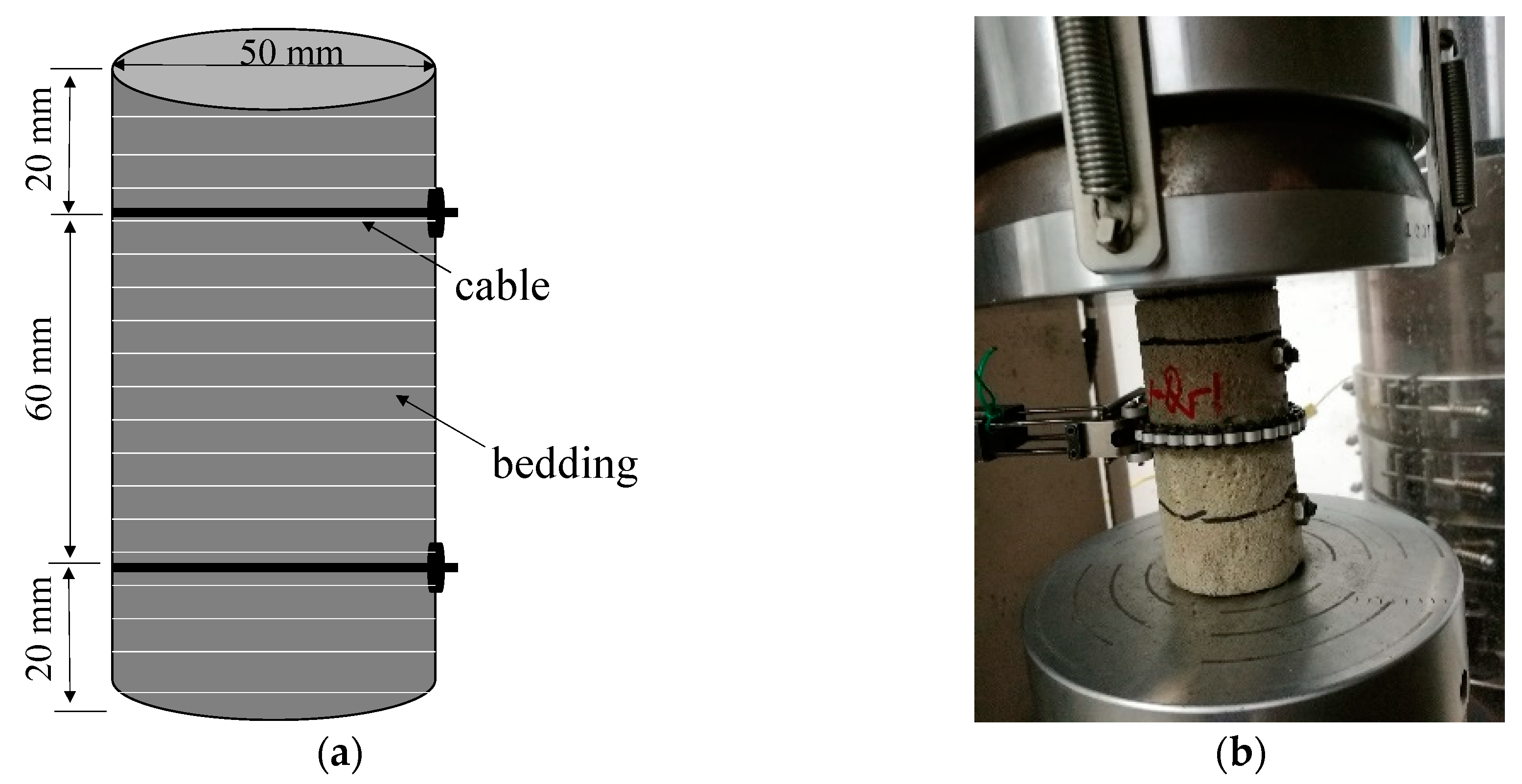
Figure 1. Uniaxial compression test: (a) Dimensions of an anchored specimen; (b) Test process.
Applsci 10 02329 g001
Figure 2. Schematic diagram of the strain gauge arrangement and an anchored specimen for shear testing: (a) Arrangement of the strain gauge; (b) Anchored specimen; (c) Test process.
Applsci 10 02329 g002
Figure 3. Stress–strain curve: (a) No anchoring; (b) End anchoring; (c) Full-length anchoring.
Applsci 10 02329 g003
Figure 4. Rock strength parameters by different anchoring methods: (a) Uniaxial compressive strength; (b) Elasticity modulus.
Applsci 10 02329 g004
Figure 5. Failure forms: (a) No anchoring; (b) End anchoring; (c) Full-length anchoring.
Applsci 10 02329 g005
Figure 6. Failure planes of anchored specimens: (a) End anchoring; (b) Full-length anchoring.
Applsci 10 02329 g006
Figure 7. Shear–displacement curves: (a) No bolt; (b) End anchoring; (c) Full-length anchoring.
Applsci 10 02329 g007
Figure 8. Shear force of the specimens by different anchoring methods.
Applsci 10 02329 g008
Figure 9. Strain distribution curves of the bolts.
Applsci 10 02329 g009
Figure 10. Field test: (a) Support parameters of the tunnel section; (b) Surrounding rock of the testing face.
Applsci 10 02329 g010
Figure 11. A measuring bolt.
Applsci 10 02329 g011
Figure 12. Section distribution and site installation of the measuring bolts: (a) Distribution of the measuring bolts; (b) Installation of the measuring bolts.
Applsci 10 02329 g012
Figure 13. Axial force (KN) distribution of the test section bolts: (a) ZK17+360 section; (b) ZK17+365 section.
Applsci 10 02329 g013
Figure 14. Arch crown settlement curve of the ZK17+365 section
Applsci 10 02329 g014
Table 1. Mechanical parameters of the bolt and screw.
Material Size/mmTensile Strength/MPaShear Strength/MPaAnchoring Force/MPa
Normal boltΦ16~22200~600260~600≥50
Selected screwΦ580040030~40