Featured Application
This paper describes the development of an automatic collet chuck holder prototype which was designed considering the proposed methodology and analytical models within novel systems in control of workpiece presence, control of workpiece position, control of clamping force and in its structure transmission. Results provide reliable theoretical and technical supports for optimization of the design and application of a collet chuck holder in high performance machining processes, inspection and quality control.
Abstract
In precision machining, expanding mandrels are used for jobs with close tolerances. An expanding mandrel consists of a tapered arbor or shaft, with a thin-slotted clamping sleeve or collet made of hardened steel. The internal tapered and external cylindrical surfaces are ground to a high degree of accuracy, and the mandrel expands to fit the internal bore of the workpiece. Expanding mandrels are, essentially, wedge mechanisms. This paper proposes an automatic expanding mandrel with a novel force transmission system for high stiffness within a novel air sensing system, which allows detection of the correct part position before starting machining. A computational model for determining the dynamic clamping force of the proposed mechanism is developed and implemented using MATLAB. This model considers the influence of the stiffness behaviors of the collet, force transmission structure and workpiece. Additionally, this paper presents the finite element method analyses which were conducted to check the proposed computational model. The amount of clamping force transmitted by a collet chuck holder depends strongly on: clearances, wedge angle, stiffness of the collet chuck holder and workpiece stiffness.
1. Introduction
Expanding mandrels are collet chuck holders, which are often used in turning, milling, grinding and inspection. These fixtures make it possible to clamp parts uniformly from the inside, so the outer surface is free to be machined. Commonly, expanding mandrels attached to a turning machine are used to perform secondary machining operations. High-speed cutting technology has increased the spindle rotational speed of machine tools, which implies that expanding mandrels must achieve high rotational speeds and at the same time maintain good rotational accuracy. Most of the expanding mandrels use solid thin-slotted clamping sleeves (collets) made of hardened steel and ground to a high degree of accuracy on their internal tapered and external cylindrical surfaces.
Tsutsumi [1] measured the clamping force of manual collet chuck holders in a static state by using a strain–gauges-based detector. Nevertheless, it was shown that manual collet chuck holders, with thin-slotted clamping sleeves, have poor repeatability of the clamping force distribution because they are manually operated. Schulz and Rondé [2] introduced a test stand for measuring torque transmitted by collets. They observed that for a degreased tool and collet, and friction coefficient of about 0.25, its uncertainty can be as high as 20%. For these reasons, collet chuck holders for high-speed or high-precision operation should have a wedge-actuated axial tightening system preventing distortions and thus improving concentricity and balancing conditions, as reported by Ema and Marui [3].
Rivin [4] describes a collet chuck design that uses a NiTi bushing in its clamping mechanism. Recently, Malukhin et al. [5] and Shin et al. [6] developed shape–memory alloy (SMA) tool clamping devices for micro machining. The tool clamp is simplified by using a collet with a SMA ring. The number of parts in the collet chuck is reduced and the errors in spindles due to stack-up tolerances are minimized. The analytical models used to explain the clamping–unclamping mechanisms are based on a conventional elasticity problem. Recent advancement in developments of strengthening models for nanostructured materials provide practical large-scale industrial applications in the field of collet chuck holders [7].
Nyamekye and Mudiam [8], Rahman and Tsutsumi [9] and Walter and Stähl [10] proposed models based on solid rigid theory to establish the loss of clamping force in lathe chucks due to centrifugal force and the main cutting force. According to these computational models, the loss of clamping force equals the total centrifugal force of the jaws. Due to the high centrifugal forces on the jaws that occur in high-speed turning, it is necessary to consider the behavior of the stiffness of the clamping systems when conducting the exact computation of the dynamic clamping force. Feng et al. [11] developed a mathematical model that considers the stiffness behaviors of the workpiece and the jaws to calculate the dynamic clamping force of jaw chucks during high-speed turning. This model was verified by means of finite element method (FEM) analyses and experimental investigations.
Because a collet chuck is basically a wedge mechanism, the static clamping force for a given acting force to the mechanism depends on the friction coefficients of the tapered and clamping surfaces, on clearance between the collet and the clamped part, and on collet stiffness [12,13,14,15,16,17].
Most expanding mandrels have complex parts in their transmission structure. This paper presents an automatic expanding mandrel design based on standard parts in its force transmission system (e.g., screws, rings, pins) with high stiffness behavior. The proposed expanding mandrel design provides an air sensing system that can detect the presence and the correct axial position of the workpiece.
As the joining of different materials is influenced by a range of parameters which are better recognized, monitored and optimized through both experimental and analytical methods [18,19], this paper presents an analytical model for determining the dynamic clamping force of the proposed expanding mandrel design based on solid rigid theory, elasticity and mechanical contact. The proposed analytical model takes stiffness behaviors into account and was implemented over Matlab. Finally, we present the FEM analyses that were conducted to check the proposed analytical model.
2. Expanding Mandrel Design
2.1. Acting Mechanisms
Automatic collet chucks are driven by two mechanisms: by pushing or by pulling. The operating principle of collet chucks is based on the wedge effect, as shown in Figure 1. The axial movement of the collet (2) or the cone (4) makes the jaws of the collet expand or contract, thus creating the clamping movement. Moreover, the applied axial force increases the normal force on the collet and thus the friction force and the maximum transmitted torque are also increased.
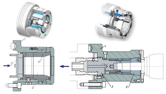
Figure 1.
Collet chuck acting by pushing and by pulling.
2.2. Structure of an Automatic Expanding Mandrel with Air Sensing System
Figure 2 shows an exploded view of the set in which standard parts (e.g., screws, cotter pins, gaskets) have been excluded. The section and transparent perspective with air sensing system ducts are shown. As shown in Figure 3, the acting piston (1) is coupled to a double-action cylinder in the machine by means of an adapter piece (2); both pieces have a central bore which is crossed by an air lance (3), which ends in a collecting chamber. Ducts from the collecting chamber allow the passage of compressed air to be used as a signal in the part presence detection and positioning system. The ducts end in three small bores at the front of the body (5), which also acts as a stop.
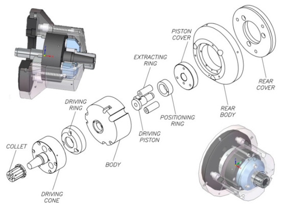
Figure 2.
Automatic expanding mandrel design.
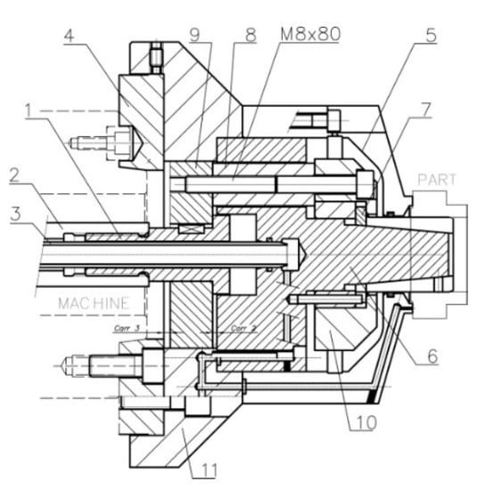
Figure 3.
Joint view section.
The collet (7) slides along the acting cone (6). The acting system by pulling (see Figure 3) consists of 3 extracting rings which are mounted to the inside of the rear part of the acting cone (6) with 3 M8 × 80 cap screws, 12.9 quality, in accordance with ISO 4762 and ISO 898-1, to the acting ring (10), and of the piston cover (9). The rear cover (4), which is coupled to the machine spindle nose via a short taper in accordance with ISO 702-1, also limits the stroke of the piston cover (9). The rear body (11) covers the acting system.
When the acting force provided by the machine actuator retracts the acting piston (1), the piston cover (9) retracts the screws (M8 × 80), so the acting ring (10) retracts the collet (7) and thus, the part is clamped. When the acting force pushes the acting piston (1), the piston cover (9) pushes the extracting rings (8), so the acting ring pushes the collet (7) and thus, the part is unclamped.
Materials of the automatic expanding mandrel main components (see Figure 2 and Figure 3) are summarized in Table 1.

Table 1.
Materials of the expanding mandrel.
3. Mechanical Analysis
Figure 4 shows the sequence of the proposed mechanical analysis.
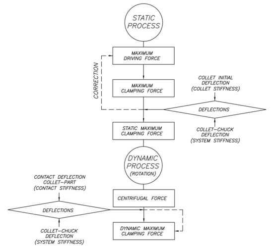
Figure 4.
Sequence of the mechanical analysis.
3.1. Maximum Acting Force Determination
As shown in Figure 5, the components which are subjected to the maximum tensile stress are the screws (M8 × 80). Thus, according to ISO 4762, 4010, 4014, 4017, 4032 and 898, the maximum force, Facc,max, which should be applied to each screw can be calculated by Equation (1), where S is the stress area, and σmax is the screw’s tensile stress.
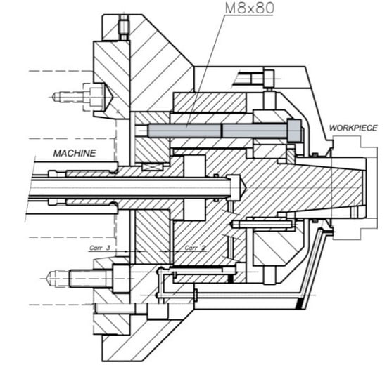
Figure 5.
Components subjected to the maximum tensile stress.
3.2. Maximum Clamping Force Determination
A two-dimensional model is used to mathematically describe the basic principle of automatic chuck holders (see Figure 6). This model assumes a uniform distribution of the contact pressure p, a condition that is only satisfied when both tapered contact surfaces have the same length. Thus, the normal force Fn can be computed as the integral of the contact pressure p between the maximum and the minimum radius of the tapered collet surface, as shown in Equation (2). In this equation, rs is the maximum radius, ri is the minimum radius and r is the radius of the area element dA. Normal wear (Sn) is assumed to be uniform for all points of the tapered surface. Consequently, the maximum pressure occurs for the minimum value of the radius ri in Equation (3).
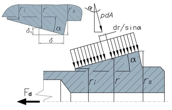
Figure 6.
Cone–collet contact pressure.
The second contact occurs between the collet and the workpiece as shown in Figure 7. In order to compute the forces and the slippage moment, it is considered that the pressure transmitted for each jaw is equal and constant. The clamping force Fs is calculated in Equation (5) and used in Equation (6) to obtain the frictional force FR and in Equation (7) to obtain the total force FT. The slippage moment Mt is calculated by using Equations (8) and (9), where μcw is the friction coefficient between the collet and the workpiece.
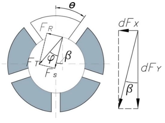
Figure 7.
Contact pressure and forces on collet workpiece.
The total clamping force, Fs in Equation (5), needed to clamp the workpiece sufficiently should also be of sufficient magnitude to resist slippage of the clamped workpiece under the influence of the torque, Mt in Equation (10), generated by the expected main cutting force, Fc in Figure 8. The feeding force Fv is mainly absorbed by the mandrel body, which acts as a stop and reference surface, and the force Fp is absorbed by the collet. In this study, the effects of these two forces are neglected.
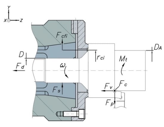
Figure 8.
Forces acting in collet chuck holders.
3.3. Tolerance Analysis
The radial deflection of the spring collet jaws is so small that it is comparable to the manufacturing tolerances. Therefore, the tolerances must be known precisely to predict the clamping force.
The tolerances of the workpiece and the collet define the maximum and minimum clearances. The relationships to calculate these tolerances are expressed in Equations (11) and (12). However, the outside diameter of the collet must be equal to the inside diameter of the clamped workpiece in its working state (see Figure 9).
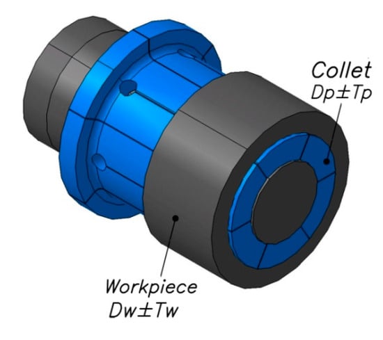
Figure 9.
Tolerances of the collet and the workpiece.
3.4. Collet Initial Deflection
Each jaw is fixed to the root of the collet, so it can be considered as a cantilever as shown in Figure 10. By using classical elasticity theories, the maximal deflection ε produced by the clamping force Fs is estimated (see Equation (13)). The radial stiffness of the collet, kR, is given by Equation (14). Equation (15) gives the expression to compute the clamping force Fs2, which is used to deform the collet. This allows one to calculate the needed increase in the acting force using Equation (4).
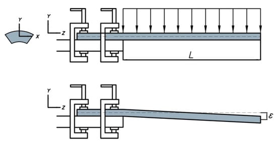
Figure 10.
Equivalent representation of a jaw of the collet.
3.5. Collet Chuck Stiffness Due to Clamping Force
The total clamping force generates a lateral bend and a radial deflection at the clamping position. Since a collet chuck holder is mainly composed of an acting cone, a collet and a piston, the stiffness behavior of the collet chuck transmission system can be described with two parameters each for the collet chuck and the collet stiffness:
- Radial stiffness of chuck acting system, kr,s in N/μm, measured at its center position. The chuck acting system comprises a piston and a cone.
- Bending stiffness of chuck acting system, kf,s in Nm/μm/m.
- Radial stiffness of collet jaw, kr,p in N/μm, measured at the bottom position of collet jaw.
- Bending stiffness of collet jaw, kf,p in Nm/μm/m.
The radial deflection at the clamping position due to the total clamping force involves four components, shown in Figure 11:
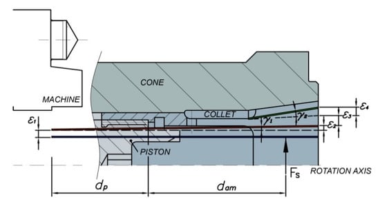
Figure 11.
Deformation of collet chuck due to total clamping force.
- Radial deflection of collet chuck holder, ε1.
- Radial deflection due to the bending of collet chuck holder, ε2.
- Radial deflection of collet jaw relative to chuck acting system, ε3.
- Radial deflection due to the bending of collet jaw relative to chuck acting system, ε4.
The radial stiffness at the clamping position, kr,T, is computed by using the Equation (16).
Deflections at the clamping position can be analytically determined by the equations summarized in Table 2. The distances dp and dam are also shown in Figure 11.
Table 2.
Deflections of collet chuck due to clamping force.
Substituting the equations summarized in Table 2 into Equation (16) yields Equation (17).
3.6. Collet Chuck Deflection Due to Centrifugal Force
The variation in the clamping force, Fs3, due to centrifugal force Fcen on each of the collet jaws, and on the transmission system, is calculated by Equation (18), where Fse is the preset static clamping force before the collet chuck has been rotated, calculated using Equations (5), (13) and (15); “+” indicates external clamping and “−“ indicates internal clamping.
As shown in Figure 12, the centrifugal force Fi of the element “i” is computed as a function of the rotational speed n, the mass mi and the radius of the mass center rci, where i = cn, pt or pn (which represent transmission system, piston, and collet, respectively), by Equation (19).
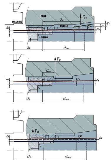
Figure 12.
Centrifugal forces and distances at clamping position.
Due to the different positions of the components, the centrifugal forces cause different radial stiffness and thus, a radial deflection at the clamping position. As such, the total radial stiffness of the collet chuck for each centrifugal force, kr,Tj, is given by Equations (20)–(22).
The different amounts of deflection at each clamping position caused by centrifugal forces can be determined by the equations summarized in Table 3.
Table 3.
Deflections of collet chuck due to centrifugal forces.
Substituting the equations summarized in Table 3 into Equations (20)–(22) yields Equations (23)–(25).
By assuming the loss of clamping forces ΔFs and the centrifugal forces Fi are always equal on the collet side and on the workpiece, we have Equation (26).
Figure 13 shows the diagram used to determine the variance in the clamping force depending on the stiffness of the collet chuck or expanding mandrel and the workpiece.
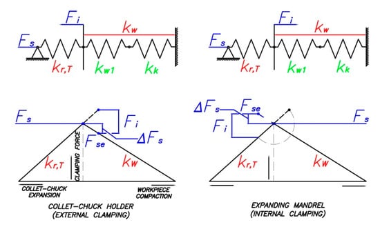
Figure 13.
Diagram for determining the variance in the clamping force.
In Equation (26) and in Figure 13, kw is the radial workpiece stiffness. In addition to the ideal radial stiffness kw1, the contact stiffness between the collet jaws and the workpiece kk must be considered as shown in Equation (27).
Collet, transmission, piston and contact stiffness between the workpiece and collet jaws were determined using the finite element (FE) models proposed in this paper.
4. FE Analysis of Clamping Force
For performing the simulations using FEM, 2 commercial packs (ALGOR and CATIA) were used considering all parts, the collet, acting cone and workpiece shown in Figure 14a. The 3D model was homogeneously meshed with 10-node tetrahedral elements shown in Figure 14b. The types of steel chosen are summarized in Table 1. For the sake of simplicity, we considered the materials were perfectly plastic and used the von Mises criterion. A Cartesian coordinate system (X, Y, Z) was used as shown in Figure 14c,d. All simulations were performed considering an expanding mandrel driven by pulling, with dimensions shown in Figure 15.
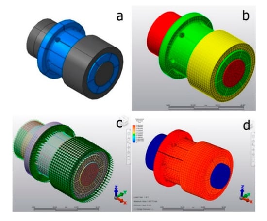
Figure 14.
Proposed Finite Element model in ALGOR.
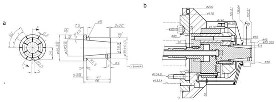
Figure 15.
Special expanding mandrel dimensions: (a) collet, (b) acting system.
Two different types of simulations were carried out. The first case, without rotation, was analyzed where the collet and acting cone were placed in the final clamped position. The simulations were carried out considering Coulomb friction between the two bodies, characterized by a dynamic friction coefficient, μ = 0.09. Thus, nonlinear analysis must be considered in numerical simulations due to the contact nature of the problem or the possibility of plastic deformation during the clamping process.
The second type of simulation, shown in Figure 16, corresponds to the dynamic process with rotational speed n = 2000 r/min. For both types of simulations, the acting forces Fj, applied in the longitudinal direction of the collet, varied from 25 to 9000 N, and the end of the acting cone was fixed as shown in Figure 14c.
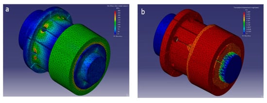
Figure 16.
Proposed finite element model in CATIA®. Results of (a) stress and (b) displacements.
The 3D FE models consisted of a workpiece, collet and cone. The workpiece stiffness could be changed according to its material properties. The contact stiffness between the workpiece and collet jaws was computed and simulated using contact elements.
5. Evaluation
Several experiments were conducted to verify the feasibility of the automatic expanding mandrel.
5.1. Collet Initial Deflection
Figure 17 compares the amount of the acting force needed to deform the collet obtained from the FE model and from Equations (11) and (12). The value of the collet radial stiffness, kR, can be obtained from Equation14 or from the slope of the resulting straight.
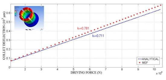
Figure 17.
Collet deflections: analytical and finite element analysis.
5.2. Expanding Mandrel Deflection
The loss of clamping force, taking into account the influence of the collet chuck and workpiece stiffness derived from Equations (26) and (27), is given by Equation (28).
A dimensionless parameter ψ is defined according to Equation (29) for better comprehension of the analysis results.
5.3. Variance of the Clamping Force
Figure 18 shows the influence of the expanding mandrel stiffness kr,T. An increase in kr,T results in an increase in radial stiffness at the clamping position and therefore, the chucking accuracy is improved. Meanwhile, greater expanding mandrel stiffness contributes to a greater PSI factor, resulting in a minor effective centrifugal force at the clamping position. As such, it is obvious that an increase in kr,T always has influence in reducing the variance of clamping force. The radial stiffness of the collet chuck can be effectively changed by optimizing the chuck structure, particularly the structure of the transmission system. However, it should be taken into account that the lower the workpiece stiffness, the higher the variance of the clamping force.
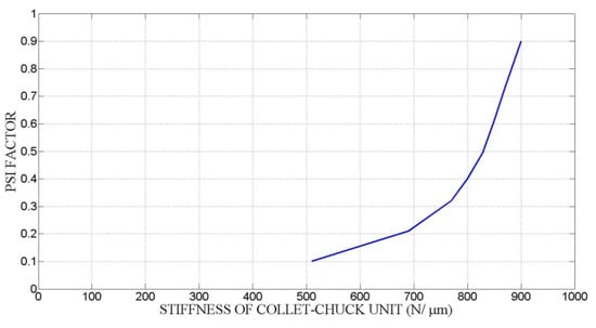
Figure 18.
Influence of the stiffness of expanding mandrel and workpiece.
Figure 19 shows the computation of the clamping force variance, taking into account the expanding mandrel prototype stiffness as shown in Figure 20. Low workpiece stiffness and high expanding mandrel stiffness provide a reduction in the variance of the clamping force.
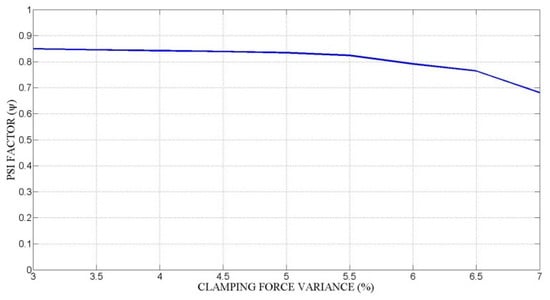
Figure 19.
Variance of clamping force.
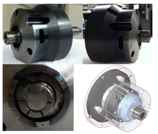
Figure 20.
Expanding mandrel prototype within the air sensing system.
5.4. Stress throughout Contact between Cone and Collet
A dimensionless parameter t is defined according to Equation (30) for a better comprehension of the analysis results, where La is the cone length in contact with the collet at any time, and Lb is the total length of the collet. Obviously, 0 ≤ t ≤ 1.
The maximum value of the ratio, defined by Equation (31), where σvm is the von Mises stress and Si is the cone and collet yield stress, would not be more than 1.
As can be observed from the results of the stress experiment shown in Figure 21, at points placed at the edge of the collet’s lateral holes, there is a sudden increase in their von Mises ratio. At other points, the collet and the cone do not exhibit such sharp changes.
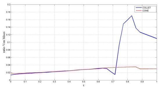
Figure 21.
von Mises stress distribution ratio for cone–collet.
5.5. Stress throughout Contact between Collet and Workpiece
For the von Mises stress, the simulation has led to the distribution shown in Figure 22. For the workpiece, the evolution of the von Mises stress with the clamping process is highly uniform, and the maximum values are far from the material yield stress at any time. For the collet, the stresses generated by the clamping process appear at the closest zone to the extreme of the collet and at the extremes of the collet holes. Stresses are not significant at any point by the end of the clamping process.
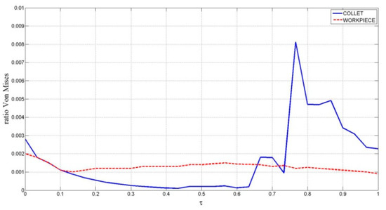
Figure 22.
von Mises stress throughout contact between collet and workpiece.
6. Conclusions
In this paper, we present an automatic expanding mandrel with a novel force transmission system, with high stiffness using a novel air sensing system. We have also developed a computational model implemented in Matlab for determining the dynamic clamping force of the proposed design, which takes into account the influence of the stiffness behaviors of the collet, force transmission structure and workpiece.
The amount of clamping force transmitted by a collet chuck holder depends strongly on:
- Clearances determined by the tolerances of the collet and the workpiece as well as of the collet’s initial static stiffness.
- Wedge angle. Decreasing the wedge angle will increase the mechanical advantage and thus the transmitted clamping force; however, this will result in an exponential increase in the tension experienced by the collet.
- Stiffness of the collet chuck holder. A collet chuck holder with higher structural stiffness, particularly in its force transmission system, requires less acting force and therefore has a more effective force transmission system.
- Workpiece stiffness. Workpieces with lower stiffness reduce the loss in clamping force provided by collet chuck holders.
7. Patents
A Spanish patent resulting from the air sensing device reported in this manuscript is under number ES2413910.
Author Contributions
The authors made most of the contributions regarding conceptualization, development of theory, validation, verification of the analytical models, discussion of the results, as well as the final manuscript. Individual contributions are as follows: introduction, methodology, visualization and original draft preparation: E.S.H., H.R. and J.C.G.P.; review, editing, validation and formal analysis: E.S.H., H.R. and A.B.; supervision: J.C.G.P. All authors have read and agreed to the published version of the manuscript.
Funding
This research received no external funding.
Conflicts of Interest
The authors declare no conflict of interest.
References
- Tsutsumi, M. Chucking force distribution of collet chuck holders for machining centers. J. Mech. Work. Technol. 1989, 20, 491–501. [Google Scholar] [CrossRef]
- Schulz, U.R. Parameters to describe the behavior of clamping means of tools with parallel shanks. Prod. Eng. 1994, 99, 102. [Google Scholar]
- Ema, E.M. Chucking performance of a wedge-type power chuck. Trans. ASME J. Eng. Ind. 1994, 116, 70–77. [Google Scholar] [CrossRef]
- Rivin, E.I.; Agapiou, J.; Brecher, C.; Clewett, M.; Erickson, R.; Huston, F.; Kadowaki, Y.; Lenz, E.; Moriwaki, T.; Pitsker, A.; et al. Tooling structure: Interface between cutting edge and machine tool. CIRP Ann. 2000, 49, 591–634. [Google Scholar] [CrossRef]
- Malukhin, K.; Sung, H.; Ehmann, K. A shape memory alloy based tool clamping device. J. Mater. Process. Technol. 2012, 212, 735–744. [Google Scholar] [CrossRef]
- Shin, W.-C.; Ro, S.-K.; Park, H.-W.; Park, J.-K. Development of a micro/meso-tool clamp using a shape memory alloy for applications in micro-spindle units. Int. J. Mach. Tools Manuf. 2009, 49, 579–585. [Google Scholar] [CrossRef]
- Tian, L.; Li, L. A review on the strengthening of nanostructured materials. Int. J. Curr. Eng. Technol. 2018, 8. [Google Scholar] [CrossRef]
- Nyamekye, K.; Mudiam, S.S. A model for predicting the initial static gripping force in lathe chucks. Int. J. Adv. Manuf. Technol. 1992, 7, 286–291. [Google Scholar] [CrossRef]
- Rahman, M.; Tsutsumi, M. Effect of spindle speed on clamping force in turning. J. Mater. Process. Technol. 1993, 38, 407–415. [Google Scholar] [CrossRef]
- Walter, M.F.; Ståhl, J.E. The connection between cutting and clamping forces in turning. Int. J. Mach. Tools Manuf. 1994, 34, 991–1003. [Google Scholar] [CrossRef]
- Feng, P.F.; Yu, D.W.; Wu, Z.J.; Uhlmann, E. Jaw-chuck stiffness and its influence on dynamic clamping force during high-speed turning. Int. J. Mach. Tools Manuf. 2008, 48, 1268–1275. [Google Scholar] [CrossRef]
- Soriano, E.; Ramírez, M.B.; Rubio, H. Model for determining the clamping force in expanding mandrels for high-speed turning. Int. Rev. Mech. Eng. 2012, 6, 384–389. [Google Scholar]
- Soriano, E.; Rubio, H.; García-Prada, J.C. Analysis of the Clamping Mechanisms of Collet-Chucks Holders for Turning; Springer: Berlin, Germany, 2013; pp. 391–398. [Google Scholar]
- Soriano, E.; Rubio, H.; García-Prada, J.C. Models for Determining the Static Stiffness of Collet Sleeves; Springer: Berlin, Germany, 2014; Volume 17. [Google Scholar]
- Ram Prasad, S.; Pravin Kumar, N. Structural Optimization of ER Spring Collet for Maximized Gripping Action. Int. J. Eng. Sci. Comput. 2017, 7, 12638–12642. [Google Scholar]
- Michopoulos, J.G.; Iliopoulos, A.P.; Steuben, J.C.; Graber, B.D. Design of NRL66.4: An electro-hydraulic 6-DoF parallel robotic multiaxial material testing system. In Proceedings of the 39th Computers and Information in Engineering Conference, Anaheim, CA, USA, 18–21 August 2019; Volume 1. [Google Scholar]
- Redko, R.; Zabolotnyi, O.; Redko, O.; Savchuk, S.; Kovalchuk, V. Improvement of Manufacturing Technology and Recovery of Clamping Collets for Lathe Automats; Springer: Berlin, Germany, 2020; pp. 290–301. [Google Scholar]
- Çam, G.; Koçak, M. Progress in joining of advanced materials. Int. Mater. Rev. 1998, 43, 1–44. [Google Scholar] [CrossRef]
- Khoddam, S.; Tian, L.; Sapanathan, T.; Hodgson, P.D.; Zarei-Hanzaki, A. Latest developments in modeling and characterization of joining metal based hybrid materials. Adv. Eng. Mater. 2018, 20, 1800048. [Google Scholar] [CrossRef]


© 2020 by the authors. Licensee MDPI, Basel, Switzerland. This article is an open access article distributed under the terms and conditions of the Creative Commons Attribution (CC BY) license (http://creativecommons.org/licenses/by/4.0/).