4.2. Interface Damage Analysis under Uniform Temperature Load
In this case, the initial temperature of each layer was the same and varied synchronously. Under uniform temperature load, the under-rail structural layers exhibited a uniform longitudinal and transverse deformation trend. As the displacements of layers were constrained and thermal expansion coefficients of asphalt concrete and cement concrete were different, there was a relative movement trend between the two layers and shear stress occurred at the interface. When shear stress exceeded the interface bonding strength, shear failure occurred at the interface and the restraint effect of ACWL on the cement base plate failed. The results of previous numerical calculations prove that the bonding performance of the interface between CCBP and ACWL is consistent with each other under the uniform rise and drop in temperature load. Therefore, herein, the evolution process of interfacial bond-slip behavior under uniform rising temperature load is analyzed.
The initial temperature was set as 15 °C, and the temperature rising ranges () were 1, 5, 10, 15, 20, 30, and 40 °C, respectively. To investigate the required to achieve complete debonding state, 50 °C and 60 °C rising ranges were also employed. The indicators that characterized interface state included shear stress, an index for the interlayer damage initiation (QUADSCRT), and an index for damage degree (SDEG).
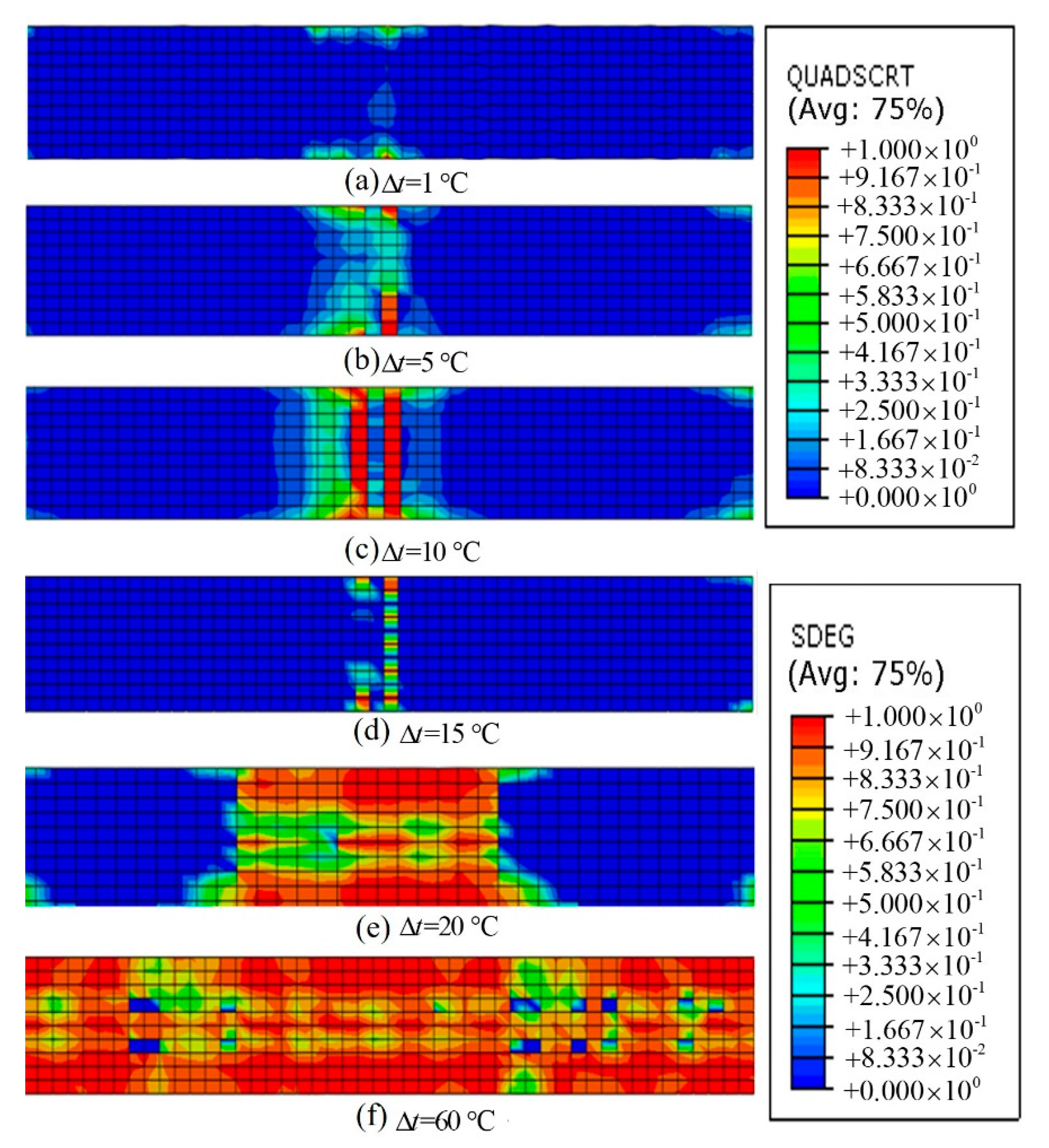
Figure 7 shows the contour of damage indices (QUADSCRT and SDEG) under different temperature loads. The interface damage evolution process can be divided into four stages. At the first stage (
), damage accumulated at the interface and interface crack did not yet occur. At the second stage (
), QUADSCRT reached 1 and interface microcracks generated at the expansion joint, but the maximum value of SDEG was still lower than 1 which meant there were no macrocracks generating at the interface. At the third stage (
), SDEG at the expansion joint reached the maximum value first, and macrocracks started to generate at the expansion joint and propagated to the other areas of the interface. Finally, when the temperature rising range exceeded
, the adjacent layers were totally delaminated and interface contact state turned into sliding friction (see
Figure 7f).
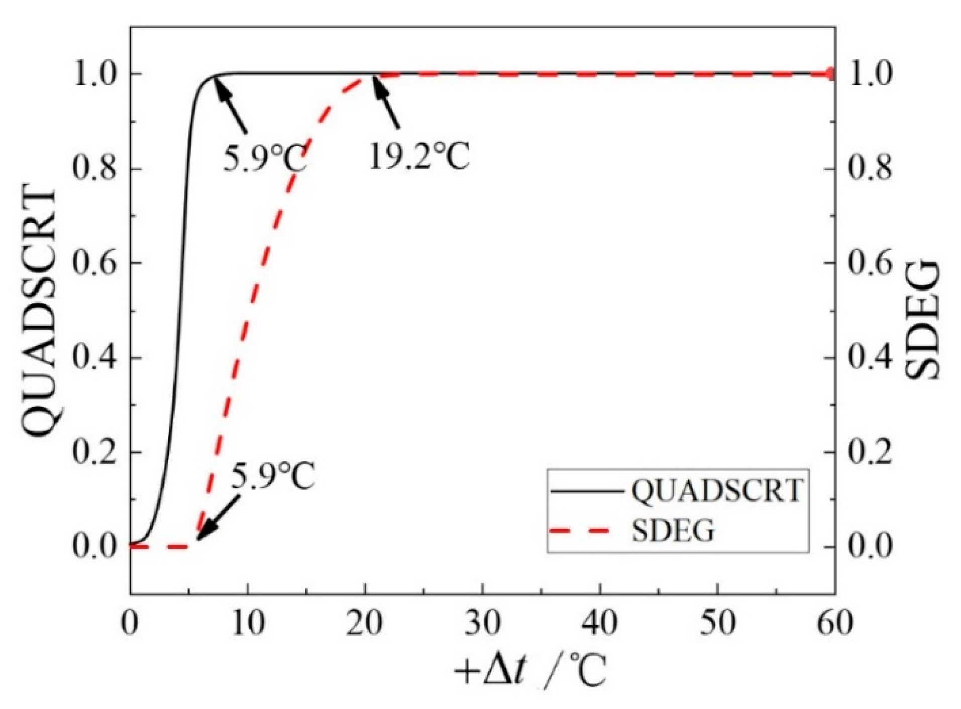
As shown in the contour of damage indices, the interface under the expansion joint of the base plate was the most vulnerable area under temperature loads. The variation of QUADSCRT and SDEG at the expansion joint with
is plotted in
Figure 8. The variation of interface damage ratio and detachment area ratio with
is presented in
Table 4. Interface damage ratio is the percentage of damaged area (QUADSCRT = 1 and SDEG > 0) in the total area. Detachment area ratio is the percentage of delaminated (SDEG = 1) in the total area. When
, QUADSCRT at the expansion joint increased to 1, suggesting that the interface microcracks started to generate. When
was 19.2 °C, interface macrocracks initiated and propagated. From the initiation of interface microcracks to the initial debonding of the adjacent layers, the temperature increase was about 13.3 °C. The temperature rising range was 45.8 °C for the macrocracks to expand completely and the whole interface to delaminate.
Then, the interface under the expansion joint of the base plate was selected as the research object—the effect of interface parameters and temperature loads on the interface cracking performance was analyzed. The interface parameters included interfacial shear strength, interfacial shear stiffness, and critical fracture energy, and their values are listed in
Table 5. When analyzing the impact of one parameter, the other parameters, in the middle column of
Table 5, are the corresponding values.
The variation curve of the QUADSCRT index at the adjacent joint under different working conditions with the temperature rising range is plotted in
Figure 9. As shown in
Figure 9a,
needed for the initiation of interface damage (microcracks) increased with the increase in interfacial shear strength, but
needed for the initiation of macrocracks was not impacted by the interfacial shear strength. Also, the slopes of the QUADSCRT temperature rising range curves in
Figure 9a indicate that the larger the interfacial shear strength, the faster the interfacial damage propagation rate. Increasing the interfacial shear strength is conducive to the stability of the whole structure.
needed for the initiation of microcracks decreased as the interfacial shear stiffness increased, while
needed for macrocrack initiation remained unchanged (
Figure 9b). These results indicate that an increase in interfacial shear strength makes the interfacial damage (microcrack) more sensitive to the temperature changes, but has a little influence on the initiation behavior of interfacial macrocracks. As shown in
Figure 9c, with an increase in the critical fracture energy,
needed for initiation of the interface damage remained unchanged, while
needed for the macrocracks’ initiation increased. One effective way to reduce the sensitivity of the interfacial macrocracks to temperature changes is to increase the interfacial critical fracture energy.
As per the above analysis, the interface with larger interfacial strength and toughness has a smaller damage area. The greater the interfacial stiffness, the stronger the interaction between adjacent layers and the easier the generation of interface damage. Therefore, appropriate material and necessary measures (such as toughening by brushing) should be adopted in the construction of asphalt concrete layer to guarantee excellent strength and toughness at the interface, in order to enhance the deformation coordination ability between CCBP and ACWL, especially in the shear direction. During the maintenance stage, patching material with high strength, high toughness, and lower stiffness should be selected. Meanwhile, measures (such as laying geotextiles, etc.) should be taken to reduce the interface stiffness and alleviate the initiation possibility of interface damage at the expansion joint of the base plate, which is more prone to interface damage.
4.3. Interface Damage Analysis under Gradient Temperature Load
Because of large annual/daily temperature difference in Northern China and poor thermal conductivity of concrete materials, the seasonal changes in atmospheric temperature can result in a gradient temperature field in the ballastless track. Under the action of gradient temperature, the interface damage caused by the relative displacement trend of the adjacent layers accumulates. Therefore, this section analyzes the evolution process of the interface-bond-slip behavior between ACWL and CCBP under positive and negative gradient temperature loads.
According to the recommended value in the “Code for Design of High Speed Railway” in China (TB10621-2014), the positive temperature gradient load (the upper layer is hotter than the lower layer) was set as 90 °C/m, and the negative temperature gradient in track slab (the upper layer is colder than the lower layer) was set as 45 °C/m, respectively. Although the temperature gradient was negligible in the layers that are over 0.2 m in depth from the track slab surface, 10 °C/m was set in the cement base plate for design security. The temperature gradient in layers below the base plate was not set.
The effect of coupled action of gradient and uniform temperature loads on the interfacial characteristics was also analyzed. The details of the simulation cases are listed in
Table 6.
As shown in
Figure 10, in cases 1 and 2, only a few interface microcracks were generated at the expansion joint of the base plate and the damage area was extremely small. The positive/negative gradient temperature load had little effect on the interface between CCBP and ACWL. The transverse and longitudinal shear stress and normal displacement at the interface between CCBP and ACWL in cases 1 and 2 are listed in
Table 7. The deformation of the interface was tiny and the stress between the adjacent layers was smaller than the designed strength, which signifies that the ballastless track structure was safe under a 90 °C/m positive gradient temperature load and a 45 °C/m negative gradient temperature load.
The relationship curves of QUADSCRT/SDEG and temperature rising/dropping range (
) in cases 3~6 are plotted in
Figure 11. As shown in
Figure 11a, when the initial temperature load was 90 °C/m (positive), the microcracks started to generate when
was 5.5 °C and macrocracks occurred when
. When the temperature was reduced and the initial temperature gradient was 90 °C/m (positive), the microcracks started to generate when the temperature dropping range was 7.7 °C. The interface started to debond when the temperature dropping range was 20.8 °C (
Figure 11b). As depicted in
Figure 11c, when the negative gradient temperature load and the global warming load worked together, the interface microcracks started to generate when
was 7.4 °C and the interface started to delaminate when the temperature dropping range was 20.5 °C. As shown in
Figure 11d, when the negative gradient temperature load and the overall cooling load worked together on the structure, the interfacial microcracks started to generate when the temperature dropping range was 5.3 °C and the macrocracks generated when the dropping range was 18.6 °C.
By comparing
Figure 9 and
Figure 11a,b, the initiation of interface microcracks and interface macrocracks was exacerbated under the combined action of a positive gradient temperature load and global warming load, but they were delayed under the combined action of a positive gradient temperature load and global cooling load. By comparing
Figure 9 and
Figure 11c,d, the initiation of interface microcracks and interface macrocracks was exacerbated under the combined action of a negative gradient temperature load and global cooling load, but they were delayed when the loading state was a negative gradient temperature load and global cooling load.
4.4. Dynamic Characteristics of the Ballastless Track with Interface Damage
The effect of existing interface damage on the safety and stability of high-speed railway operation is worth exploring. In this case, the quasi-static damage analysis of the ballastless track under temperature load was performed first to obtain the initial state of the track structure. Then, the train vibration load was applied on the rails to analyze the dynamic response of the ballastless track with three interface contacting conditions of CCBP and ACWL including the perfect bond state, partly damaged but no slippage state (), and the sliding friction contact state. The tensile strain, vertical deformation in ACWL, and dynamic stress in the surface layer of the road bed were selected as the indices.
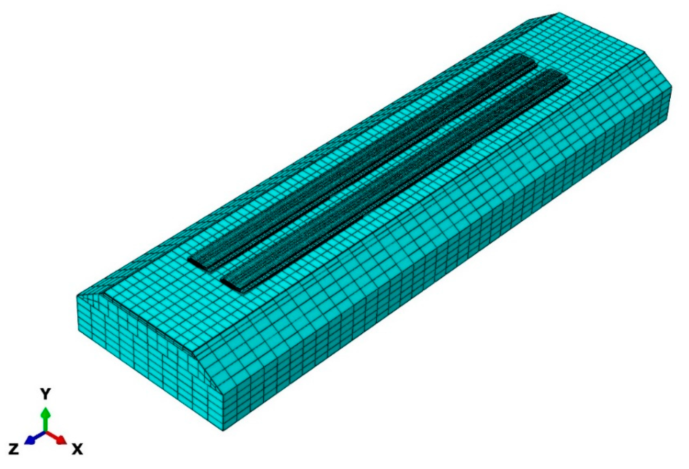
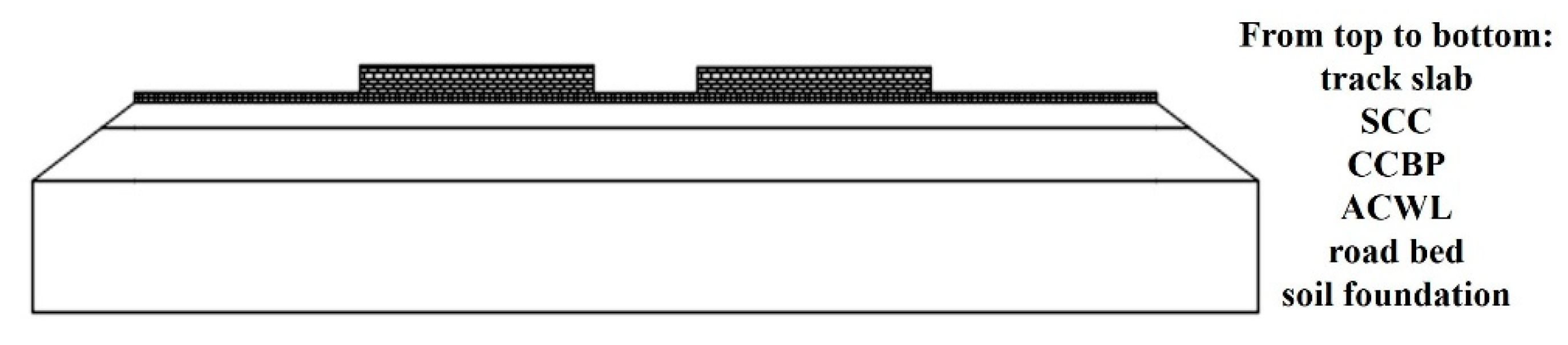
In this section, a three-dimensional finite element model of a ballastless track structure containing the rails and fasteners was established. This structure was composed of CHN60 rails, a fastener system, track slab, self-compacting concrete (SCC), CCBP, ACWL, road bed, and soil foundation. The CHN60 rails were modelled by Euler beam element. The fastener system was modelled by spring-damper elements. The vertical and transverse stiffness of the fasteners and pads were 70 KN/m and 30 KN/m, and the vertical and horizontal damping were 60 and 50 , respectively. The geometries and the material parameters of other components and the model constraints were the same as the former model.
The train vibration load is regarded as a periodic moving load and simplified to a sine function, as shown in Equation (5).
where
is the train vibration load,
is the static wheel load, 130 KN,
is the vibration load,
,
is the unsprung mass of the train, 750 kg,
is the height of geometric irregularity, 0.6 mm,
is the circular frequency of the vibrating wavelength,
,
is the train speed, 350 km/h, and
is the wavelength of geometric irregularity curve, 2 m.
The train vibration load was applied on the rails at the joint of the adjacent track slab (case 1) and the center of the base plate (case 2), respectively. The calculation results of dynamic responses are summarized in
Table 8.
As shown in
Table 8, the dynamic indices at the adjacent joint and the center of base plate were almost the same. The interface contact state had a great impact on the dynamic response of the whole structure under the train loads. Compared with the perfectly bonded state, for the state where few interface microcracks existed, the transverse tension strain of ACWL was about ten times that of the previous state, while the longitudinal tension strain and the vertical stress in the surface layer of subgrade were about 10 times and 2 times that of the previous state, respectively. When the interface was totally unbonded, the transverse and longitudinal tension strain and vertical displacement of asphalt layer surface were about 134, 50, and 24 times that of the original state. The interface damage had a great influence on the dynamic response of the ballastless track.


