Review

A Survey of Optimal Hardware and Software Mapping for Distributed Integrated Modular Avionics Systems

1
School of Computers, Guangdong University of Technology, Guangzhou 510006, China
2
School of Automation, Guangdong University of Technology, Guangzhou 510006, China
3
Computing Science Department, Institute of High Performance Computing (IHPC), Agency for Science, Technology and Research (A*STAR), Singapore 138632, Singapore
*
Author to whom correspondence should be addressed.
Appl. Sci. 2020, 10(8), 2675; https://doi.org/10.3390/app10082675
Submission received: 20 February 2020 / Revised: 2 April 2020 / Accepted: 6 April 2020 / Published: 13 April 2020

Abstract

:
With an increasing number of aircraft systems, a fully manual developmental approach is impractical for finding optimal hardware and software mapping from overwhelming configurations for Distributed Integrated Modular Avionics (DIMA) systems. The automation of finding such optimized mapping should be available and thoroughly understood. This paper is an investigation on the foundations of optimal hardware and software mapping for DIMA. We begin by reviewing the DIMA system architecture. Following that, we present the problem statement of hardware and software mapping and its ensuring mathematical optimization models. A set of primary architectural quality metrics (e.g., reliability and scalability) and aircraft constraints (e.g., segregation and resource constraints) are identified, which can be used to compose an objective function or compare and trade alternatives. Based on the quality metrics and aircraft constraints, we synthesize an encompassing formulation by means of multi-objective optimization. Various optimization approaches for hardware and software mapping are then reviewed and compared. Case studies of DIMA optimization are presented for avionics systems, in which running time is reported for different optimization problems with different objectives and constraints. In addition, we present and discuss open issues and future trends, from which future developments may draw upon.

1. Introduction

Since the introduction of modern avionics into civil and military aircraft, avionics systems have evolved from analogue radio communication and navigation systems developed around World Wars I and II [1,2,3] to digital, multi-functional, integrated and distributed systems of the present. The growing demand for increasingly smarter functionality of aircraft systems has promoted the need for more powerful avionics [4]. This has been fueled by the introduction and fast evolution of digital electronics, allowing great improvement in accuracy and performance while also enabling new avionics architectures [5].
One of the most recent manifestations of avionics system is Distributed Integrated Modular Avionics (DIMA). DIMA is an evolution of Integrated Modular Avionics (IMA) concept [6]. Centered upon the idea of shared resources and standardized components, IMA is a safety-critical modular computational platform for the execution of software-implemented aircraft systems; Airbus A380 and Boeing 777 are in the category of IMA. While IMA was conceived around a single cabinet housing all shared computational resources, DIMA extends IMA to allow their distribution throughout the aircraft [7]; typical aircraft models include Airbus A350 and Boeing 787. It provides greater flexibility for designers, thus allowing to better address user and engineering needs.
The design flexibility of DIMA systems comes at the price of overwhelming configurations. Two levels of mappings [8,9] are usually considered: (1) software modules to hardware components, and (2) hardware components to installation locations. For the software mapping, system functions in the form of software modules must be allocated to hardware components (also referred to as DIMA devices) while considering device capabilities (i.e., resources provided by the specific hardware) and relevant constraints (e.g., segregation). For the hardware mapping, DIMA devices must be assigned to installation locations that are restricted in volume, electrical power, and network connectivity. Finding valid mappings is not sufficient; the system is expected to be optimized. However, achieving global optimum for both mappings simultaneously is usually challenging. Typically, the combinatorial explosion of design choices for the mappings raises the concern on how to compare alternatives and ultimately perform decisions efficiently and effectively. In the current state of affairs, with an increasing number of software-implemented aircraft systems, a fully manual developmental approach is impractical. Although some attempts have been made to conduct configuration engineering [10,11], develop testing framework [12] and analyze the schedulability of DIMA [13,14,15,16], automatic optimization is still desired to obtain optimal configurations. It is therefore paramount that a comprehensive framework for automating the construction of optimized mapping should be available and thoroughly understood [17].
In this paper, we survey the fundamental landscape for optimization of DIMA systems. We begin by presenting the DIMA system, which consists of three hierarchical layers. We then visit the problem statement of hardware and software mapping, and how it can be translated into a mathematical model. The generic mapping problem is equivalent to the general assignment problem of optimal resource allocation in distributed computing. This is commonly formulated as an integer linear program, and solved through approximate or heuristic algorithms. We refer to such a problem of finding the optimal mapping as DIMA optimization. We review the literature and enumerate the existing approaches for solving this class of problems, and compare the different approaches, including standard solvers (e.g., WebSphere ILOG CPLEX [18] and GUROBI [19]), and metaheuristic methods (e.g., genetic algorithms). Particularly, we investigate multi-objective optimization approaches in depth, due to the conflicting nature of typical performance measures. Case studies for both single objective and multi-objective optimizations are provided. The running time of various objective functions and constraints differs from each other; it depends on what sort of optimization problem is to be solved and what sort of optimization method is to be leveraged. For the multi-objective optimization, its running time is orders of magnitude above that of single objective optimization. Finally, we present future trends and orbiting research topics that are increasingly relevant for DIMA optimization.
There are a few survey papers on avionics systems and DIMA, but neither of them cover the DIMA optimization. Some of them focus on network communication systems [20,21,22] or structural optimization [23] in the aerospace field. A much more relevant work is given by Reference [24] that provides a review on key technologies of DIMA, particularly in task scheduling, but the scheduling is conducted in a fixed hardware and software mapping. This survey paper focuses on DIMA optimization for the optimal configuration, which should be useful especially for avionics architecture designers. Given a particular aircraft specification and the desired performance measures, designers may derive insights for the selection of an optimization strategy and quality evaluation of the architecture.
The rest of the paper is organized as follows. Section 2 presents a more detailed perspective on the DIMA system architecture and its components. Section 3 presents a generalized formulation of DIMA optimization. Section 4 summarizes the optimization framework and related works. Section 5 presents the case studies of DIMA optimization in representative DIMA systems. Section 6 discusses open issues and future trends of the field. Finally, Section 7 summarizes this paper.

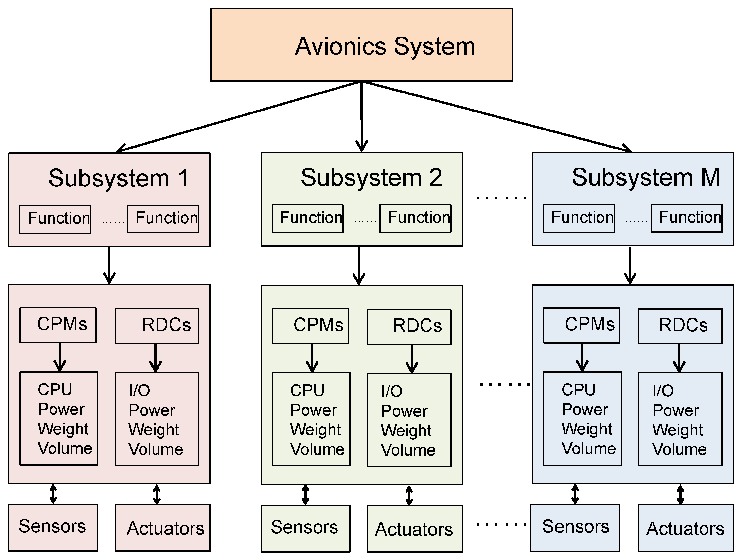
2. Architecture of Dima System

Understanding system architecture of DIMA is essential for optimizing the system. Figure 1 illustrates the overall architecture of DIMA system, with the consideration of the hardware and software mapping and its quality measures as well as constraints. It has a hierarchical layer design for allocation, which includes system layer, hardware layer, and installation layer. The subsystems in the system layer are supported by the hardware in the hardware layer, with functions mapped into devices and signals into links. The hardware in the hardware layer is installed into the installation layer, by placing devices into mount locations and connecting cables via networks.

2.1. System Layer

The system layer describes the functional subsystems. From the perspective of system design, each subsystem has its own specifications, including resource requirements (i.e., computation and storage), connectivity requirements, specific capacity and other properties of relevance for the DIMA architecture design such as their Design Assurance Level (DAL) or specific hardware dependencies. As shown in Figure 2, DIMA system is broken down into a hierarchical tree of subsystems, with the root node representing the entire system [25]. Typical subsystems in the aircraft can be Bleed-Air System (BAS), Overheat Detection System (OHDS), Pneumatic System (PS) and Ventilation Control System (VCS) [26]. The purpose of this layer is to capture the system logic, tasks and connections, as well as peripherals and interfaces for functional subsystems.
Each of the subsystems in the system layer is composed of functions from an architectural point of view. Such an abstraction in form of functions is beneficial to reduce the complexity of the system. Typical functions of the aircraft include but are not limited to: aileron control, multi-function spoilers control, ground spoilers control, rudder control and brake function. For example, an aileron controller function is in charge of monitoring and actuating flight control surfaces. It may consist of a sensor acquisition module, a monitor module, and an actuator controller module. These modules are enabled by a set of hardware components in the hardware layer, including CPMs, RDCs and sensors. More discussions of these hardware components will be given in Section 2.2.

2.2. Hardware Layer

The hardware layer contains hardware devices, their configurations, and network topology, which support the functions in the system layer. The main categories of DIMA devices are sensors, actuators, cables, switches, Core Processing Modules (CPMs), Remote Data Concentrators (RDCs), and Input/Output (I/O). The purpose of these devices is to provide the necessary resources (computing power, memory, data storage, etc.) to the system. Each device is characterized by its type (Central Processing Units (CPUs), network hardware, or peripherals), vendor, weight, volume, power, input ports, output ports and supported signal types. Such characteristics are important in designing the quality measures and constraints in the optimization problem. The details of the DIMA devices are as follows.

2.2.1. Sensor/Actuator

Sensors and actuators are peripherals that sense and control the physical airplane. Sensors perform data acquisition including position, pressure, temperature and other readings. Actuators manipulate various control surfaces and other systems such as cabin pressure or landing gear.

2.2.2. Core Processing Module

CPM provides computation resources and storage for the tasks on the DIMA system. Core Processor Input/Output Module (CPIOM) is a variant that provides a combination of compute resources, input and output ports for distributed data pre-processing or tightly coupled control loops. By using CPIOMs, one may ease the need for high-speed field buses or dedicated I/O communication devices. However, the disadvantage of such I/O integration may come at the increasing number of different CPIOMs required for specific needs [27].

2.2.3. Input/Output

I/O devices allow data conversion and communication to external devices outside the DIMA system, which are not compatible with the internal network. Usually, these are sensors (providing inputs) and actuators (requiring outputs) that interface the DIMA system. The I/O interface can be integrated or separated from CPMs. The integration of application processing and I/O functions is enabled by CPIOM, while their physical separation is enabled by the concept of Distributed Modular Electronics (DME) [27].

2.2.4. Network

Processing components and I/O handling components exchange signals and communicate through Avionics Data Communication Network (ADCN) [28]. ADCN is based on Avionics Full-Duplex Switched Ethernet (AFDX) with a switched star topology [29], which is a standard protocol in DIMA architecture. The central concept of AFDX networks is Virtual Link (VL), which designates the flow of information between functions. A VL is an unidirectional logic path connecting the source to all of the destination end-systems with only switches as intermediate nodes in the path. From a graphical point of view, it consists of paths from the source node to each of the terminal nodes.
Switches and cables are the backbone of AFDX network hosting the communications between CPMs and other devices connected to the network. AFDX messages between functions are realized by connection of cables between devices located in different cabinets.

2.2.5. Remote Data Concentrator

Remote Data Concentrator (RDC) connects sensors and actuators through ADCN with CPMs. RDC is usually placed near sensors and actuators so that fewer cables are needed. It translates signals between different protocols such as Controller Area Network (CAN) and Inter-Integrated Circuit (I2C) of peripherals.

2.3. Installation Layer

The installation layer describes hardware allocation to the anatomy of underlying aircraft. It is powered by mount locations and power network.
Hardware devices can be installed at different mount locations of the aircraft, such as cockpit, avionics bay, middle, tail, and so forth. The installation location is characterized by its coordinates, volume, cooling capacity, power supply, number of slots and mass. The location characteristics should be considered for the optimization on installation of devices. While placement of some components are fixed (e.g. sensors and actuators), CPMs placement and cable routing are needed to determine for the optimization subject to constraints, such as physical and safety requirements.
The power network enables the mount locations to be connected with tunnels, which provides power for the devices installed at the location. Such a network is different from the one in the hardware layer that represents communication network among the devices.
These three layers are interconnected via hardware and software mapping in the DIMA system. Particularly, the hardware and software mapping can include the followings:
  • Device assignment: it maps devices to locations in the aircraft. The assignment should consider connectivity and physical constraints.
  • Task assignment: it maps tasks to devices. The assignment should consider resource and segregation constraints.
  • Link assignment: it maps cable routes for links to connect devices. The assignment should consider connectivity and resource constraints.
  • Signal assignment: it maps signals to links when tasks, devices, and links are assigned. The assignment should consider segregation and resource constraints.
Such hardware and software mapping should be carefully designed by considering a set of quality measures and aircraft constraints, which calls for a formalization of DIMA optimization presented in Section 3.

3. Formalization of Dima Optimization

Hardware and software mapping on different hierarchical layers aims to optimize a set of quality measures for DIMA systems. Meanwhile, the optimization requires to satisfy a group of the constraints due to resource limitation, inherent aircraft architecture and performance requirements [30,31]. Such a DIMA optimization problem is commonly formulated by Integer Linear Program (ILP) [9,32,33,34,35]. In this section, we generalize from the previous works a basic formulation that can be easily extended with additional performance measures under ILP and solved by any multi-objective optimization methods.

3.1. Notation

We introduce notations F , D and L to represent functions, devices and locations in the DIMA system as follows:
  • Functions are denoted as F = { F 1 , , F n } , where n is the number of functions;
  • Communication between functions are defined by virtual links V ;
  • Devices are denoted as D = { D 1 , , D m } , where m is the number of devices;
  • Installation locations are denoted as L = { L 1 , , L l } , where l is the number of locations.
In addition, some sets of binary indicator variables are introduced to represent the utilization of devices, cables and locations as well as the mapping of functions and devices as follows:
  • D indicates the usage of device D D , where D = 1 represents the device is used, and D = 0 otherwise;
  • F , D describes function mapping, where F , D ( F , D ) = 1 represents if function F F is allocated to device D D and F , D ( F , D ) = 0 otherwise;
  • D , D indicates the physical cables between devices, where D , D ( D , D ) = 1 if D and D are connected and D , D ( D , D ) = 0 otherwise;
  • V = { V i j s } denotes whether D i and D j are connected with respect to the virtual link V ( F s ) of function F s .

3.2. Aircraft Constraints

Five categories of constraints should be considered in DIMA optimization:
  • Resource constraints determine the availability of computing resources for mapping functions to devices, for example, CPU, memory and power.
  • Physical constraints enforce physical boundaries of the system for placing devices to locations, such as, weight, volume, the number of slots and cooling capacities.
  • Connectivity constraints describe the connection between functions attached on DIMA devices.
  • Segregation constraints require that two functions cannot be assigned to the same device due to conflict.
  • Performance constraints characterize specifications that a design should satisfy, for example, bandwidth.
Constraints in each category are elaborated as follows.

3.2.1. Resource Constraints

Each function, when assigned to a device, consumes a certain amount of computing resources of the device, such as CPU time and memory. Computing resources of each device are limited in accommodating functions such that resource consumption by functions should not exceed its availability. Suppose that device D D provides computing resource R D C > 0 and function F F consumes computing resource R F C > 0 . Then, we have the following resource constraint for each device,
F F R F C · ( F , D ) R D C , D D .

3.2.2. Physical Constraints

Each device, when installed in a location, consumes a certain amount of power and volume of a location. Physical resources of each location are limited in accommodating devices such that resource consumption by devices should not exceed its availability. Suppose that location L L provides physical resource R L P > 0 and device D D requires physical resource R D P > 0 . Then, we have the following physical constraint for each location,
D D R D P · ( D , L ) R L P , L L .

3.2.3. Connectivity Constraints

Connectivity of virtual links allows the communication between functions attached on devices. Such a connectivity has its own constraint in that the inflow of a device should be equal to the outflow of the device. As such, we need to model the relationship between the inflow and the outflow of each device. Notice that there can be multiple destinations for the outflow. We define a set of auxiliary variables W = { W i j s t } to model the paths between any two functions, where W i j s t = 1 if the following conditions are satisfied:
  • D i and D j are connected with respect to V ( F s ) ;
  • F s and F t are mapped to D i and D j , respectively;
  • F t is one of the destinations of the virtual link V ( F s ) ,that is, F t V ( F s ) .
To connect a source function F s and a destination function F t , we have the following constraints for any pair of functions. First, the outflow of device D i should sum to 1 if F s is mapped to D i , and 0 otherwise, that is,
D j D W i j s t = ( F s , D i ) , D i D , F s F , F t L ( F s ) .
Second, the inflow of device D j should sum to 1 if F t is mapped to D j , and 0 otherwise, that is,
D i D W i j s t = ( F t , D j ) , D j D , F s F , F t L ( F s ) .
In addition, for intermediate node k, the inflow and the outflow of the mapped devices should be equal, that is,
D i D W i , k s t = D j D W k , j s t , D k D , F s F , F t V ( F s ) .
Notice that the connectivity of the virtual links is established using auxiliary variables W instead of V . Hence, additional constraints are needed to enforce the relationship between W and V . Intuitively, W can be regarded as a “transformation” of V onto a single pair of functions. For a pair of devices D i and D j , if W i j s t = 1 for any F s and F t , the corresponding V i j s should be set to 1. In other words, V i j s equals to the disjunction of W i j s t for given D i and D j , that is,
V i , j s = t W i , j s t .
Standard ILP techniques could represent these disjunctive conditions by a set of linear constraints. As our focus of the paper is DIMA optimization, we will pass the tedious details.

3.2.4. Performance Constraints

Performance constraints can include bandwidth constraints and reliability constraints.
For bandwidth constraints, each virtual link requires a minimum bandwidth to guarantee a valid communication. If F s communicates with F t , cables connecting the mapped devices should reserve enough bandwidth. Furthermore, the total reserved bandwidth of a cable should not exceed its capability. This yields the following constraint,
V ( F ) F s F B F s · V i j s B c a b l e · ( D i , D j ) , D i , D j D ,
where B F s denotes the bandwidth requirement of the virtual link sourcing from F s and B c a b l e denotes the bandwidth of the cable.

3.2.5. Segregation Constraints

Segregation requirement has different levels. Some functions F F must not be assigned to the same device and some devices D D must not be installed on the same location owing to aircraft safety. With the introduced indicators, these requirements can be encoded to the following constraints,
F F ( F , D ) 1 , D D ;
D D ( D , L ) 1 , L L .
In addition, there are some sanity constraints that need to be taken care of in the allocation problem. Since binary variables are used to characterize the allocations between optimization identities, constraints should be added to ensure that each function is uniquely mapped to a device, and each device is installed at only one location. Thus, we have the following constraints for each function and device, respectively,
D D ( F , D ) = 1 , F F ;
L L ( D , L ) = ( D ) ,   D D .
The consistency of function-location relationship is further maintained by enforcing
( F , L ) = D D ( F , D ) · ( D , L ) , F F , L L .

3.3. Objectives

The objectives of DIMA optimization can be considered from quality measures in an avionics system, which can be classified into two categories, that is, effectiveness and cost.
Effectiveness refers to the capacity of the system, such as safety, reliability, availability, and scalability. They are summarized as follows:
  • Safety: it can be measured by the number of harmful events during the flight, that is, N h T , where N h is the number of harmful events and T is the number of flight hours.
  • Reliability: it can be modeled as an exponential function of failure rate, that is, R ( t ) = e t r , where r = N f T with N f as the number of failures during the flight and t is the elapsed time.
  • Availability: it can be modeled as the ratio between Mean Time To Failure (MTTF) T f t o ¯ and Mean Time Between Failures (MTBF) T f b e t ¯ , that is, A = T f t o ¯ T f b e t ¯ . MTTF is the averaged elapsed time from normal operation to a failure, which indicates the averaged operation time without failures for system availability. MTBF is the averaged elapsed time between two failures. The gap between MTBF and MTTF is MTTR, which is short for Mean Time To Repair that turns the system back to normal condition from failures. Ideally, we seek to achieve low MTTR and high MTTF for high system availability.
  • Scalability: it can be considered as the percentage of spare resources, that is, R s p a r e R t o t a l , where R s p a r e refers to as the spare resources and R t o t a l refers to as the total resources.
The cost refers to the operating cost and acquisition cost of the system, such as the complexity, weight, power consumption, maintainability and mass from an economic perspective. They are summarized as follows:
  • Complexity: the ratio between the number of DIMA devices m and the number of device types m T , m / m T .
  • Weight: the mass of all the DIMA devices.
  • Operation: the costs for operation include Ship Set Costs (SSC), Operational Interruption Costs (OIC), and Initial Provisioning Costs (IPC). SSC are the recurring costs for installing all the devices and wires onto the avionics system. OIC are the average costs due to flight delays and cancelations for tackling unscheduled maintenance events, which depends on the reliability of avionics devices and the criticality of functions hosted by the devices. IPC are the costs for provisioning spare parts to guarantee an interruption-free operation; it is increased by a higher number of devices or lower MTBF.
  • Power consumption: power consumed by DIMA devices.
  • Maintainability: MTTR is used to measure the maintainability of items that need to be repaired. Long MTTR indicates that it is difficult to perform maintenance.
Particularly, the operational costs, that is, OIC and IPC are affected by MTBF from the performance aspect. The quality measures can be evaluated through a discrete event simulation method [36,37].
As an example, we can consider the mass of devices as follows. The total mass of devices can be written as
D D M D · ( D ) ,
where M D is the mass of device D. The total mass of cables is expressed as
L , L L D , D D ρ · d L , L · ( D , D ) · ( D , L ) · ( D , L ) ,
where d L , L is the distance between locations L and L , and ρ is the mass of the cable per unit length. Note that the objective involves a product term ( D , D ) · ( D , L ) · ( D , L ) . However, since all the variables are binary, standard tricks can be applied so that the term could be transformed into a set of linear constraints. Other metrics, such as the overall SSC and power consumption, can be calculated in the same way as the mass.

3.4. Generic Problem Formulation

A common goal is to minimize the cost and maximize the effectiveness measure simultaneously under certain aircraft constraints. Nevertheless, some of these objectives are conflicting and cannot reach optimality without sacrificing others. If we reduce the mass, then the reliability will decrease, thus increasing the maintenance cost. Therefore, it often requires to determine the best resource allocation strategy for the best possible trade-off among conflicting objectives, which is covered by multi-objective optimization techniques. Mathematically, a generic problem formulation for DIMA optimization can be given as follows,
min x f ( x ) s . t . g ( x ) 0 , h ( x ) = 0 ,
where x = { F , D , L } are decision variables, f is the set of objective functions to be minimized, g and h are the sets of constraints.
DIMA optimization in Equation (15) can be regarded as a general assignment problem (GAP). GAP is very common for modeling distributed systems and applications, such as video placement for social media [38,39], virtual machine placement in data center networks [40], warehouse selection and fleet routing [41], task scheduling in distributed systems [42,43], and resource management in cloud systems [44,45,46]. The assignment problems are usually solved by standard solvers or heuristic algorithms, which can be applied to DIMA optimization.

4. Optimal Mapping In Dima

In this section, we focus on how to solve the optimization problem of DIMA systems. Figure 3 summarizes the approaches for solving DIMA optimization, given DIMA architecture, multiple objectives and aircraft constraints. The majority of existing works provide exact solution and metaheuristic solution to the DIMA optimization problem, while approximate algorithms based on Linear Programming (LP) relaxation or Lagrangian relaxation [47] are not yet adopted. We summarize the previous work on the optimal mapping in DIMA from the perspective of single objective optimization and multi-objective optimization, respectively.

4.1. Solution of Single Objective Optimization

Integer linear programming theory and boolean satisfiability theory can be applied in the DIMA optimization.

4.1.1. Ilp Solvers

ILP can be solved by exact algorithms, approximate algorithms and metaheuristic algorithms. Solutions from exact algorithms guarantee optimality, and meanwhile, the feasibility of the solutions is satisfied. Standard solvers, such as CPLEX and GUROBI, can produce global optimal solutions.
Annighofer et al. in Reference [34] presented binary program formulations and leveraged ILP solver to find the optimal solution for the allocation of modules and resources. Given a set of devices, the placement of the functions onto the devices can be represented as binary variables. In the formulation, two sets of objectives are considered individually, including mass (consisting of peripheral wire mass, device mass and total mass) and operational interruption cost. This leads to a standard ILP formulation with single objective function. Segregation, device locations and power constraints are considered in the optimization problem. The optimizations are implemented in Matlab using CPLEX and exact solutions are given to the optimal hardware and software mapping problems according to the different objective functions.
Al-Sheikh et al. in Reference [48] solved a task mapping and scheduling problem of maximizing the spare time on distributed processing units for IMA architecture, by integer linear program. A set of constraints were considered in the optimization problem, including memory capacity and the maximum number of allocated jobs on each module as well as segregation constraints. ILP was adopted to formulate the optimization problem and optimal solutions were obtained. Similarly, Sivanthi et al. in Reference [28] proposed a task assignment algorithm for avionics system, minimizing total execution time with respect to AFDX delays.
In addition, rather than using standard solvers, some researchers adopt metaheuristic search methods to solve the ILP in DIMA optimization. Although it is usually difficult to determine whether a reported solution is indeed optimal, metaheuristic algorithms can efficiently generate solutions that are “good enough”. Selicean et al. [35] leveraged Tabu search method to minimize the development costs. The optimization problem aims to find the mapping of tasks to processors, the assignment of tasks to partitions, and the scheduling sequence on each processor, while all the applications must meet their deadlines. To avoid obtaining local minima, Tabu search incorporates an adaptive memory to prevent the search from revisiting previous solutions and search the unexplored regions for the solution when there is no improvement in finding a better solution. Zhang et al. [49] minimized the utility function subject to safety requirement with particle swarm optimization. The utility function is defined as the total cost of the system. The constraint is characterized by system failure probability as the sum of failure probabilities of CPMs and RDCs processing resources, which should be below the minimum requirement. Particle swarm optimization [50] based on swarm intelligence is leveraged to solve the optimization problems for finding the mappings among locations, devices and tasks. Each particle moves in a certain velocity in the search space iteratively to search for better positions. The position represents a candidate solution to the optimization problem.

4.1.2. Boolean Satisfiability Theory

Boolean optimization problem, based on boolean satisfiability theory, aims to find a satisfying solution for a given Conjunctive Normal Form (CNF) formula subject to minimizing a given cost function. Constraints can be expressed by means of a propositional boolean formula, which is determined to be satisfiable or not. Typically, SAT-based linear search algorithms and SAT-Based branch and bound algorithms are two common approaches to finding the solution of the optimization problem [51]. A solver for Boolean satisfiability theory is SAT4J [32], which is a mature open-source library in Java. It has been claimed that SAT-based methods are in general faster than generic ILP solvers [52], for example, for the problems of graph coloring and Field Programmable Gate Array (FPGA) routing [53], by capturing the boolean nature of the problem.
Carta et al. [54] leveraged the SAT4J solver to find resource allocation in IMA system to satisfy safety, performance, maintainability and extensibility requirements; the formulation and method can be adapted in the DIMA architecture. Specifically, the authors considered four objective functions individually to be minimized, including unavailability of devices, bandwidth utilization, number of nodes and number of edges, subject to various constraints, such as availability, bandwidth and segregation constraints:
  • Availability optimization: two formulations are considered, that is, 1) to minimize the sum of route unavailability of data flow (referred to as minsum formulation); 2) to minimize the maximum route unavailability (referred to as minmax formulation).
  • Bandwidth utilization optimization: minsum and minmax formulations are considered for the utilization of bandwidth, similar to the availability optimization.
  • Number of nodes optimization: to minimize the sum of binary variables for nodes, where the binary variable is defined as an indicator whether a node is being used by data flow.
  • Number of edges optimization: to minimize the sum of binary variables for edges, where the binary variable is defined as an indicator whether an edge is being used by data flow.
SAT4J based on SAT theory is leveraged to solve the minsum formulation, while lp_solve as a Mixed Integer Linear Programming (MILP) solver is leveraged to solve the minmax formulation. The solutions for the two formulations can be different. Regarding the bandwidth consumption optimization, the minsum formulation for bandwidth consumption optimization may result in unbalanced load, while the minmax formulation can be effective to distribute the load among the network. Its performance evaluation will be discussed with details in Section 5.

4.2. Solution of Multi-Objective Optimization

4.2.1. Weighted Sum

A simple way to solve multi-objective optimization is weighted sum method [55], which sums up multiple objective functions as a single one with different weighting factors [56]; weighted product method [57] and weighted min-max method [58] are similar approaches. Zhang et al. in [49] minimized the objective function of system failure rate, which is the total sum of failure rate functions for measuring the system safety. Via multiple disciplinary optimization, the optimization problem is decomposed to CPM discipline and RDC discipline. Both disciplines are solved by particle swarm optimization (PSO) and exchange subsidiary variables that serve as the initial value for the next loop of the PSO.
However, assigning weights to different objectives can be cumbersome and call for considerable understanding of the underlying context of the problem. Objective functions would have different ranges and it requires the setting of priorities of some objectives to others. It is still not well investigated on how to set the proper weights for DIMA optimization. Pareto optimization and lexicographic optimization, on the other hand, are more widely used in finding the hardware and software mapping for multi-objective optimization.

4.2.2. Pareto Optimization

The key concept of Pareto optimization is Pareto front that reflects the trade-offs among various objectives for finding good solutions. Pareto front is a set of Pareto optimal points on the boundary of the feasible space and none of them is dominated by others. A point, x X , is Pareto optimal if and only if there does not exist another point, x X , such that f ( x ) f ( x ) [59]. Specifically, Pareto sampling calculates a set of solutions to consider the trade-off among different objectives [60]. Annighofer et al. [9,33,61] presented approaches to calculate all solutions of the Pareto front to represent trade-off decisions for linear cost functions in DIMA optimization. The contributions of their works are summarized with details as follows.
Annighofer et al. [33] presented binary program formulations and extended the work [34] by optimizing multiple objectives. Mass, SSC, OIC and IPC are considered as cost functions, which results in a multi-objective optimization problem. The multi-objective optimization is solved by Pareto optimization, with Pareto front calculated. Results identified by Pareto front demonstrate that significant reduction of OIC can be achieved by increasing little mass for hardware mapping; for software mapping, on the other hand, IPC and OIC are less opposing and the objective values are primarily reduced by using less number of devices.
Annighofer et al. [9] also presented binary program formulations for the optimal mapping and allocation of resources in order to minimize mass and OIC, which are two contradicting objectives. Resource consumption and safety constraints (i.e., segregation with restricted installation locations) are considered in the formulation. Unlike in Reference [33], mass and OIC are modeled as linear and quadratic functions. The extension of using quadratic objective functions, however, renders the optimization problem to be more complicated; it seems to be applicable for very small problems. Two approaches were then investigated to tackle the multiple objectives, that is, Pareto front sampling with branch-and-cut and a genetic algorithm. Experimental results show that the genetic algorithm is not competitive to Pareto front sampling. It is also found that around 10% increase of mass can lead to around 50% decrease of OIC for dealing with the tradeoff between the mass the OIC.
Annighofer et al. [61] investigated the network topology optimization in DIMA using ILP formulation, by calculating the best trade-off solutions for multiple objectives. The objectives in the formulation are mass and OIC. Different from References [9,33,34], it considers the switch capacity of the signal and link for the node usage and edge usage for optimally finding ADCN topologies. Algorithms are derived to determine an optimal network topology for switches, switch locations, and interconnections, which reduces the economic cost while respecting bandwidth and safety limitations. Pareto front sampling is used to solve a series of single objective ILPs via the standard solver, for example, CPLEX. In addition, the authors further proposed a variant of the algorithm, which only considers pre-calculated paths for ignoring the paths that are unlikely to be chosen. As the number of variables is reduced, such a heuristic algorithm can reduce execution time for a large-scale system.
Zhou et al. [62] considered a device assignment problem for allocating DIMA devices to installation locations of the aircraft, which is a hardware mapping only. Two objectives were considered for the optimization subject to the resource and safety constraints. A heuristic algorithm, proposed as a two-phase multiobjective local search, was developed to solve the optimization problem efficiently. First, a weighted sum approach was leveraged to approximate a good Pareto front. Second, Pareto local search was conducted on the solutions generated from the first phase to enable further approximation of Pareto front. The alternatives, including Pareto-dominance based algorithm, and local search method combined with decomposition, for example, weighted sum, were compared with the proposed heuristic algorithm. Experimental results showed that the proposed algorithm can scale better than alternatives with the increase of the problem size.

4.2.3. Lexicographic Optimization

Lexicographic optimization [63] is an iterative method to handle multiple objectives. It defines a fixed order of the objectives to be optimized in an iterative manner. A priority is assigned to each objective such that the set of objectives form a lexicographic order. It iteratively optimizes each objective while preserving the optimal values from previous iterations. Hence, an objective with a higher priority explores a larger solution space and makes it closer to its optimal value.
Zhang et al. [64] proposed a physical and function layer modeling for the hardware and software mapping and addressed the DIMA optimization problem using lexicographic optimization. A binary program is presented to formulate the mapping, with the consideration of the slot resource, mass resource, cooling resource and segregation. The objective is to minimize the CPM burden, mass and SSC by optimally finding the installation mapping of the CPMs and RDCs. The CPM burden is defined as resource consumption of all tasks in the CPM device, which reflects the reliability. Besides the conventional measures on the costs and weights of DIMA devices, the reliability is particularly given with higher priority while the cost are given lower priority, including mass, SSC, OIC and IPC. The authors proposed an improved lexicographic optimization to manage the trade-off between the different quality measures. Unlike the traditional lexicographic optimization, the authors applied a relaxed solution space of the preceding optimization. The optimal value of preceding step is relaxed and an offset is added to relax constraints. By using that method, good trade-off between measures can be achieved, while higher priority of reliability is guaranteed. In addition, performance comparison between DIMA and IMA is conducted in the research, showing that DIMA can achieve higher reliability than IMA, while having more SSC and mass for CPMs and RDCs but less SSC and mass for wires. This is due to the distributed architecture of DIMA where all the peripherals are distributively connected to the RDCs.
A list of previous work on DIMA optimization that we have discussed throughout this section are summarized in Table 1 and Table 2. Table 1 summarizes the hardware and software mapping for DIMA optimization from different perspectives of assignment. Furthermore, Table 2 presents the solutions and approaches with more detail. It should be noted that the approximate algorithms are not adopted in the previous work. Most of the work relies on the exact algorithms using standard solvers while there are a few works using metaheuristic or heuristic algorithms that may not be able to guarantee the quality of solutions.

5. Case Studies of Dima Optimization

In this section, we present the case studies of References [33,54] with system configurations and design solutions of hardware and software mapping in DIMA for the single objective optimization and multi-objective optimization, respectively.

5.1. Case Study of Single Objective Optimization

Carta et al. [54] considered a representative aeronautical system, where there are 20 end systems, 73 connections and 4187 signals to be routed. In total, there are 56,088 binary variables in the formulation for optimizing availability (OD), bandwidth (OB), number of nodes (ON), number of edges (OE), subject to constraints of availability (D), bandwidth consumption (B), segregation (S) and virtual link configuration (VL).
The authors measured the processing time of lp_solve and SAT4J PB for solving the optimization problems under a particular objective and certain constraints, in which the experiments were conducted on an Intel Core 2 Duo CPU, 2.93GHz with 8GB RAM. When the number of constraints is smaller and a simpler objective function is considered, for example, in the case of availability optimization (OD), lp_solve is more efficient than SAT4J PB; however, when the number of constraints is larger, for example, in the case of optimizing nodes and edges (ON and OE) with segregation constrain (S), SAT4J PB is much more efficient. For bandwidth optimization (OB), it takes both solvers more processing time, with more than one hour using LP_solve and SAT4J to solve, respectively. As a result, the running time of various objective functions and constraints differs from each other; it depends on what sort of optimization problem is to be solved and what sort of optimization method is to be leveraged.

5.2. Case Study of Multi-Objective Optimization

Annighofer et al. [33] considered a reference architecture of DIMA with 4 aircraft systems of air supply and conditioning domain to be optimized. Apart from allocation of peripherals, 14 DIMA devices, including CPMs and RDCs, are needed to install in 4 locations, that is, BAY, NOSE, MIDDLE, and TAIL. Due to cooling requirement, CPMs are hosted only in the AVIONICS BAY. RDCs can be installed in any of the 4 locations. There are 58 tasks mapped to 14 devices providing 10 resource types subject to 6 segregation constraints. The multi-objective optimization is carried out for software mapping on mass, SSC, IPC and OIC, and hardware mapping on mass and OIC.
The authors proposed a manual reference mapping and three solutions on how devices are installed in the aircraft and tasks are allocated to the devices. The reference mapping does not belong to the Pareto front, but it is designed manually, where all devices are used and cable weight is as low as possible. Compared to the reference mapping, solution 1 is selected from hardware mapping, in which OIC is reduced by moving RDCs with critical tasks to avionics BAY, while cable weight increases slightly. Solution 2, using 9 devices, has the lowest average normalized objective in software mapping. It results in a slightly increasing cable weight, but reduced OIC by avoiding the hardly accessible TAIL installation. Solution 3 is similar to solution 2 except an additional CPM, which offers slightly lower OIC and IPC on the cost of higher mass and SSC. The optimizations were carried out on Windows 7, MATLAB Version 2011b, and CPLEX 12.4 equipped with an Intel Xeon E31270 at 3.4 GHz and 16 GB RAM. Based on the experiments reported, all 1455 solutions of Pareto front could be obtained after 279 min, while the solving time for a single BP run was just around 11.5 s. Consequently, the running time of the multi-objective optimization algorithm is orders of magnitude above that of single objective optimization. Moreover, it increases exponentially with the number of objectives. The running time could be reduced by approximate or heuristic solutions, which can calculate a Pareto front approximation in a single optimization run.

6. Open Issues and Future Trends

In this section, we discuss the open issues and future trends of DIMA.

6.1. System Scalability of Dima Optimization

As the ILP problem itself is NP-hard, the standard solvers for optimal solution will suffer from low computational efficiency in solving optimization problems of a large size. Although it may be efficient for simple problems, it becomes infeasible when the number of constraints and decision variables are large. In DIMA optimization, the number of variables can increase significantly with the number of devices, switches, functions and signals. Such a system setting renders DIMA optimization to be a large-scale mapping problem [65]. Thus, it is still an open issue on how to tackle the scalability of solving the large scale optimization problem in DIMA for achieving the solution close to the optimum within an acceptable time.
To extend the scalability of DIMA optimization, we can rely on the following approaches. First, Lagrangian relaxation method can be adopted to obtain the approximate solution for DIMA optimization that is close to the optimum. The Lagrangian relaxation method is a common technique to solve the ILP problem efficiently, which has been experienced on network engineering [38,39,66,67]. The purpose of the relaxation is trying to decompose the original optimization problem into a set of subproblems. By decomposition, each of the subproblems will have much less number of integer variables and constraints, which is easier to solve. For each of the subproblems, subgradient optimization scheme can be used to update the multipliers for obtaining the feasible solution. Second, we can try to restrict the search space and reduce the number of objectives to have an optimization problem of smaller size. For example, in Reference [68], the authors reduced the search space and proposed a heuristic algorithm inspired from game theory for ILP problem. In Reference [65], the authors leveraged backtracking approach to obtain better solutions from a search tree to avoid finding similar solutions. In addition, Ozlen et al. in Reference [69] proposed to leverage the set of subproblems that have been solved to avoid solving a large number of integer programs, thus improving lexicographic optimization. By taking these approaches, the solutions could be provided in an acceptable execution time given a full scale optimization problem.

6.2. Robustness of Dima Optimization

The robustness of DIMA optimization should be considered with the presence of uncertainty, physical variance and external disturbances. The worst case scenario, for example possible failures of some components, must be considered. The authors in [70] explored to provide Worst Case Execution Time (WCET) analysis for the application scheduling in IMA. Further, the authors in [71] presented tight probabilistic WCET estimates using Probabilistic Timing Analysis, which enables system utilization to be optimized. However, such a solution for DIMA is still not available.
Moreover, sensitivity analysis for the ILP formulation is absent in the current research of DIMA optimization, which should also be the future goal for the software and hardware mapping. If solutions are quite sensitive to the variable perturbations, we are more interested in finding the robust solutions. In this case, we can apply robust optimization procedures to solve the DIMA multi-objective optimization problems [72].

6.3. Cyber-Physical Integration Towards Intelligence

Future aircraft under DIMA architecture will increasingly rely on advancements of network and information technologies [73]. The available sensors, data concentrators and actuators establish a connection between the physical world and the cyber network. Specifically, the cyber-physical design and integration will give support for the physical world, such as monitoring of concurrent events, asset health monitoring and prognostics [74], which suggests data-driven approaches for modeling the quality measures of the aircraft, for example, reliability and maintainability, for understanding the dynamic interactions between different components in the DIMA architecture from a statistical view [75]. Powerful machine learning techniques can be leveraged to build the models and learn the association of components for predicting the failure rate and MTTR accurately [76], particularly with deep learning [77]. In this case, rather than traditional physical equations, quality measures can be modeled by machine learning techniques, where training data can come from either discrete event simulations or real world scenarios. Potentially, the modeling of the quality measures can be more accurate and hence the solution of the DIMA optimization will be more reliable.

6.4. Involvement of Cloud Computing

Cloud computing technology, due to its sharing and flexible reconfiguration of resources, can be leveraged into avionics systems [7,78]. The implementation of the so called avionics cloud [78] via virtual machine (VM) management can have the following advantages. First, it can virtualize the avionics resources with arbitrary configuration to improve the resource utilization among different subsystems. Computing and networking resources can be dynamically allocated and deallocated. Second, by virtualization technology, the system can host critical and non-critical functions in a more robust manner. The virtualization technology guarantees that critical functions can achieve the desired Quality of Service (QoS) for execution without being affected by other hosted distributed functions [7]. Functions can be queued to be performed under the cloud-based management. As a result, cloud computing is becoming an approach to designing critical systems with integration of other non-critical functions [79].
Under avionics cloud, as the computing power, memory and storage can be virtualized, we need to consider the mapping between VMs and hardware components. In this case, together with the hardware and software mapping, there will be three levels of mapping when designing the DIMA systems. As such, this will make the function mapping more complicated for both objective functions and constraints. The same optimization framework can still be adopted, but the system complexity will increase with more constraints and variables in the DIMA optimization. It will take more time to find the solution using conventional methods. Distributed optimization using cloud resources has the potential to improve the efficiency and solve this issue [80]. Therefore, such a consideration is important for avionics cloud in future design.

7. Summary

This survey paper investigated the existing literature on hardware and software mapping optimization in DIMA systems. We presented the DIMA architecture with a three-layer design and provided a mathematical representation of constraints and quality measures for this architecture. We then provided a comprehensive discussion on the approaches to optimal resource allocation that are relevant to this domain. More advanced algorithms are expected to design and implement with the increasing size of the optimization problem. We envision that scalability and robustness analysis, cyber-physical integration and cloud-enabled DIMA are future research trends of DIMA optimization.

Author Contributions

Conceptualization, W.Z. and R.S.F.; methodology, W.Z. and R.S.F.; formal analysis, W.Z. and J.L. and L.C.; writing—original draft preparation, W.Z.; writing—review and editing, J.L. and R.S.F. and F.G.; funding acquisition, J.L. and L.C. All authors have read and agreed to the published version of the manuscript.

Funding

This work is supported by National Natural Science Foundations of China (No. 61701122), Top Youth Talent Project of Zhujiang Talent Program (No. 2019QN01X516), Guangdong Basic and Applied Basic Research Foundation (No. 2019A1515011056), NSFC-Guangdong Joint Fund (Nos. U1701262, U1801263), Guangdong Provincial Key Laboratory of Cyber Physical System (No. 2016B030301008) and National Science and Technology Planning Project (No.2019YFB1705503).

Conflicts of Interest

The authors declare no conflict of interest.

References

  1. FAA. Aviation Maintenance Technician Handbook-Airframe; United States Department of Transportation, Federal Aviation Administration, Airman Testing Standards Branch: Washington, DC, USA, 2012; Chapter 11; Volume 2.
  2. Moir, I.; Seabridge, A. Aircraft Systems: Mechanical, Electrical, and Avionics Subsystems Integration, 3rd ed.; Aerospace Series; John Wiley & Sons, Ltd.: Hoboken, NJ, USA, 2008. [Google Scholar]
  3. Bieber, P.; Boniol, F.; Boyer, M.; Noulard, E.; Pagetti, C. New Challenges for Future Avionic Architectures. AerospaceLab 2012, 4, 1–10. [Google Scholar]
  4. Butz, H. Open integrated modular avionics (IMA): State of the art and future development road map at Airbus Deutschland. Signal 2010, 10, 1000. [Google Scholar]
  5. Moir, I.; Seabridge, A.; Jukes, M. Civil Avionics Systems, 2nd ed.; Aerospace Series; John Wiley & Sons, Ltd.: Hoboken, NJ, USA, 2013. [Google Scholar]
  6. Gaska, T.; Watkin, C.; Chen, Y. Integrated Modular Avionics-Past, present, and future. IEEE Aerosp. Electron. Syst. Mag. 2015, 30, 12–23. [Google Scholar] [CrossRef]
  7. Jakovljevic, M.; Ademaj, A. Distributed IMA: Use cases for embedded platforms. In Proceedings of the 2015 34th IEEE/AIAA Digital Avionics Systems Conference (DASC), Prague, Czech Republic, 13–17 September 2015. [Google Scholar]
  8. Batista, L.; Hammami, O. Capella based system engineering modelling and multi-objective optimization of avionics systems. In Proceedings of the 2016 IEEE International Symposium on Systems Engineering, Edinburgh, UK, 3–5 October 2016; pp. 1–8. [Google Scholar]
  9. Annighöfer, B.; Kleemann, E.; Thielecke, F. Automated selection, sizing, and mapping of integrated modular avionics modules. In Proceedings of the 2013 32nd IEEE/AIAA Digital Avionics Systems Conference (DASC), East Syracuse, NY, USA, 5–10 October 2013. [Google Scholar]
  10. Halle, M.; Thielecke, F. Next generation IMA configuration engineering - from architecture to application. In Proceedings of the 2015 34th IEEE/AIAA Digital Avionics Systems Conference (DASC), Prague, Czech Republic, 13–17 September 2015. [Google Scholar]
  11. Zhou, Q.; Xiong, Z.; Zhan, Z.; You, T.; Jiang, N. The mapping mechanism between Distributed Integrated Modular Avionics and data distribution service. In Proceedings of the 2015 12th International Conference on Fuzzy Systems and Knowledge Discovery, Zhangjiajie, China, 15–17 August 2015; pp. 2502–2507. [Google Scholar]
  12. Sheng, W.; Yu, J.; Weng, Z.; Tang, D. A distributed and reusable workflow-based auto test framework for distributed integrated modular avionics. In Proceedings of the 2017 IEEE AUTOTESTCON, Schaumburg, IL, USA, 9–15 September 2017. [Google Scholar]
  13. Han, P.; Zhai, Z.; Nielsen, B.; Nyman, U. A Modeling Framework for Schedulability Analysis of Distributed Avionics Systems. In Proceedings of the 3rd Workshop on Models for Formal Analysis of Real Systems and 6th International Workshop on Verification and Program Transformation, MARS/VPT@ETAPS 2018, Thessaloniki, Greece, 20 April 2018; pp. 150–168. [Google Scholar]
  14. Han, P.; Zhai, Z.; Nielsen, B.; Nyman, U. A Compositional Approach for Schedulability Analysis of Distributed Avionics Systems. In Proceedings of the 1st International Workshop on Methods and Tools for Rigorous System Design, MeTRiD@ETAPS 2018, Thessaloniki, Greece, 15 April 2018; pp. 39–51. [Google Scholar]
  15. Deroche, E.; Scharbarg, J.L.; Fraboul, C. Mapping real-time communicating tasks on a distributed IMA architecture. In Proceedings of the 2016 IEEE 21st International Conference on Emerging Technologies and Factory Automation, Berlin, Germany, 6–9 September 2016. [Google Scholar]
  16. Deroche, E.; Scharbarg, J.L.; Fraboul, C. A greedy heuristic for distributing hard real-time applications on an IMA architecture. In Proceedings of the 2017 12th IEEE International Symposium on Industrial Embedded Systems, Toulouse, France, 14–16 June 2017. [Google Scholar]
  17. Salomon, U.; Reichel, R. Automatic design of IMA systems. In Proceedings of the 2013 IEEE Aerospace Conference, Big Sky, MT, USA, 2–9 March 2013. [Google Scholar]
  18. CPLEX. Available online: https://www.ibm.com/software/commerce/optimization/cplex-optimizer/ (accessed on 11 April 2020).
  19. GUROBI. Available online: http://www.gurobi.com/ (accessed on 11 April 2020).
  20. Neji, N.; De Lacerda, R.; Azoulay, A.; Letertre, T.; Outtier, O. Survey on the future aeronautical communication system and its development for continental communications. IEEE Trans. Veh. Technol. 2013, 62, 182–191. [Google Scholar] [CrossRef] [Green Version]
  21. Gui-rong, X.H.G.Z.; Qiao, L. A survey on avionics bus and network interconnections and their progress. Acta Aeronaut. Et Astronaut. Sin. 2006, 6, 1135–1144. [Google Scholar]
  22. Yong-fei, D. Survey of Airborne Avionics Bus System Progress. Avion. Technol. 2003, 2, 1–7. [Google Scholar]
  23. Liu, L.; Ma, A.; Liu, H.; Feng, X.; Shi, M.; Dong, R.; Zhao, Y. Research progress of engineering structural optimization in aerospace field. In Proceedings of the 2016 7th International Conference on Mechanical and Aerospace Engineering (ICMAE), London, UK, 18–20 July 2016; pp. 558–562. [Google Scholar]
  24. Wang, H.; Niu, W. A Review on Key Technologies of the Distributed Integrated Modular Avionics System. Int. J. Wirel. Inf. Netw. 2018, 25, 358–369. [Google Scholar] [CrossRef]
  25. Wang, T.; Qingfan, G. Research on distributed integrated modular avionics system architecture design and implementation. In Proceedings of the 2013 32nd IEEE/AIAA Digital Avionics Systems Conference (DASC), East Syracuse, NY, USA, 5–10 October 2013. [Google Scholar]
  26. Annighöfer, B.; Thielecke, F. A systems architecting framework for optimal distributed integrated modular avionics architectures. CEAS Aeronaut. J. 2015, 6, 485–496. [Google Scholar] [CrossRef]
  27. Fuchsen, R. Preparing the next generation of IMA: A new technology for the scarlett program. In Proceedings of the 2009 28th IEEE/AIAA Digital Avionics Systems Conference (DASC), Orlando, FL, USA, 23–29 October 2009. [Google Scholar]
  28. Sivanthi, T.; Zhang, S.; Killat, U. A holistic framework for optimal avionics system resource planning. In Proceedings of the 2007 Workshop on Aicraft System Technologies, Hamburg, Germany, 29–30 March 2007; pp. 257–268. [Google Scholar]
  29. Itier, J.B. A380 integrated modular avionics. In Proceedings of the ARTIST2 Meeting on Integrated Modular Avionics, Roma, Italy, 12–13 November 2007; Volume 1, pp. 72–75. [Google Scholar]
  30. Bieber, P.; Bodeveix, J.P.; Castel, C.; Doose, D.; Filali, M.; Minot, F.; Pralet, C. Constraint-based design of avionics platform-preliminary design exploration. In Proceedings of the 4th European Congress ERTS Embedded Real Time Software, Toulouse, France, 29 January–1 February 2008. [Google Scholar]
  31. Sagaspe, L.; Bieber, P. Constraint-based design and allocation of shared avionics resources. In Proceedings of the 2007 26th IEEE/AIAA Digital Avionics Systems Conference (DASC), Dallas, TX, USA, 21–25 October 2007. [Google Scholar]
  32. Le Berre, D.; Parrain, A. The Sat4j library, release 2.2, system description. J. Satisf. Boolean Model. Comput. 2010, 7, 59–64. [Google Scholar]
  33. Annighöfer, B.; Thielecke, F. Multi-objective mapping optimization for distributed Integrated Modular Avionics. In Proceedings of the 2012 31st IEEE/AIAA Digital Avionics Systems Conference (DASC), Williamsburg, VA, USA, 14–18 October 2012. [Google Scholar]
  34. Annighöfer, B.; Thielecke, F. Supporting the Design of Distributed Integrated Modular Avionics Systems with Binary Programming; Deutscher Luft-und Raumfahrtkongress: Bonn, Germany, 2012. [Google Scholar]
  35. Selicean, D.T.; Pop, P. Design optimization of mixed-criticality real-time applications on cost-constrained partitioned architectures. In Proceedings of the 2011 IEEE 32nd Real-Time Systems Symposium (RTSS), Vienna, Austria, 29 November–2 December 2011; pp. 24–33. [Google Scholar]
  36. Li, X.; Xiong, H. Modelling and simulation of integrated modular avionics systems. In Proceedings of the 2009 28th IEEE/AIAA Digital Avionics Systems Conference (DASC), Orlando, FL, USA, 23–29 October 2009. [Google Scholar]
  37. Liu, X.; Cao, C.; Zhao, X.; Sun, J.; Zhu, J. Network performance analysis of Time-Triggered Ethernet based on network calculus for DIMA. In Proceedings of the 2015 34th IEEE/AIAA Digital Avionics Systems Conference (DASC), Prague, Czech Republic, 13–17 September 2015. [Google Scholar]
  38. Bektaş, T.; Oğuz, O.; Ouveysi, I. A Lagrangean relaxation and decomposition algorithm for the video placement and routing problem. Eur. J. Oper. Res. 2007, 182, 455–465. [Google Scholar] [CrossRef] [Green Version]
  39. Wu, Y.; Wu, C.; Li, B.; Zhang, L.; Li, Z.; Lau, F. Scaling social media applications into geo-distributed clouds. In Proceedings of the 2012 IEEE INFOCOM Proceedings, Orlando, FL, USA, 25–30 March 2012; pp. 684–692. [Google Scholar]
  40. Kanagavelu, R.; Lee, B.S.; Le, N.T.D.; Mingjie, L.N.; Aung, K.M.M. Virtual machine placement with two-path traffic routing for reduced congestion in data center networks. Comput. Commun. 2014, 53, 1–12. [Google Scholar] [CrossRef]
  41. Han, Y.; Guan, X.; Shi, L. Optimization based method for supply location selection and routing in large-scale emergency material delivery. IEEE Trans. Autom. Sci. Eng. 2011, 8, 683–693. [Google Scholar] [CrossRef] [Green Version]
  42. Topcuoglu, H.; Hariri, S.; Wu, M.Y. Performance-effective and low-complexity task scheduling for heterogeneous computing. IEEE Trans. Parallel Distrib. Syst. 2002, 13, 260–274. [Google Scholar] [CrossRef] [Green Version]
  43. Yu, J.; Buyya, R.; Tham, C.K. Cost-based scheduling of scientific workflow applications on utility grids. In Proceedings of the First International Conference on e-Science and Grid Computing (e-Science’05), Melbourne, Vic., Australia, 5–8 July 2005. [Google Scholar]
  44. Gao, G.; Wen, Y.; Zhang, W.; Hu, H. Cost-efficient and QoS-aware content management in media cloud: Implementation and evaluation. In Proceedings of the 2015 IEEE International Conference on Communications (ICC), London, UK, 8–12 June 2015; pp. 6880–6886. [Google Scholar]
  45. Zhang, W.; Wen, Y. Energy-efficient task execution for application as a general topology in mobile cloud computing. IEEE Trans. Cloud Comput. 2018, 6, 708–719. [Google Scholar] [CrossRef]
  46. Zhang, W.; Wen, Y.; Wong, Y.W.; Toh, K.C.; Chen, C.H. Towards joint optimization over ict and cooling systems in data centre: A survey. IEEE Commun. Surv. Tutor. 2016, 18, 1596–1616. [Google Scholar] [CrossRef] [Green Version]
  47. Geoffrion, A.M. Lagrangean Relaxation for Integer Programming; Springer: Berlin, Germany, 1974. [Google Scholar]
  48. Al-Sheikh, A.; Brun, O.; Hladik, P.E. Decision support for task mapping on IMA architecture. In Proceedings of the 3rd Junior Researcher Workshop on Real-Time Computing (JRWRTC2009), Paris, France, 26–27 October 2009; pp. 31–34. [Google Scholar]
  49. Zhang, C.; Shi, X.; Chen, D. Safety analysis and optimization for networked avionics system. In Proceedings of the 33rd IEEE/AIAA Digital Avionics Systems Conference (DASC), Colorado Springs, CO, USA, 5–9 October 2014. [Google Scholar]
  50. Kennedy, J. Particle swarm optimization. In Encyclopedia of Machine Learning; Springer: Berlin, Germany, 2011; pp. 760–766. [Google Scholar]
  51. Manquinho, V.M.; Silva, J.P.M. On Solving Boolean Optimization with Satisfiability-Based Algorithms. In Proceedings of the 6th International Symposium on Artificial Intelligence and Mathematics (AIAM), Fort Lauderdale, FL, USA, 5–7 January, 2000. [Google Scholar]
  52. Aloul, F.A. On Solving Optimization Problems Using Boolean Satisfiability. In Proceedings of the International Conference on Modeling, Simulation, and Applied Optimization (ICMSAO), Marrakesh, Morocco, 24–27 March 2005. [Google Scholar]
  53. Aloul, F.A.; Sakallah, K.A.; Markov, I.L. Efficient symmetry breaking for boolean satisfiability. IEEE Trans. Comput. 2006, 55, 549–558. [Google Scholar] [CrossRef]
  54. Carta, D.C.; de Oliveira, J.M.P.; Starr, R.R. Allocation of avionics communication using Boolean satisfiability. In Proceedings of the 2012 31st IEEE/AIAA Digital Avionics Systems Conference (DASC), Williamsburg, VA, USA, 14–18 October 2012. [Google Scholar]
  55. Marler, R.T.; Arora, J.S. The weighted sum method for multi-objective optimization: New insights. Struct. Multidiscip. Optim. 2010, 41, 853–862. [Google Scholar] [CrossRef]
  56. Hwang, C.L.; Masud, A.S.M. Multiple Objective Decision Making—Methods and Applications: A State-of-the-Art Survey; Springer Science & Business Media: Berlin, Germany, 2012; Volume 164. [Google Scholar]
  57. Zavadskas, E.; Turskis, Z.; Antucheviciene, J.; Zakarevicius, A. Optimization of weighted aggregated sum product assessment. Elektron. Ir Elektrotechnika 2012, 122, 3–6. [Google Scholar] [CrossRef]
  58. Sayın, S.; Kouvelis, P. The multiobjective discrete optimization problem: A weighted min-max two-stage optimization approach and a bicriteria algorithm. Manag. Sci. 2005, 51, 1572–1581. [Google Scholar] [CrossRef]
  59. Marler, R.T.; Arora, J.S. Survey of multi-objective optimization methods for engineering. Struct. Multidiscip. Optim. 2004, 26, 369–395. [Google Scholar] [CrossRef]
  60. Mueller-Gritschneder, D.; Graeb, H.; Schlichtmann, U. A successive approach to compute the bounded Pareto front of practical multiobjective optimization problems. SIAM J. Optim. 2009, 20, 915–934. [Google Scholar] [CrossRef]
  61. Annighoefer, B.; Reif, C.; Thieleck, F. Network topology optimization for distributed integrated modular avionics. In Proceedings of the 2014 33rd IEEE/AIAA Digital Avionics Systems Conference (DASC), Colorado Springs, CO, USA, 5–9 October 2014. [Google Scholar]
  62. Zhou, Q.; Wang, J.; Zhang, G.; Guo, K.; Cai, X.C.; Wang, L.; Huang, Y. A Two-Phase Multiobjective Local Search for the Device Allocation in the Distributed Integrated Modular Avionics. IEEE Access 2019, 8, 1–10. [Google Scholar] [CrossRef]
  63. Rentmeesters, M.J.; Tsai, W.K.; Lin, K.J. A theory of lexicographic multi-criteria optimization. In Proceedings of the 1996 Second IEEE International Conference on Engineering of Complex Computer Systems, Montreal, QC, Canada, 21–25 October 1996; pp. 76–79. [Google Scholar]
  64. Zhang, C.; Xiao, J. Modeling and Optimization in Distributed Integrated Modular Avionics. In Proceedings of the 2013 32nd IEEE/AIAA Digital Avionics Systems Conference (DASC), East Syracuse, NY, USA, 5–10 October 2013. [Google Scholar]
  65. Hilbrich, R.; Behrisch, M. Experiences gained from modeling and solving large mapping problems during system design. In Proceedings of the 2017 Annual IEEE International Systems Conference (SysCon), Montreal, QC, Canada, 24–27 April 2017; pp. 1–8. [Google Scholar]
  66. He, J.; Bresler, M.; Chiang, M.; Rexford, J. Towards robust multi-layer traffic engineering: Optimization of congestion control and routing. J. Sel. Areas Commun. 2007, 25, 868–880. [Google Scholar] [CrossRef] [Green Version]
  67. Jiang, J.W.; Lan, T.; Ha, S.; Chen, M.; Chiang, M. Joint VM placement and routing for data center traffic engineering. In Proceedings of the INFOCOM Proceedings, Orlando, FL, USA, 25–30 March 2012; pp. 2876–2880. [Google Scholar]
  68. Al Sheikh, A.; Brun, O.; Hladik, P.E.; Prabhu, B.J. Strictly periodic scheduling in IMA-based architectures. Real-Time Syst. 2012, 48, 359–386. [Google Scholar] [CrossRef]
  69. Ozlen, M.; Burton, B.A.; MacRae, C.A. Multi-objective integer programming: An improved recursive algorithm. J. Optim. Theory Appl. 2014, 160, 470–482. [Google Scholar] [CrossRef] [Green Version]
  70. Bradford, R.; Fliginger, S.; Collins, R.; Rapids, I.C.; Nam, M.Y.; Mohan, S.; Pellizzoni, R.; Kim, C.; Caccamo, M.; Sha, L. Exploring the design space of IMA system architectures. In Proceedings of the 2010 29th IEEE/AIAA Digital Avionics Systems Conference (DASC), Salt Lake City, UT, USA, 3–7 October 2010. [Google Scholar]
  71. Wartel, F.; Kosmidis, L.; Lo, C.; Triquet, B.; Quinones, E.; Abella, J.; Gogonel, A.; Baldovin, A.; Mezzetti, E.; Cucu, L.; et al. Measurement-based probabilistic timing analysis: Lessons from an integrated-modular avionics case study. In Proceedings of the 2013 8th IEEE International Symposium on Industrial Embedded Systems (SIES), Graz, Austria, 6–8 June 2013; pp. 241–248. [Google Scholar]
  72. Deb, K.; Gupta, H. Introducing robustness in multi-objective optimization. Evol. Comput. 2006, 14, 463–494. [Google Scholar] [CrossRef]
  73. Sampigethaya, K.; Poovendran, R. Cyber-physical integration in future aviation information systems. In Proceedings of the 2012 31st IEEE/AIAA Digital Avionics Systems Conference (DASC), Williamsburg, VA, USA, 14–18 October 2012. [Google Scholar]
  74. Skormin, V.A.; Gorodetski, V.I.; Popyack, L.J. Data mining technology for failure prognostic of avionics. IEEE Trans. Aerosp. Electron. Syst. 2002, 38, 388–403. [Google Scholar] [CrossRef]
  75. Ezhilarasu, C.M.; Skaf, Z.; Jennions, I.K. The application of reasoning to aerospace Integrated Vehicle Health Management (IVHM): Challenges and opportunities. Progress Aerosp. Sci. 2019, 105, 60–73. [Google Scholar] [CrossRef]
  76. Januzaj, V. Data mining meets system modelling. In Proceedings of the 21st ACM/IEEE International Conference on Model Driven Engineering Languages and Systems: Companion Proceedings, Heraklion, Crete, Greece, 4–5 May 2018; pp. 55–56. [Google Scholar]
  77. LeCun, Y.; Bengio, Y.; Hinton, G. Deep learning. Nature 2015, 521, 436–444. [Google Scholar] [CrossRef]
  78. Li, Z.; Li, Q.; Xiong, H. Avionics clouds: A generic scheme for future avionics systems. In Proceedings of the 2012 31st IEEE/AIAA Digital Avionics Systems Conference (DASC), Williamsburg, VA, USA, 14–18 October 2012. [Google Scholar]
  79. Jakovljevic, M.; Insaurralde, C.C.; Ademaj, A. Embedded cloud computing for critical systems. In Proceedings of the 2014 33rd IEEE/AIAA Digital Avionics Systems Conference (DASC), Colorado Springs, CO, USA, 5–9 October 2014. [Google Scholar]
  80. Wang, Y.; Wang, S.; Wu, L. Distributed optimization approaches for emerging power systems operation: A review. Electr. Power Syst. Res. 2017, 144, 127–135. [Google Scholar] [CrossRef]
Figure 1. System architecture of DIMA. The design of system layer, hardware layer and installation layer is linked with a group of constraints and quality measures.
Applsci 10 02675 g001
Figure 2. The structure of system layer in DIMA. The system layer contains multiple subsystems [25].
Applsci 10 02675 g002
Figure 3. DIMA optimization: mathematical programming framework with incorporation of functional layers profile, system objectives and constraints.
Applsci 10 02675 g003
Table 1. DIMA optimization under different mappings.
ReferenceTask AssignmentDevice AssignmentLink AssignmentSignal Assignment
[34]
[48]
[28]
[35]
[49]
[54]
[33]
[9]
[61]
[62]
[64]
Table 2. A list of previous work on Distributed Integrated Modular Avionics (DIMA) optimization is summarized based on their objectives, constraints, solution and contribution.
PaperObjectiveConstraintsSolutionContribution
[34]Minimize mass and OIC individuallySegregation, device location, power constraintsCPLEXPresent binary program formulation of single objective optimization for DIMA as early work
[48]Maximize spare time of processorsMemory capacity, maximum number of allocated tasks, segregation constraintsILP solverSolve task mapping and scheduling problem for IMA architecture
[28]Minimize execution time of functionsAFDX delayILP solverPropose an algorithm for task assignment with respect to AFDX delay
[35]Minimize development costSegregationTabu search-based algorithmPropose a metaheuristic algorithm for single objective optimization on cost
[49]Minimize the total cost of the systemDevice resourceParticle swarm optimizationPropose a metaheuristic algorithm for single objective optimization on effectiveness
[54]Minimize the maximum bandwidth utilization; maximize the route availability; minimize the number of nodes; minimize the number of edgesSegregation, resource availability, bandwidth consumptionSAT4J solverCompare performance between SAT4J and lp_solve
[49]Minimize the failure probability of CPMs and RDCsDevice resourceWeighted sum method and particle swarm optimizationPropose to use weighted sum method and decompose the problem into CPM discipline and RDC discipline for multi-objective optimization
[33]Minimize mass, SSC, OIC and IPCSegregation, slot resource, cooling capacityCPLEX & Pareto optimizationPresent solution to multi-objective optimization for DIMA as early work
[9]Minimize mass and OICDevice resource and  segregationCPLEX & GUROBIConsider quadratic cost functions for objectives
[61]Minimize mass and OICSegregation, switch capacity (signal and link)CPLEX & GUROBI & Pareto optimizationProvide solution to network topology optimization with multiple objectives
[62]Minimize mass and SSCDevice resource and segregationTwo-phase multiobjective local searchPropose a two-stage approach to solving the multi-objective optimization
[64]Minimize the CPM burden, mass and SSCSlot resource, mass resource, cooling resource and segregationLexicographic optimizationCompare the performance between DIMA and IMA optimization with multiple objectives

