Abstract
Improving the accuracy of the digital model is essential for the digitalization of the dental field. This study introduced a novel method of objective accuracy evaluation of digitized full dental arch model using coordinate measuring machine (CMM). To obtain a true linear measurement value using the CMM, 17 reference balls were attached to the typodont, and 12 measurements between balls on the X-(width), Y-(length), and Z-axes (height) were performed automatically. A rubber impression and a plaster cast replica of the typodont with balls were fabricated, and they were digitized with following methods: (a) true model intraoral scans; (b) impression cone-beam computed tomography (CBCT) scans; (c) cast CBCT scans; and (d) cast extraoral scans. Each scanning method was performed 20 times. Twelve linear measurements on the digitized models were automatically made using software. The one-sample t-test and one-way analysis of variance were used for measurement accuracy analysis. The cast extraoral scan was most accurate on X- and Y-axes, while impression CBCT was the most accurate on Z-axis. Over all axes, the intraoral scan resulted in the most deviation from the true model, and the reproducibility of each scan was also low. Extraoral scan shows high precision on width and length, and impression CBCT is advantageous for dental work where height factor is of importance.
1. Introduction
Digitalization is a recent trend in dentistry, characterized by the development of digital models to replace plaster casts. Many researchers have attempted to minimize the need for conventional laboratory work by enhancing the accuracy of digital models. Thus, numerous previous studies attempted to assess the accuracy of digital models produced in various ways. However, the accuracy evaluation of digital models is challenging when compared to the actual dental arch. In previous studies, researchers set the dental cast model or the extraoral optical-scanner-generated digital model as a gold standard to which they compare digital models obtained with different methods to evaluate the accuracy [1,2,3,4]. This is because there is no proper landmark for measuring true values in the oral cavity, and there is no suitable method to specify the same landmark point on a replicated digital model [5].
For the full dental arch, extraoral desktop scanning of plaster models is a clinically applicable method with acceptable stability and accuracy [6]. An intraoral scanner is advantageous in that it directly scans a patient’s dental arch with no lab work involved, yet the problem of distortion in scans of the full dental arch has not been solved [7]. Moreover, for both extraoral and intraoral optical scanners, light sources have difficulty reaching areas such as proximal undercuts or complex-angled surfaces, meaning that some areas can lack information [8]. These methods generate a digital model through additional data processing steps, and the errors encountered during this process affect the accuracy of the final stereolithography (STL) data [9].
Another emerging method is the use of cone-beam computed tomography (CBCT) to obtain a digitized model by scanning an impression or plaster model in a special image acquisition mode [10]. This method is advantageous in that an additional machine is not required for digital model generation, the scanning time is relatively short, the patient experiences no discomfort, and the characteristics of the X-ray penetrance prevent information loss regardless of the shape of objects such as undercut, in contrast to direct optical scans of the patient’s mouth [11,12,13]. Digital Imaging and Communications in Medicine (DICOM) data that are obtained from CBCT devices can also be converted into STL data using various software [14,15,16]. Thus, the performance of the conversion software also affects the accuracy of the digital models.
As various methods of obtaining digitized models have been developed, many researchers have investigated whether various scanning methods are sufficiently accurate. As stated above, there are several obstacles in assessing the accuracy. First, acquiring precise and reproducible measurements of reference models and digitized models is a challenging process. The common reference points for the measurements are cusp or fossa of the crown, which could be differently pointed on each experiment with low intra- and interobserver reliability [5,17,18,19]. Setting the appropriate reference points is the first step in obtaining reliable data for comparison of accuracy. Second, most studies have primarily involved comparative analyses of digitized data and conventional plaster models or data obtained with optical scanners [1,2,8,20]. Since the digital model generation procedure is based on an impression or plaster model, which already involves distortion, the accuracy of the overall digital model should be evaluated based on the gold standard value obtained from the patient’s actual dental arch.
To obtain this gold standard value with high accuracy, coordinate measuring machines (CMMs) have been introduced in dentistry [21]. CMMs are widely used in industrial applications and are known to be precise and able to be used in the dental field, which requires micro-unit accuracy. This machine contacts the desired point with a probe and records its coordinates. They recognize the shape of the object and measure dimensional length with high accuracy [6].When a CMM is used with a reliable reference point, the gold standard value can be obtained for accuracy assessment of a digitized model with various scanning modalities.
Therefore, in this study, a novel accuracy evaluation method was introduced using CMM and reference balls, eliminating manual error for both the gold standard measurements and the digital models. With this method, the accuracy of digital models obtained with all current scanning methods was analyzed based on the true values of dental arch width, length, and height.
2. Materials and Methods
The overall schematic workflow of this study is presented in Figure 1.
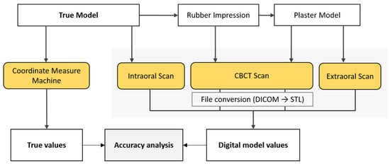
Figure 1.
Schematic overview of study workflow.
2.1. Fabrication of the True Model
An acrylic typodont, maxilla (D51DP-500A; Nissin Dental, Inc., Kyoto, Japan) was used to simulate a patient’s dental arch and prepared to establish the true model (Figure 2).
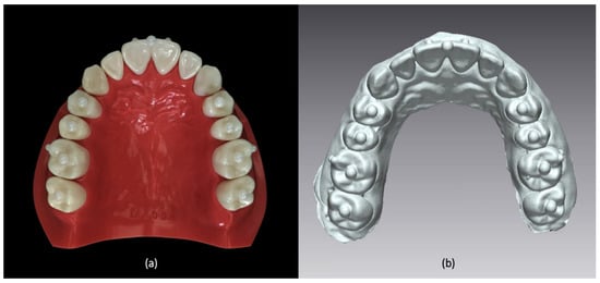
Figure 2.
(a) A true model prepared with acrylic typodont and nine zirconia balls. (b) Digitized model replicated from true model.
As reference points for the distance measurements, nine zirconia balls (Zirconia ball; MS TECH, Gyeonggi-Do, Korea) with a diameter of 3 mm were attached on the center edge of the first incisor and the occlusal surface of the premolars and molars, and eight balls (Zirconia ball; MS TECH, Gyeonggi-Do, Korea) with a diameter of 2 mm were attached on the buccal surface of the first incisors and first molars. Dental resin cement (Multilink N; Ivoclar Vivadent AG, Schaan, Liechtenstein) was used to attach the balls.
2.2. Digitization of the Model
2.2.1. Intraoral Scans
The true model was directly scanned under standard resolution mode with an intraoral scanner (TRIOS 3; 3Shape, Copenhagen, Denmark), and this procedure was repeated 20 times. To ensure stable scanning performance, the operator was trained for a week before the actual scanning procedure. The data digitized with the TRIOS 3 were directly exported in the STL format, and the results were referred to as the intraoral scans.
2.2.2. Impression CBCT Scans
An impression of the true model was made with silicone putty (Aquasil; Dentsply DeTrey GmbH, Germany) and light-body material (Aquasil Ultra XLV; Dentsply Caulk, Milford, MA, USA) by an experienced dental technician following the user’s manual provided by the manufacturer. The impression was then scanned with a RAYSCAN α + CBCT apparatus (Ray Co., Ltd., Hwaseong, Korea) in the object scanning mode (voxel size 100 μm, 14.0 s, 70 kVp, 16 mA). The obtained DICOM data were converted into the STL format via the RayDent converter (i.e., the software provided by the CBCT machine manufacturer). The software was equipped with special algorithms for converting DICOM data from the object scanning mode into a precise digital model. The scanning procedure was repeated 20 times at 3-min intervals, and the resulting 20 digital models were analyzed as the impression CBCT scan models.
2.2.3. Cast CBCT Scans and Cast Extraoral Scans
A plaster model, using type II dental stone (DK Mungyo, Gimhea, Korea), was fabricated by a skilled dental technician from the impression made in the previous step. This procedure was done within 24 h from impression-taking to minimize distortions. The plaster model was scanned with CBCT and an extraoral scanner 20 times at 3-min intervals. For the CBCT scans, the object scanning mode used in the previous impression scan step was applied, and for the extraoral scans, an Identica Hybrid (Medit, Seoul, Korea) with 0.065 mm point space was used. The same software was used to convert the DICOM data from the CBCT-scanned files into STL data. A total of 40 digital models were generated from the CBCT and extraoral optical scans, and they were denoted as the cast CBCT scans and the extraoral scans, respectively.
2.3. Linear Measurements on the X-, Y-, and Z-Axes
Linear measurements were obtained in all directions along the X- (width), Y- (length), and Z-axes (height). Four linear distances on each axis, resulting in a total of 12 measurements, were measured between the centers of the selected reference balls (Figure 3).

Figure 3.
Linear measurements according to X-, Y-, and Z-axes. (a) Linear measurements on X-axis: XPM1, between right and left first premolars; XPM2, between right and left second premolars; XM1, between right and left first molars; and XM2, between right and left second molars. (b) Measurements on Y-axis: YPM1, from the incisor center to the virtual line between right and left first premolars; YPM2, from the incisor center to the virtual line between right and left second premolars; YM1, from the incisor center to the virtual line between right and left first molars; and YM2, from the incisor center to the virtual line between right and left second molars. (c) Measurements on Z-axis: ZMR, between the balls on right first molar; ZIR, between the balls on right incisor; ZIL, between the balls on left incisors; and ZML, between the balls on left first molars. Note that the center of reference ball is marked with cross sign and the measurements are marked with double-headed arrows.
On the X-axis, the distances between the balls on the first premolars (XPM1), second premolars (XPM2), first molars (XM1), and second molars (XM2) were measured. On the Y-axis (length), the straight linear distances from the ball on the incisor edge to the line connecting the balls on the premolars (YPM1, YPM2) and molars (YM1, YM2) were measured. On the Z-axis (height), linear measurements were made between the balls on the occlusal and cervical sides of the right and left incisors (ZIR, ZIL) and the first molars (ZMR, ZML).
The measurement procedures were performed in a way designed to eliminate experimenter-dependent error. For the true model, a CMM (Victor 101208; Dukin Co., Ltd., Daejeon, Seoul) with 0.1 μm resolution and 2.0 + L/300 maximum permissible error per ISO 10360-2 (μm, L:mm) was used, and the resulting values were considered the gold standard values. For the digital models, 3-dimensional analysis software (Geomagic Control X; 3D systems, Braunschweig, Germany) was used to automatically detect the centers of the reference balls and to automatically measure the shortest distance between the centers of the balls (Figure 3). This measurement process was repeatedly done for all 80 digital models obtained via the four different scanning methods (intraoral scans, impression CBCT scans, extraoral scans, and cast CBCT scans).
2.4. Statistical Analysis
For each set of digital model measurements, the mean value was obtained. For each type of digital model obtained from the different scanning methods, four mean values on each axis were compared with the gold standard values. The two-tailed one-sample t-test was used to determine the agreement between them.
The deviation of the mean values on each axis compared to the gold standard was also measured in absolute terms. The deviation was compared among the digital models obtained by different scanning methods on each axis. Analysis of variance was conducted to identify significant differences among the scanning methods using the Turkey post hoc test. The level of significance was set at p < 0.05. IBM SPSS statistics version 23.0 (IBM Corp., Armonk, NY, USA) was used for statistical analysis.
3. Results
Most measurements of the digitized models were statistically significantly different from to the corresponding gold standard measurements, regardless of the scanning method, although the percent deviations of all measurements were less than 4%. Most deviations on the X-axis showed negative values in comparison to the true values, while most deviations on the Z-axis were positive (Table 1).

Table 1.
Linear measurement values and the percent deviation from the true value according to the individual measurements of respective scanning method (units: mm).
The extraoral scan model, followed by the cast CBCT model, showed the least deviation from the gold standard model on the X- and Y-axes, although the deviation of the extraoral scan model was statistically significant. On the Z-axis, the cast CBCT scans showed a significantly greater deviation from the gold standard than the other models. The intraoral scans, impression CBCT scans, and the extraoral scans showed small and comparable deviations on the Z-axis (Table 2).
Table 2.
Mean value of the deviation in each scanning method according to the axis.
The extraoral scan model showed stable measurements, with a small range of the distribution of measured values, whereas the intraoral scans showed a wide range of distribution of the measured values. Both CBCT scan models showed a moderately scattered level of distribution of the measured values (Figure 4).
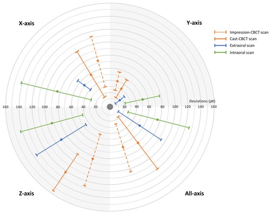
Figure 4.
The accuracy of digitized model is described in a target figure, and the center of the target is determined as the true model value. The digitized model is more accurate when the mean deviation value is close to the target center. The model is also more consistent in linear dimension when the marked range is narrow. Each section of the target represents a different axis. The upper left section represents the X-axis, the upper right represents Y-axis, the lower left represents the Z-axis and lower right represents the total. The mean deviation value is marked with a circle, and the standard deviation is marked as a range.
4. Discussion
In recent years, digitized dental arch models have become a major trend in dentistry. More and more imaging devices enabling digital data acquisition from impressions and plaster models have become available [7]. Accordingly, the accuracy of digital models has been assessed in many previous studies [2,10,14,15,20]. Studies have generally evaluated the accuracy of the digital models obtained by scanning plaster models with various devices or compared linear measurements of digital models with the corresponding values of plaster casts [1,2,3,4]. Those previous studies primarily focused on assessing the accuracy of the scanning devices, whereas we concentrated on analyzing the consequent digital products to see if they were truly accurate compared to the actual patient’s dental arch.
Extraoral optical scanning is currently considered an acceptable method for obtaining a digital model of the full dental arch [6,14,22]. Unfortunately, in this method, a plaster cast of the patient’s dental arch must be made, and the errors that arise from impression-taking and plaster model pouring cannot be disregarded [7,23]. In addition, scanning errors in the hardware and in the postprocessing algorithm increase the overall inaccuracy of the digitized data. Therefore, analyzing the accuracy of digitized models of the full dental arch compared to the patient’s dental arch, rather than a plaster replica, is essential.
Linear measurements were compared across the models in this study as a means of accuracy evaluation. Several previous studies have chosen to analyze measurements of surface precision [1,6,7,8,24]. In our opinion, assessments of surface precision have a high risk of distorted results. Digital model production is susceptible to minor surface flaws, such as bubbles and pearls created during impression-taking or plaster model pouring [25]. The model distortion may increase during scanning if irregularities are present on the surface. The postprocessing of STL data, known as smoothing, also overestimates errors due to surface irregularities.
Kamegawa et al. [21] suggested using CMMs to obtain gold standard values of linear measurements to evaluate the accuracy of digital models. They stated that CMM measurements are highly reliable, although localizing the same landmark on digital models as on the dental cast by CMM is an error-prone process that must be overcome. Rossini et al. [5] also reported that the greatest proportion of errors in linear measurements occurred during the landmark-locating step. In addition, when using a small number of reference points to minimize that source of error, an insufficient number of measurements may be made to detect deviation in three dimensions, due to problems such as torsion or tilting [24]. To overcome these errors, 17 reference balls, which can be automatically detected by any measurement method, were used in the present study. The CMM probe contacted eight points on each ball and automatically found the coordinates of the centers of the reference balls. The measurement software used for the digitized models also automatically recognized the shapes of the balls and detected their centers. Overall, for both the true model and the digital models, manual errors were completely eliminated.
According to Christensen [26], operator technique is closely related to the accuracy of impressions and plaster models. Additionally, even if a skilled dental technologist makes a plaster model according to the manual provided by the manufacturer, errors may occur due to problems during impression-taking, deformation of the material, and the model fabricating environment, such as variation in the mixing ratio, waiting time, and position of the impression body after pouring the plaster [7,26,27]. Since a trained technician in a well-designed laboratory fabricated the plaster model used in this study, the deviation in the size measurements of the digital model produced from the plaster model might be even greater in the normal clinical environment. Further technical innovations should be developed to eliminate conventional dental laboratory procedures as much as possible to reduce errors in digital models.
This study found that none of the methods led to a digital model that was a significantly accurate reproduction of the true dental arch. However, the digital model produced using the extraoral scans showed less deviation than the other digital models produced with an intraoral scanner and CBCT scans. Currently, intraoral optical scanner, the only method to scan a patient’s mouth directly, is recommended for scanning area within a single quarter of the arch to obtain accurate scan data [3,7]. However, in this study the intraoral scanner continuously stitched captured images to scan the full dental arch, and this process might increase the systematic error resulting in the greatest deviation of intraoral scanner model.
Meanwhile, the deviation on the Z-axis was greater than that on the X- and Y-axes in all the digital models. This is consistent with a previous report that showed large deviations in crown length measurements [18]. It can be assumed that the Z-axis expansion of the plaster model was greater than the expansion on the X- and Y-axes, probably because the impression material or rigid tray we used for impression was prevented from expanding on the X- and Y-axes. Moreover, due to the limited vertical height of the tooth crown, smaller reference balls were attached to the Z-axis than to the X- and Y-axes. This possible source of experimental error may explain these results. Additionally, due to relatively low CBCT scanning resolution, along with material-induced causes such as impression distortion or plaster expansion [28,29], errors are accumulated throughout the process of digital model acquisition, resulting in the reduced accuracy of cast CBCT scanning data.
As reported in previous studies, the digital models mostly showed smaller measurement values than the true measurements [14,30]. Researchers have suggested that this tendency of “downsizing” in digital models might be due to the partial volume effect during scanning or algorithms used in the conversion software [30,31,32]. Clinicians should be aware of the possibility of downsized models when using digital models generated using object scanning devices.
Notably, the current study found that the CBCT-generated data were more accurate than the intraoral data, contrary to a previous study [33]. The CBCT scanning protocol conducted in this study includes software that converts image data (DICOM) into digital model data (STL). The software analyzes the impression material and plaster density in the CBCT image data and used a specific algorithm to convert them into more accurate STL data, in order to minimize conversion errors and artifacts. This innovation in the conversion software might have contributed to the enhanced accuracy of the CBCT-produced models.
Impression-scanned models were only produced using CBCT in this study due to inadequacies of the extraoral optical scanner. This unit could not produce a digital surface when scanning the impression material because the light source could not reach the undercut area and therefore did not reflect back to the detector [8]. However, CBCT uses an X-ray beam, which penetrates materials and then reaches the detector, so this scanner functioned well for undercut areas. A further study comparing the accuracy of CBCT and extraoral scanners for dental impressions is needed, as well as the development of a desktop extraoral scanner feasible for impression scans.
In conclusion, digital model accuracy should be assessed based on true dental arch measurements consisting of width, length, and height variables, considering the complex steps involved in digitization. Additionally, the use of a CMM and software-based measurements using reference balls is suggested for minimizing measurement errors. The enhanced accuracy of the CBCT-produced digitized models compared to previous studies suggests the feasibility of further development of CBCT-based models.
Author Contributions
Conceptualization, Y.H.K. and S.-S.H.; Data curation, Y.H.K. and C.-W.W.; methodology, Y.H.K.; formal analysis, Y.H.K., Y.J.C. and C.-W.W.; writing—original draft preparation, Y.H.K. and S.-S.H; visualization, Y.H.K.; supervision, S.-S.H.; funding acquisition, S.-S.H. All authors have read and agreed to the published version of the manuscript.
Funding
The material is based upon work supported the Ministry of Trade, Industry & Energy (MOTIE, Korea) under Advanced Technology Center Program. No.10062362, The development of dental and medical prosthetics modeling, rapid fabrication and integrated trading system based and converged on CBCT image, using Cloud networking.
Conflicts of Interest
The authors declare no conflict of interest.
References
- Kim, S.R.; Kim, C.M.; Jeong, I.D.; Kim, W.C.; Kim, H.Y.; Kim, J.H. Evaluation of accuracy and repeatability using CBCT and a dental scanner by means of 3D software. Int. J. Comput. Dent. 2017, 20, 65–73. [Google Scholar]
- Cho, S.H.; Schaefer, O.; Thompson, G.A.; Guentsch, A. Comparison of accuracy and reproducibility of casts made by digital and conventional methods. J. Prosthet. Dent. 2015, 113, 310–315. [Google Scholar] [CrossRef]
- Guth, J.F.; Runkel, C.; Beuer, F.; Stimmelmayr, M.; Edelhoff, D.; Keul, C. Accuracy of five intraoral scanners compared to indirect digitalization. Clin. Oral Investig. 2017, 21, 1445–1455. [Google Scholar] [CrossRef] [PubMed]
- Camardella, L.T.; Breuning, H.; de Vasconcellos Vilella, O. Accuracy and reproducibility of measurements on plaster models and digital models created using an intraoral scanner. J. Orofac. Orthop. Fortschr. Der Kieferorthopadie Organ/Off. J. Dtsch. Ges. Fur Kieferorthopadie 2017, 78, 211–220. [Google Scholar] [CrossRef] [PubMed]
- Rossini, G.; Parrini, S.; Castroflorio, T.; Deregibus, A.; Debernardi, C.L. Diagnostic accuracy and measurement sensitivity of digital models for orthodontic purposes: A systematic review. Am. J. Orthod. Dentofac. Orthop. Off. Publ. Am. Assoc. Orthod. Its Const. Soc. Am. Board Orthod. 2016, 149, 161–170. [Google Scholar] [CrossRef] [PubMed]
- De Gonzalez Villaumbrosia, P.; Martinez-Rus, F.; Garcia-Orejas, A.; Salido, M.P.; Pradies, G. In vitro comparison of the accuracy (trueness and precision) of six extraoral dental scanners with different scanning technologies. J. Prosthet. Dent. 2016, 116, 543–550. [Google Scholar] [CrossRef] [PubMed]
- Su, T.S.; Sun, J. Comparison of repeatability between intraoral digital scanner and extraoral digital scanner: An in-vitro study. J. Prosthodont. Res. 2015, 59, 236–242. [Google Scholar] [CrossRef] [PubMed]
- Flugge, T.V.; Schlager, S.; Nelson, K.; Nahles, S.; Metzger, M.C. Precision of intraoral digital dental impressions with iTero and extraoral digitization with the iTero and a model scanner. Am. J. Orthod. Dentofac. Orthop. Off. Publ. Am. Assoc. Orthod. Its Const. Soc. Am. Board Orthod. 2013, 144, 471–478. [Google Scholar] [CrossRef]
- Winkler, J.; Gkantidis, N. Trueness and precision of intraoral scanners in the maxillary dental arch: An in vivo analysis. Sci. Rep. 2020, 10, 1172. [Google Scholar] [CrossRef]
- Lightheart, K.G.; English, J.D.; Kau, C.H.; Akyalcin, S.; Bussa, H.I., Jr.; McGrory, K.R.; McGrory, K.J. Surface analysis of study models generated from OrthoCAD and cone-beam computed tomography imaging. Am. J. Orthod. Dentofac. Orthop. Off. Publ. Am. Assoc. Orthod. Its Const. Soc. Am. Board Orthod. 2012, 141, 686–693. [Google Scholar] [CrossRef]
- Kau, C.H.; Littlefield, J.; Rainy, N.; Nguyen, J.T.; Creed, B. Evaluation of CBCT digital models and traditional models using the Little’s Index. Angle Orthod. 2010, 80, 435–439. [Google Scholar] [CrossRef] [PubMed]
- Rangel, F.A.; Maal, T.J.J.; de Koning, M.J.J.; Bronkhorst, E.M.; Berge, S.J.; Kuijpers-Jagtman, A.M. Integration of digital dental casts in cone beam computed tomography scans-a clinical validation study. Clin. Oral Investig. 2017. [Google Scholar] [CrossRef] [PubMed]
- Lee, S.M.; Hou, Y.; Cho, J.H.; Hwang, H.S. Dimensional accuracy of digital dental models from cone-beam computed tomography scans of alginate impressions according to time elapsed after the impressions. Am. J. Orthod. Dentofac. Orthop. Off. Publ. Am. Assoc. Orthod. Its Const. Soc. Am. Board Orthod. 2016, 149, 287–294. [Google Scholar] [CrossRef] [PubMed]
- Wesemann, C.; Muallah, J.; Mah, J.; Bumann, A. Accuracy and efficiency of full-arch digitalization and 3D printing: A comparison between desktop model scanners, an intraoral scanner, a CBCT model scan, and stereolithographic 3D printing. Quintessence Int. (Berl. Ger. 1985) 2017, 48, 41–50. [Google Scholar] [CrossRef]
- Jiang, T.; Lee, S.M.; Hou, Y.; Chang, X.; Hwang, H.S. Evaluation of digital dental models obtained from dental cone-beam computed tomography scan of alginate impressions. Korean J. Orthod. 2016, 46, 129–136. [Google Scholar] [CrossRef] [PubMed][Green Version]
- Hwang, J.J.; Jung, Y.H.; Cho, B.H. The need for DICOM encapsulation of 3D scanning STL data. Imaging Sci. Dent. 2018, 48, 301–302. [Google Scholar] [CrossRef]
- De Waard, O.; Rangel, F.A.; Fudalej, P.S.; Bronkhorst, E.M.; Kuijpers-Jagtman, A.M.; Breuning, K.H. Reproducibility and accuracy of linear measurements on dental models derived from cone-beam computed tomography compared with digital dental casts. Am. J. Orthod. Dentofac. Orthop. Off. Publ. Am. Assoc. Orthod. Its Const. Soc. Am. Board Orthod. 2014, 146, 328–336. [Google Scholar] [CrossRef]
- Kim, J.H.; Kim, K.B.; Kim, W.C.; Kim, J.H.; Kim, H.Y. Accuracy and precision of polyurethane dental arch models fabricated using a three-dimensional subtractive rapid prototyping method with an intraoral scanning technique. Korean J. Orthod. 2014, 44, 69–76. [Google Scholar] [CrossRef]
- Keating, A.P.; Knox, J.; Bibb, R.; Zhurov, A.I. A comparison of plaster, digital and reconstructed study model accuracy. J. Orthod. 2008, 35, 191–201. [Google Scholar] [CrossRef]
- Wiranto, M.G.; Engelbrecht, W.P.; Tutein Nolthenius, H.E.; van der Meer, W.J.; Ren, Y. Validity, reliability, and reproducibility of linear measurements on digital models obtained from intraoral and cone-beam computed tomography scans of alginate impressions. Am. J. Orthod. Dentofac. Orthop. Off. Publ. Am. Assoc. Orthod. Its Const. Soc. Am. Board Orthod. 2013, 143, 140–147. [Google Scholar] [CrossRef]
- Kamegawa, M.; Nakamura, M.; Fukui, Y.; Tsutsumi, S.; Hojo, M. Direct 3-D morphological measurements of silicone rubber impression using micro-focus X-ray CT. Dent. Mater. J. 2010, 29, 68–74. [Google Scholar] [CrossRef] [PubMed]
- Kumar, A.A.; Phillip, A.; Kumar, S.; Rawat, A.; Priya, S.; Kumaran, V. Digital model as an alternative to plaster model in assessment of space analysis. J. Pharm. Bioallied Sci. 2015, 7, S465–S469. [Google Scholar] [CrossRef] [PubMed]
- Christensen, G.J. Will digital impressions eliminate the current problems with conventional impressions? J. Am. Dent. Assoc. (1939) 2008, 139, 761–763. [Google Scholar] [CrossRef]
- Ender, A.; Mehl, A. Full arch scans: Conventional versus digital impressions—An in-vitro study. Int. J. Comput. Dent. 2011, 14, 11–21. [Google Scholar] [PubMed]
- Rudolph, H.; Salmen, H.; Moldan, M.; Kuhn, K.; Sichwardt, V.; Wostmann, B.; Luthardt, R.G. Accuracy of intraoral and extraoral digital data acquisition for dental restorations. J. Appl. Oral Sci. Rev. Fob 2016, 24, 85–94. [Google Scholar] [CrossRef] [PubMed]
- Christensen, G.J. The state of fixed prosthodontic impressions: Room for improvement. J. Am. Dent. Assoc. (1939) 2005, 136, 343–346. [Google Scholar] [CrossRef] [PubMed]
- Lacy, A.M.; Fukui, H.; Bellman, T.; Jendresen, M.D. Time-dependent accuracy of elastomer impression materials. Part II: Polyether, polysulfides, and polyvinylsiloxane. J. Prosthet. Dent. 1981, 45, 329–333. [Google Scholar] [CrossRef]
- Kihara, H.; Hatakeyama, W.; Komine, F.; Takafuji, K.; Takahashi, T.; Yokota, J.; Oriso, K.; Kondo, H. Accuracy and practicality of intraoral scanner in dentistry: A literature review. J. Prosthodont. Res. 2019. [Google Scholar] [CrossRef]
- Michalakis, K.X.; Stratos, A.; Hirayama, H.; Pissiotis, A.L.; Touloumi, F. Delayed setting and hygroscopic linear expansion of three gypsum products used for cast articulation. J. Prosthet. Dent. 2009, 102, 313–318. [Google Scholar] [CrossRef]
- Abizadeh, N.; Moles, D.R.; O’Neill, J.; Noar, J.H. Digital versus plaster study models: How accurate and reproducible are they? J. Orthod. 2012, 39, 151–159. [Google Scholar] [CrossRef]
- Maroua, A.L.; Ajaj, M.; Hajeer, M.Y. The Accuracy and Reproducibility of Linear Measurements Made on CBCT-derived Digital Models. J. Contemp. Dent. Pract. 2016, 17, 294–299. [Google Scholar] [PubMed]
- Lascala, C.A.; Panella, J.; Marques, M.M. Analysis of the accuracy of linear measurements obtained by cone beam computed tomography (CBCT-NewTom). Dentomaxillofac. Radiol. 2004, 33, 291–294. [Google Scholar] [CrossRef] [PubMed]
- Nowak, R.; Wesemann, C.; Robben, J.; Muallah, J.; Bumann, A. An in-vitro study comparing the accuracy of full-arch casts digitized with desktop scanners. Quintessence Int. 2017, 20, 667–676. [Google Scholar]


© 2020 by the authors. Licensee MDPI, Basel, Switzerland. This article is an open access article distributed under the terms and conditions of the Creative Commons Attribution (CC BY) license (http://creativecommons.org/licenses/by/4.0/).